Einleitung

Benutze diese Anleitung, um die rechte Tastenplatine in deinem Steam Deck auszutauschen.

Achte während der Reparatur auf allgemeine Vorsichtsmaßnahmen zur Vermeidung von elektrostatischen Entladungen (ESD = engl. electrostatic discharge).

In diesen Schritten wird nur beschrieben, wie die du die Tastenplatine deiner Spielkonsole physisch ausbauen und ersetzen kannst. Möglicherweise benötigst du zusätzliche Software-Tools und Kalibrierungsverfahren, damit die Ersatzplatine wie vorgesehen funktioniert.

  1. vQyR3PAE4HOMSLAZ
    vQyR3PAE4HOMSLAZ
    aIKAs5r3P3bY2iTE
    hD1USYJCkAbkluud
    • Schalte das Steam Deck ein und entlade den Akku auf unter 25%, bevor du mit der Reparatur beginnst. Aus einem geladenen Lithium-Ionen-Polymer-Akku können gefährliche Chemikalien austreten, wenn er versehentlich angestochen wird.

    • Valve empfiehlt als zusätzliche Sicherheitsmaßnahme den Akku im BIOS in den battery storage mode (Akkuspeichermodus) zu versetzen, bevor du mit Reparaturen an inneren Bauteilen anfängst. Hier steht, wie das geht.

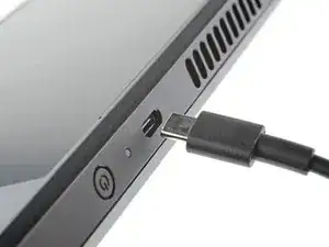
    • Schalte das Steam Deck komplett aus und ziehe alle Stecker ab.

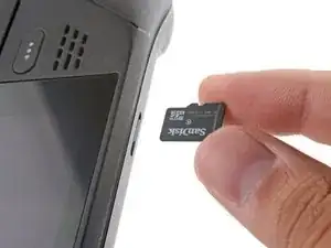
    • Wenn du eine microSD-Karte angeschlossen hast, dann musst du sie entfernen, bevor du das Steam Deck öffnest. Wenn du die Rückseite ausbaust, ohne die Karte zu entfernen, kann sie in zwei Teile zerbrechen.

    • Es kann hilfreich sein, wenn du während der Reparatur das Steam Deck mit der Oberseite nach unten in seine Hülle legst, um die Joysticks zu schützen und Wackeln zu vermeiden.

  2. bpUGGPG32OkLXnC4

    there should be a picture of the SD card slot at the start of every Steam Deck teardown. i know the note is there but i generally use the pictures to guide me and forgetting to remove the SD card is a very critical step

    Nathan Barrow -

    I agree, I just broke mine...

    Camille B -

    What is the the #1 philips used for? Only the #0 is mentioned in the instructions.

    Christopher Martin -

    I wish they would specify which size to use for which screws.

    Mark D -

    I found it easiest to use a PH1 for the red screws, and PH0 for the rest (including the internals.)

    Chris Clawson -

    Be careful you can strip the screws take your time

    I use PH00 bit

    jaybush74 -

    I used the PH1 bit for this. You can use smaller bits but ideally there should be no play of the bit in the screw head.

    Charles Semple -

    are there playstation replacements (circle,square,cross,triangle)

    Deór -

    I used the ifixit tools and used the 00 size for the screws on the back.

    Luis B -

    I've completed the guide and found it very helpful!

    I think somewhere in this part it would be helpful to name the size of the correct Phillips driver to use:

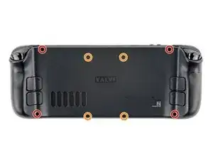
    Use a Phillips driver to remove the eight screws securing the back cover:

    Four 9.5 mm screws

    Four 5.8 mm screws

    Maynard -

    I used the PH1 for the 9.5mm screws and PH00 for the 5.8mm screws. The PH0 wanted to strip one of the small ones.

    Pol Llovet -

  3. 6jtVcFtMGa5ZMqcF
    6jtVcFtMGa5ZMqcF
    Ux5LEj3JfJlkmQMQ
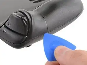
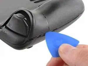
    • Setze ein Plektrum in die schmale Fuge zwischen Rückabdeckung und Vorderschale an der Kante des rechten Griffs ein.

    • Heble die Rückabdeckung hoch, um sie aus den Clips zu lösen, mit denen sie befestigt ist.

    I found it easiest to start this process at the top of the device near the fan exit.

    Peter Lindberg -

    second that and inserting the pick in the bottom middle and sliding the pick to each side

    Sub -

    I also found the top near the fan exit to be easier

    Travis Patton -

    Thank you for this tip, it definitely was easy starting at the top instead of by the bumper/triggers. After I opened the top I did the bottom and then it was way easier to gently open the sides. be very careful and go slowly to make sure that none of the clips are damaged

    Luis B -

    this as suggested above:

    1. open the top

    2. open the bottom

    3.gently open the sides

    austrasier -

    same; i pried from the top of the screen area. I was unable to find an opening on the side

    Dennis Wu -

    I also started from the middle of the deck and worked my way out since I couldn't get a grip with the pick on the deck's side grips. Since this is a common step for pretty much all guides for opening the deck I think it's also worth noting that you should be careful not to bend the trims/seams where the front and back covers meet with the pick. When I first opened my deck you can definitely see where I nudged the pick in between the covers since I was probably using too much force on the pick itself.

    Kaleb McKone -

    It would be useful to note here that if you want to insert the little blue triangular iFixit opening picks into the right side along the edge, there isn't actually a gap as the directions say, at least not on newer Decks. You'll be making the initial gap using the pick. Brace it on something because you will need to use enough downward force that you're flexing the pick a bit and it'll probably be digging into the skin of a bare hand. With enough force suddenly it will make a click and go in just a bit, and then you're in business.

    CaptFrost -

    plastic picks didnt work for me but finger males did the job on prying this open

    jacobbagsic -

    I found it easiest to open starting with R1 or L1 buttons and proceeding to the center of the top edge

    Karol Gro -

  4. 6IvIWWqEXPTqW1XB
    6IvIWWqEXPTqW1XB
    1FxwYDjIGOAOCZT2
    KpIx4YIAZrDH1b5T
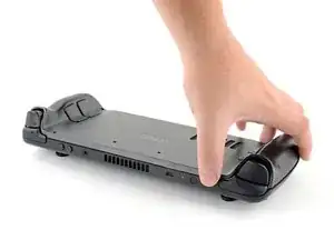
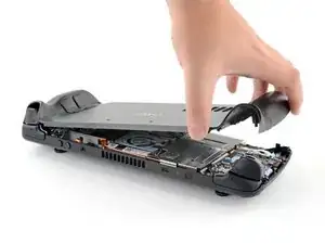
    • Wenn alle Clips von einer Kante gelöst sind, kann der Rest ganz einfach entfernt werden.

    • Fasse die Rückabdeckung an der Öffnung, die du gerade erstellt hast, und ziehe sie nach oben vom Gerät weg, um die Clips an den langen Kanten zu lösen.

    • Entferne die Rückabdeckung.

    If you have an SD card, you will want to take it out. I followed the guide and didn't think about the SD card I had inside. When I went to snap the case back on it clapped shut on the exposed SD card, shearing it in half and leaving the bottom half stuck in the SD card slot. I am still endeavoring to get it out.

    Novice -

  5. WuMbLgtJF5JwQtjF
    WuMbLgtJF5JwQtjF
    I6pEKNGEKEDbNymT
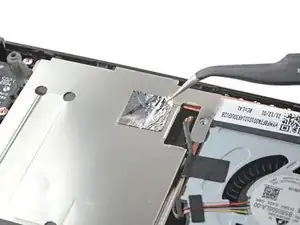
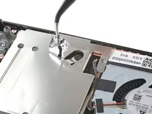
    • Entferne mithilfe einer Pinzette das Stück Klebefolie auf der versteckten Schraube auf der Platinenabschirmung.

    • Versuche die Klebefolie nach Möglichkeit nicht zu zerreißen, sodass sie wiederverwendet werden kann. Wenn es nötig ist, kannst du dir auch ein passendes Ersatzstück aus Aluminiumfolie zurechtschneiden und einkleben.

    Use some heat here from a hairdryer to make this part easier.

    If you screw up here you can replace the little aluminium square with some aluminium tape from Amazon. No less than 50 microns thick, slightly thicker is fine. and the square is 13mm both ways.

    Matt S -

  6. fpjCmGxopRvFvGbm
    • Benutze einen Schraubendreher, um die drei Kreuzschlitzschrauben zu entfernen, mit denen die Abschirmung der Platine befestigt ist:

    • Eine 3,4 mm Schraube

    • Zwei 3,7 mm Schrauben

    The procedure ended here for me, used an ifixit PH 00 bit on the screw behind the aluminium tape, bit wouldnt bite too great, one wrong twist and the screw was stripped. Not sure who or what initially screwed in that particular screw as the rest of the screws on the shield were fine, but boy is it in there tight. So now i have a stripped screw and a botched ssd replacement, don't think valve will let me RMA for this, but i'll give it a try and update accordingly.

    Y. van S -

    Any updates? Did they let you RMA?

    Emanuel Gjoni -

    I found one screw to be ridiculously tight too, managed to undo it without stripping thanks to reading your comment beforehand and going extra careful. Not going to lie, it was a tense moment :D

    Andy HL -

    I think the tendency is to go too small on the screwdriver bits because you're working on small electronics.

    I used the PH1 bit on the screw under the foil and the PH0 bit for the two remaining screws without any problems.

    Charles Semple -

    What does this shield actually do? Some kind of magnetic protection?

    Corey Cleric -

    if I had to replace the key (R2) and that's it, can I directly remove it or do I have to act here on the motherboard too?

    pujattidanny -

    have you gotten an answer yet? trying to change mines as well but dont wanna do too much to the deck

    briaNN -

    button Not key, i’m sorry

    pujattidanny -

    I used the ifixit tools and used the 00 PH for these screws with no issue

    Luis B -

    If only swapping the SSD, it is not necessary to remove the top left 3.7mm screw. The heat shield is flexible enough that you can move it out of the way to access the SSD screw. For me this was necessary as the 3.7mm screw was completely unmovable and quickly stripped.

    Scott A -

    FYI there is a little pin on the cover that slots into the board. It is located near the top screw. I needed that to be inserted for the cover to go back down properly.

    Seth Robinson -

  7. JXePTdtVUbrOvVJT
    JXePTdtVUbrOvVJT
    QqjInaZugM3yJK1q

    When putting back on, run a pick along the edge of the shield between the wires to make sure nothing is pinching and the wires are clear of the shield before screwing down.

    Matt S -

  8. XjI1homB4a5VNhbV
    XjI1homB4a5VNhbV
    qvcjxPUTxawsUUMB
    qa3R33nVHlO1SOpy
    • Fasse das Akkukabel an seiner Zuglasche und ziehe es vom Motherboard weg, um es abzutrennen.

    • Du kannst den Stecker auch mit dem flachen Ende des Spudgers aus seinem Anschluss herausschieben und dann endgültig mit der Hand abtrennen.

    After fully reassembling my device I found that my battery was not showing any stats anymore. I couldn't start the device without being plugged in, however if I restarted it would stay on even if my power cable was detached. Battery showed 0%. It turns out I had not fully reinserted the battery cable at this stage during reassembly. MAKE SURE YOU PUSH IT ALL THE WAY BACK IN!

    Michael Hoffmann -

    Awesome thanks for this tip!

    petergeranio -

    It is helpful to lift up gently with a the tapered end of a spudger underneath the tucked-in portion of the battery cable, creating a bit of flex in the cable before pulling on the pull tab. I found that without doing so, the fabric pull-tab simply tore off of the cable under light-to-moderate force (the fabric itself ripped cleanly across, like a paper towel). Careful, gentle pressure with a spudger can be used to remove the plug by prying gently on the rear ridge of the plastic plug (not the wire!) if this happens.

    Gene Eckser -

    This is exactly what happened to me. Maybe it was a pull tab previously, mine was a ribbon cable that tore - captured the image here: https://www.ianwootten.co.uk/2022/11/22/...

    Ian Wootten -

    I found it less scary and easier to remove the battery connection by using a fingernail on the ridge and pushing it off the connector. I felt like pulling on the battery cable was too harsh.

    montgomery mchargue -

    Upon plugging the battery back in, I found it easy to use two spudgers- one on each side- to pull/push the connector back into it's port. Be careful to not put any pressure on the battery wires themselves.

    montgomery mchargue -

    When reconnecting the battery cable, you'll know when it's inserted and power is restored, because the white LED will illuminate at the top of the Deck near the power button. You should be able to see it while you're reconnecting the battery cable

    Michael Davis -

    Why not just let the battery discharge completely and then not have to disconnect it?

    Jeffrey Martin -

    Completely discharging a battery reduces its lifespan. It's completely unnecessary.

    Stefan Camporese (CENTER) -

    Because no lipo battery is ever completely discharged -- you would not be able to recharge it if it was. There will always be enough power left in it to cause damage if shorted even if it isn't charged enough to power up the device it's connected to.

    David Cameron -

    I would personally not recommend pulling the tab. It doesn’t apply force at the correct angle. You should revise these instructions to advise using a combination of pulling on the tab, and careful pressure on the connector towards the right of the mainboard to carefully work it out.

    Using the pull tab alone could cause problems if not done extremely carefully.

    William Winborne -

    This part was wayyyyy easier than I anticipated and I worried for nothing because I used the ifixit spudger to push it out a bit and then I literally used my finger nail and was able to slide it right off. Dont be afraid, its not that difficult and its not that delicate to break if you do it patiently

    Luis B -

    I inserted the cable very firmly with a spunger, being careful not to press down too hard on the cables, and even tried redoing it, but I don't see any LED illumination. I am now unable to boot the deck into the boot manager. Any additional tips?

    junefish -

  9. Z6LWlYlyiV1d41Sj
    Z6LWlYlyiV1d41Sj
    Bd5yElJmIQmYJhWA
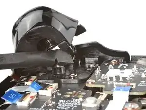
    • Der rechte Trigger wird sich zu deiner Linken befinden, wenn du am Steam Deck arbeitest, da es verkehrt herum liegt.

    • Die Trigger des Steam Deck sind mit zwei Stiften an der Trigger-Halterung befestigt, die gleichzeitig als Scharnier dient.

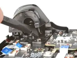
    • Setze das flache Ende eines Spudgers auf die Innenkante des rechten Clips des Triggers.

    • Klappe den Trigger-Clip heraus, und aus dem Stift nach oben heraus, um ihn zu lösen.

    • Achte beim Zusammenbau darauf, dass du mit dem Einsetzen zuerst beim ganz außen liegenden Stift anfängst. Sobald er sitzt, kannst du den Trigger herunterdrücken, sodass er im ganz innen liegenden Stift einrastet, dabei solltest du ein "Klick"-Geräusch hören.

    • Stelle sicher, dass die Trigger-Feder richtig ausgerichtet ist. Teste die Trigger-Funktion, bevor du mit dem Zusammenbau weitermachst.

  10. VTKgnmBtvgYJvUWC
    VTKgnmBtvgYJvUWC
    yyY4vAbCLHDPMtco
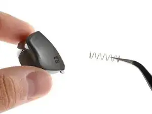
    • Entferne den rechten Trigger.

    • Achte darauf, die Trigger-Feder nicht zu verlieren. Sie wird auf einen Stift auf der Unterseite des Triggers aufgedrückt.

  11. LQINddXT3HZYFWPl
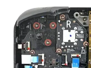
    • Benutze einen Kreuzschlitzschraubendreher, um die drei 5,2 mm Schrauben zu entfernen, mit denen die rechte Trigger-Halterung befestigt ist.

  12. mKjQBX3Vit1OxlLK
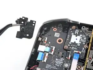
    • Entferne die rechte Trigger-Halterung.

    • Ersatztrigger müssen kalibriert werden, damit sie funktionieren, wie sie sollen. Folge dieser Anleitung, um deinen Trigger zu kalibrieren.

    The right bumper button on my switch deck stopped working after the deck was accidentally dropped from 5ft. When I got to this step of the instructions, I was able to see that the momentary switch that the button triggers had been bent backwards from the impact, making it difficult for the button to trigger the switch. I bent the switch back to its original position, which fixed the mechanical problem. Unfortunately the solder joints for the switch cracked when I pressed the switch forward. I re-flowed the solder joints with a tiny Weber iron that I filed down to a narrow point. The button works properly now.

    Paul Krakow -

  13. AtrScWB5Z5IjKkYn
    AtrScWB5Z5IjKkYn
    GqM1ccewmHIdOPZV
    NGcIXBIZxxHprmlt
    • Benutze das spitze Ende eines Spudgers, um den kleinen Sicherungsbügel am ZIF-Verbinder des Analogstick-Kabels anzuheben.

    • Schiebe das Kabel mithilfe einer Pinzette aus seinem Anschluss.

    • Fasse das Kabel an der blauen Zuglasche und nicht am Kabel selbst.

  14. Xu4iXTvqG21o6Dig
    Xu4iXTvqG21o6Dig
    THZNBkLcn5NEWFMN
    • Benutze einen Kreuzschlitzschraubendreher, um die drei 5,2 mm Schrauben zu entfernen, mit denen der Analogstick befestigt ist.

    • Beim Zusammenbau musst du das Steam Deck möglicherweise anheben, sodass es nicht auf dem neuen Analogstick aufliegt, während du die Schrauben festziehst.

  15. UCIWJnia2kpFaXIQ
    UCIWJnia2kpFaXIQ
    kBE2sNfXuLOlE4Lb
    • Entferne den rechten Analogstick.

  16. W2p5olTWVO3ceYnJ
    W2p5olTWVO3ceYnJ
    DE2NYH3sCrCUYlne
    5IBXZW42jyc3UOOQ
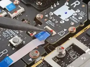
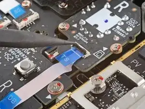
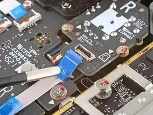
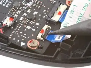
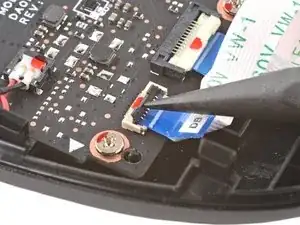
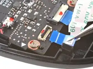
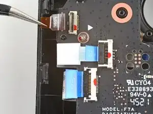
    • Verwende das spitze Ende eines Spudgers, um den kleine Sicherungsbügel am ZIF-Verbinder des Tastenplatinen-Kabels anzuheben.

    • Schiebe das Kabel mit einer Pinzette aus seinem Anschluss.

    • Fasse das Kabel an der blauen Zuglasche, und nicht am Kabel selbst.

  17. SLGtACaPInADUamk
    SLGtACaPInADUamk
    aHbhNls2exSLcgpJ
    sFKLQMvIETKlp2SY
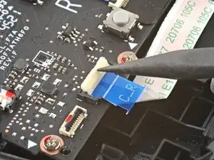
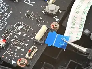
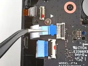
    • Benutze das spitze Ende eines Spudgers, um den kleinen Sicherungsbügel am ZIF-Verbinder des Tastenplatinen-Verbindungskabels hochzuheben.

    • Schiebe das Kabel mit einer Pinzette aus seinem Anschluss.

    • Fasse das Kabel an der blauen Zuglasche, und nicht am Kabel selbst.

    Be very mindful of this cable during re-assembly, if this cable isn't fully seated properly the deck will turn on slowly and not be able to recognize any inputs besides the touch screen.

    Peter Lindberg -

  18. rTrrqnjQ1YgUL1h2
    rTrrqnjQ1YgUL1h2
    xpbXoTMhEKMP5QMA
    RF2BdkmLeFpNv16W
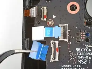
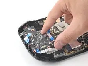
    • Benutze das spitze Ende eines Spudgers, um die kleinen Sicherungsbügel an den restlichen ZIF-Verbindern der Tastenplatine hochzuheben. Schiebe die Kabel mit einer Pinzette aus ihren Anschlüssen:

    • Trenne das Kabel der Aktionstasten ab.

    • Trenne das Kabel der Touchpad-Platine ab.

    • Trenne das Touchpad-Kabel ab.

    Be especially careful disconnecting and reconnecting the touchpad cable. It is short and can pull out on the touchpad side fairly easily. Reconnecting it requires splitting open the touchpad itself which is difficult to do without damaging the springs.

    acey_zero -

  19. xQLjPFh5hwHFBmRY
    xQLjPFh5hwHFBmRY
    RjjMX1rLPLKhGEpL
    uSZgIBXoP6O52KVh
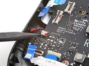
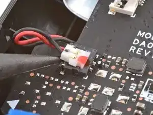
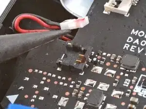
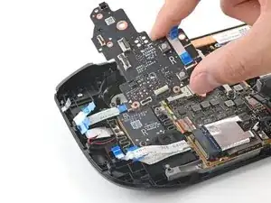
    • Benutze die Spitze eines Spudgers, um das Kabel der Haptik anzuheben und abzutrennen.

    Personally, i think this should just be a suggested step, since the connector is different and requires more force to disconnect than the ribbon cable connectors and you can leave this connected and lay the board over to the side without disconnecting this and still access the buttons.

    Peter Lindberg -

    I agree with Peter on this. I tried fixing my right bumper before ordering a replacement and during disassembly I followed these instructions exactly and still broke the bracket that holds the haptics connector. Luckily my haptics seem to still be working after putting it back together but I have a feeling it will disconnect on its own after some time and I will be needing a whole new button board.

    Biscuits -

    I did this very carefully and the bracket still broke

    Christian McCarthy -

    I broke the down part of the bracket as well. Glued it back on with some crazy glue applied with a wooden toothpick (to make sure to not touch anything else). Haptics still working. Next time I don't think I'll remove that connector.

    Sébastien M -

  20. U12iBFfLK5ZeiUlZ
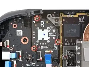
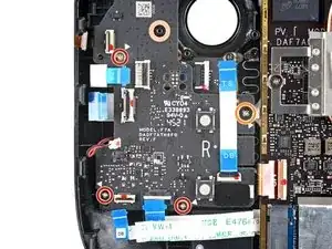
    • Benutze einen Kreuzschlitzschraubendreher, um die vier Schrauben zu entfernen, mit denen die rechte Tastenplatine befestigt ist:

    • Drei 5,2 mm Schrauben

    • Eine 3,9 mm Schraube

  21. CEAr6IVGoPwqDjKe
    CEAr6IVGoPwqDjKe
    1ZV3y1HENT2f4STc
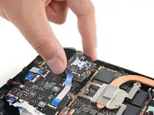
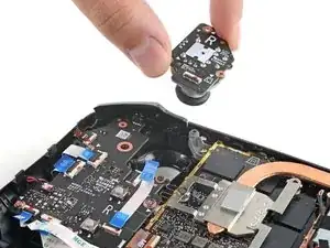
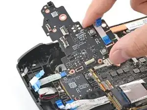
    • Entferne die rechte Tastenplatine.

    • Achte auf die Quick-Access-Taste und ihre Membran, den sobald die rechte Tastenplatine ausgebaut ist, halten sie nicht mehr.

Abschluss

Um dein Gerät wieder zusammenzubauen, folge den Schritten dieser Anleitung in umgekehrter Reihenfolge.

Entsorge deinen Elektromüll fachgerecht.

Lief die Reparatur nicht wie geplant? Versuche es mit einigen grundsätzlichen Lösungsansätzen, ansonsten findest du in unserem Steam Deck Forum Hilfe bei der Fehlersuche.

Carsten Frauenheim

Mitglied seit: 10/03/20

88317 Reputation

17 Kommentare

When will this part be available?

Eric Canals -

Is there any update to when this part will be available?

Tim Ceesay -

Will this part not be available due to their need being a special calibration or hardware step? Having past six months this makes one think the part is not possible with end user due to another factor.

zZz -
Is there any estimated time to when this part will become available?

David Chan -
Parroting everyone else. When will this part be available?

Mario Noriega -
Yes, I need this part, as well. The plastic bumper piece is fine... the button on the board itself is my issue with my R1 button. Need this part... but don't want to send my Steam Deck away for several weeks on warranty... would rather fix it myself.

Dan Lnenicka -

I fixed the micro switch myself, see my comment: Steam Deck rechte Tastenplatine tauschen

Shane Qi -

I finally broke my screen (kid stepped on it next to my bed!) and I was going to buy both this part and a screen from iFixit and do the repairs myself.

This part isn't available! I guess I'll try and send it on warranty.

Andrew Ballinger -

Hello I want to buy this part please

Blake N. -

Same here daughter dropped my deck and right button ripped from the board would really like to replace the board ASAP

Tom Just -

I fixed the micro switch myself, see my comment hope it helps: Steam Deck rechte Tastenplatine tauschen

Shane Qi -

When is this part going to be available to purchase? It's ridiculous that people have been asking the same question for months without any response at all

Jake Guest -

Installing these boards in the Steam Deck requires special calibration that isn't currently publicly available. As of right now we don't know if/when these could be available for purchase.

Carsten Frauenheim -

If you are here because the L1/R1 micro switch is broken, you can replace just the micro switch. I've done it recently:

1. the micro switch I used was the sync/pair button of the Xbox controller, and it works just fine (iFixit sells the Xbox controller motherboard for $15 each)

2. later, I found the micro switch's model number: "TL3340AF160QG" (<$1 each)

3. I used a soldering iron to install it. It's not easy, but DIY-able. I have very little soldering experience, and I fixed it myself.

4. If you use hot air, don't blow directly on the plastic part of the micro switch because it could easily melt.

Here is the thread where I documented this project: https://mastodon.social/@shaneqi/1100088...

Shane Qi -

This only works if the solder pads don't rip off. I think a lot of us have broken pads and need alternate points of contact

Christian McCarthy -

@christianm74231 good point. In that case, we'd still need to wait for the board to be available, or RMA the deck.

Shane Qi -

I don’t suggest others do this, but this is what I did to “fix” my 512 GB deck:

All I had to do was buy a brand new 64 GB Steam Deck and I swapped DBs … The only problem (besides the fact that I had just paid $400 for a new Steam Deck when I only needed the DB) was that the L and R DB were connected by a different number of ribbon cables. My 512 GB Deck had one ribbon cable connecting the L and R DB together whereas the 64 GB Deck had two smaller ribbon cables, so I couldn’t just swap out the one side. Once I swapped both DBs and cables and put it all together, the shoulder buttons worked, but the trackpads could no longer detect pressure, so I couldn’t “click” with them. It wasn’t a huge loss though because I could still use Steam+LT/RT to perform mouse clicks.

Christian McCarthy -