Einleitung

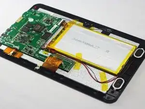
In this guide you will remove the back cover of the device and disconnect the motherboard from the surrounding components. You will then unscrew the motherboard from the device and replace it if need be.

Because this task requires the use of a soldering iron, prior experience with soldering/desoldering will be beneficial.

  1. maUWjIAdwvsjZ6By
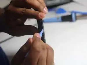
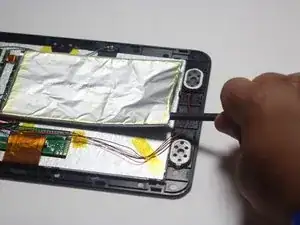
    • Wedge the plastic opening tool between the back cover of the device and the front panel.

    • You will hear a snapping sound as the cover is separated from the body of the device.

  2. lhFeLCWfEiSxICV5
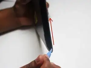
    • Slide the opening tool along the seam between the front panel and the back cover to un-clip the remaining connections around the device.

    • Again, you will hear a snapping sound as the cover is separated from the body of the device.

  3. QIUocuIlYthYw62V
    QIUocuIlYthYw62V
    ixu1Drea45QeXCHY
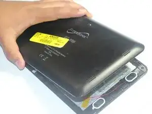
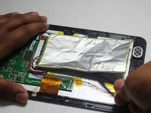
    • Lift the back cover from the body of the device to expose the internal components.

  4. aSXDHCcq62dn4UXh
    aSXDHCcq62dn4UXh
    etLeXG1ErMexMI34
    tkNTrxikGwVAYS4G
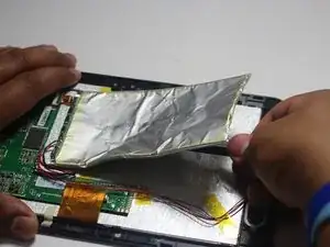
    • Remove the Battery

    • The battery is secured to the back panel with tape and glue.

    • Peel back the tape around the battery and discard it.

    • Tear through the adhesive holding the battery by using the spudger tool.

  5. KOUQcvCWK3OX4IHk
    KOUQcvCWK3OX4IHk
    XdnIuaLVKTS6sNVC
    DUq31GHaRE3YI6nZ
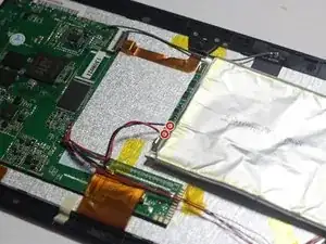
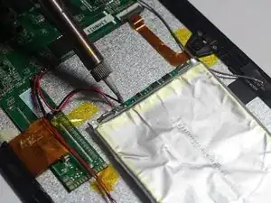
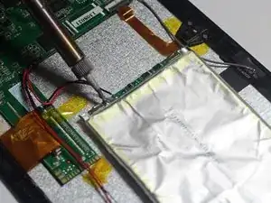
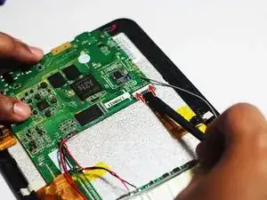
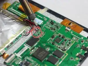
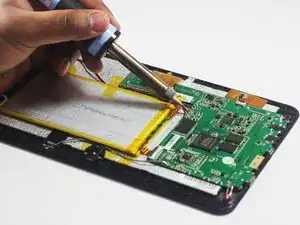
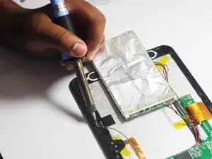
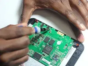
    • Desolder the 2 Battery Wires

    • The Battery has two wires connected to the motherboard (one black and one red).

    • If you're unfamiliar with soldering or desoldering check out this guide.

    • Be sure to wear protective eye wear. The soldering iron will become extremely hot and a potential danger, so make sure you are aware of your surroundings.

    After i replaces the battery it still doesn't work

    daledelorise -

  6. EZe1ltlOoIebAdyD
    EZe1ltlOoIebAdyD
    ZHWBJAJNdv5hvPpK
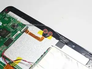
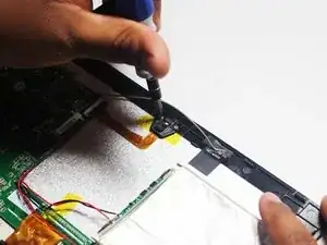
    • Remove the two Phillips #00 screws attaching the housing of the camera to the device.

  7. DHkJAQZiKstWSYlm
    • With the screws removed you should easily be able to remove the camera unit.

  8. U564AllYhPkWRVfh
    U564AllYhPkWRVfh
    YnZOWJWBIVW4RiTC
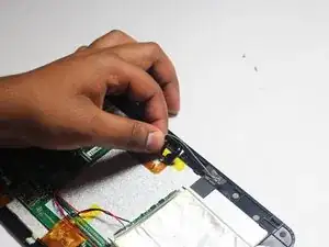
    • Follow the camera unit back to the motherboard.

    • Use the spudger tool to remove the camera.

  9. 3kdrevvXeih5RjZM
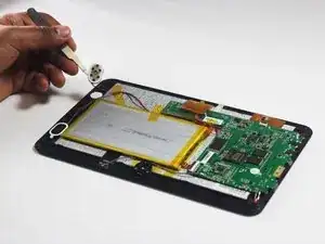
    • Remove the Speakers

    • Use the tweezers to remove the speakers from their compartments.

    Should you have two photos? Is it clear where you removed the speaker from?

    Should you note here that the speaker has wires that will also need to be removed?

    Do you ever mention the tape?

    Lisa Shaver -

  10. 2mNLUOQfeb6lRBpp
    2mNLUOQfeb6lRBpp
    YpSeBxMVtvvPM1dS
    • Desolder the 4 Speaker Wires

    • These wires connect the speakers to the motherboard. They are the thinnest wires.

    • If you're unfamiliar with soldering or desoldering check out this guide.

    • Be sure to wear protective eye wear. Also, keep in mind that the soldering iron will become extremely hot.

    Again, you are telling what to do, not how to do it.

    Lisa Shaver -

  11. 4KkYtYZ5sDuRxhTJ
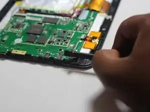
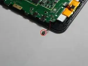
    • Remove the microphone from its compartment.

    • The microphone is located toward the bottom left corner of the device (assuming the speakers are located on the right side of you).

  12. uuwpidNtg4KGphrP
    uuwpidNtg4KGphrP
    cQukMeZRBJaJ6ZnU
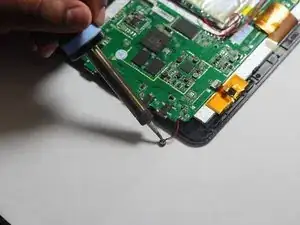
    • Use the soldering iron to remove the wires connected to the microphone.

    • If you're unfamiliar with soldering or desoldering, check out this guide.

    • Be sure to wear protective eye wear. Also, keep in mind that the soldering iron will become extremely hot.

  13. UulX6mcMjYLRuOtU
    UulX6mcMjYLRuOtU
    Lj33b3PSPDel5cOe
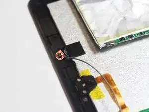
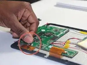
    • Use a soldering iron to desolder the region circled in red.

    • If you're unfamiliar with soldering or desoldering check out this guide.

    • Be sure to wear protective eye wear. The soldering iron will become extremely hot and a potential danger, so be aware of your surroundings.

  14. ITLcwtiXNnAAbjO4
    ITLcwtiXNnAAbjO4
    2wSaXGSmOXKPChSJ
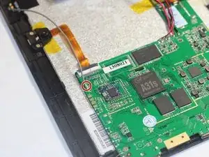
    • Desolder the FM antenna from the motherboard.

  15. 11FF5kZOTDP31VSL
    11FF5kZOTDP31VSL
    B2Q16EMW6TPfC6w5
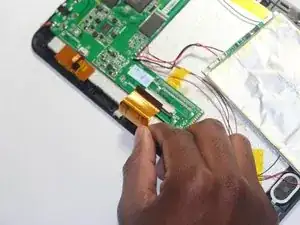
    • Remove the large ribbon cable from the socket that attaches it to the motherboard.

    • Pull down on the dark grey sliders located on both sides of the ribbon cable to release it.

  16. V2nBwtUbOIUYGBXJ
    V2nBwtUbOIUYGBXJ
    PWxlOIV5wQHAEAbM
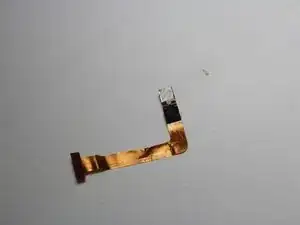
    • Remove the small ribbon cable from the socket that attaches it to the motherboard.

    • Flip the dark grey latch to release the ribbon cable from the motherboard.

  17. 3orZdllOJi12WJQE
    3orZdllOJi12WJQE
    VufppG2r3WPR6hvl
    pHfkssKcLZlMKm3U
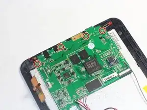
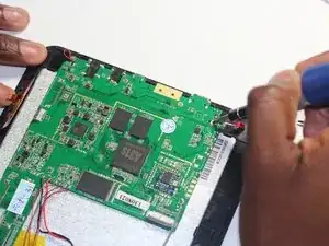
    • Remove the four Phillips #00 screws attaching the motherboard to the device.

Abschluss

To reassemble your device, follow these instructions in reverse order.
Harris Dagha

Mitglied seit: 26/03/15

866 Reputation

0 Kommentare