Einleitung

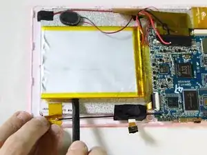
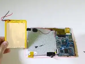
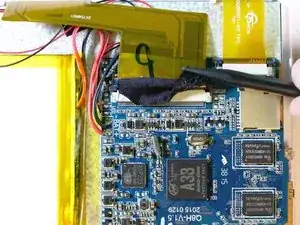
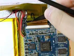
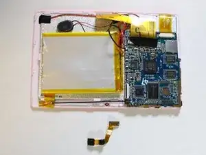
Before you begin to replace the screen of your Tagital T7X be sure to review the Troubleshooting page to ensure that this is a valid solution. The screen will need to be replaced if the touch screen is not responsive or does not display anything. Some soldering is required. Good luck!

  1. ChC6hEvPhUmGjMAN
    ChC6hEvPhUmGjMAN
    VjJ3JNVSQMKvB2fu
    S6mNGUyuSHejCWoO
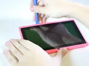
    • Place the Tagital T7X on a sturdy surface.

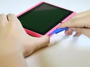
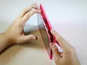
    • Insert the plastic opening tool into the crack and pry open the tablet. Move the tool along the edge, while continuing to pry up the casing.

  2. PH11kvlIWNI3wH5k
    PH11kvlIWNI3wH5k
    mOZrSoOLvMWvXdo2
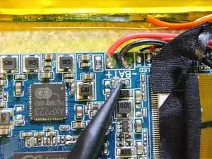
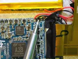
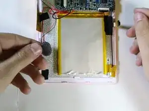
    • Follow the attached wires to the positive and negative connections.

  3. QEVQgUrJpew6xtUy
    QEVQgUrJpew6xtUy
    sePaAqENEplKnqKm
    11uDlhjdaf6Kdwhy
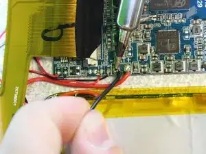
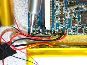
    • The soldering iron can destroy components on the motherboard. Only touch the soldering iron to the solder already on the board.

    • Touch the tip of the soldering iron to the solder connecting the negative wire.

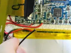
    • Pull back on the wire with the iron in place, removing it from the hot solder.

    • The solder will be melted almost instantly. There is no need to hold the iron on the solder for more than a second or two. Visit iFixit's soldering guide for more info.

    • Repeat this step for the positive wire.

  4. Iopo4CQ6hVJVnmoa
    Iopo4CQ6hVJVnmoa
    xwhe1XIhpQgMYuwJ
    ZSUJMKaKBxEMbYTl
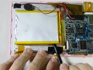
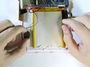
    • Use the nylon spudger to pry the battery from the back of the screen. Work your way around the edges, similar to opening the casing.

    • The adhesive used to hold the battery down is very strong. Don't be afraid to use some force.

  5. 3MBbw2Yw1WD32AVc
    3MBbw2Yw1WD32AVc
    obGwodhACWNo5wGq
    CEJ1YyuNXLFAFBvs
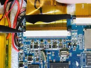
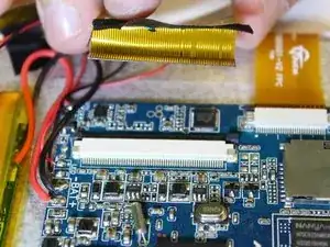
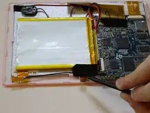
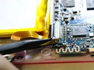
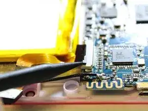
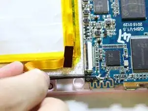
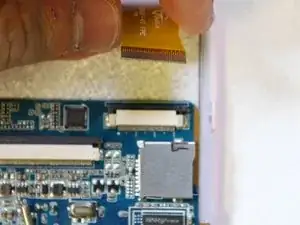
    • Remove the ribbon cable on the top left corner of the mother board.

    • Gently lift the black tape up to see the ribbon cable socket.

  6. aUgdetK4poPcQcAV
    aUgdetK4poPcQcAV
    51CKjNfG4gniuZoR
    uQsS6CtMQDvdT5jU
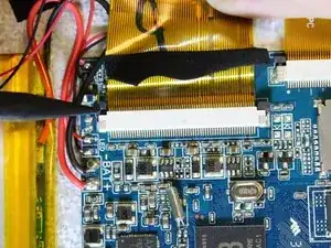
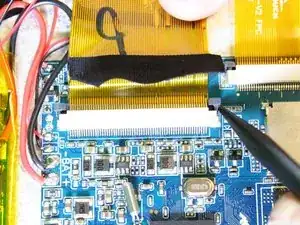
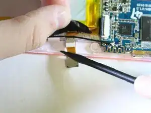
    • Push both side buttons away from the socket by using a spudger.

  7. g5gYEYJCr5GXlGW6
    g5gYEYJCr5GXlGW6
    51FnIkGd4e1KBkbU
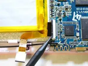
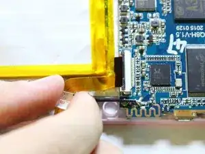
    • Gently pull the ribbon cable away from the socket.

    • Don't be afraid to use some force for this step.

  8. tdTPjaZcguPCukTu
    tdTPjaZcguPCukTu
    tBOYvwsWn1KfIWAw
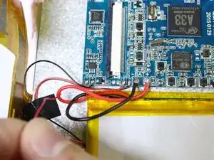
    • The soldering iron can destroy components on the motherboard. Only touch the soldering iron to the solder already on the board.

    • Touch the tip of the soldering iron to the solder connecting the positive (red) wire.

    • Pull back on the wire with the iron in place, removing it from the hot solder.

    • Repeat this step for the negative wire.

    • The solder will be melted almost instantly. There is no need to hold the iron on the solder for than a second or two. Visit IFixit's soldering guide for more info.

  9. FXmvKMON1XmFokfx
    FXmvKMON1XmFokfx
    TEi4ArWFunSXRvOl
    • Remove the speaker from the motherboard.

  10. 3P1KEUDfHRmZhYsb
    3P1KEUDfHRmZhYsb
    gi1OmwlPgWowPUN2
    hBbGp2LesGhn5JLP
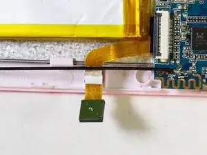
    • Use a spudger to hold the cameras in place.

    • Gently pull the black tape away using your finger.

  11. 4nYsPQAVyK21UTDu
    4nYsPQAVyK21UTDu
    XU1blHLPYNB33LIl
    UhJIaQdFkuRVUAF2
    • Remove the ribbon cable from the motherboard.

    • Use a spudger to lift the two tabs, freeing the ribbon cable from the socket.

  12. MenXXLGOBXyXhuJQ
    MenXXLGOBXyXhuJQ
    DPZYnCNtwnZVdvBU
    kuZd4AHlM4uQJMPA
    • Gently pull the ribbon cable away from the motherboard.

    • Don't be afraid to use some force to pull the ribbon cable.

  13. QJADpoJPLDKOYXxw
    QJADpoJPLDKOYXxw
    ySNJShPCXPISmNqY
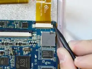
    • Next we will disconnect the digitizer ribbon cable from the motherboard.

    • Using the black spudger, gently push the tabs on each side of the socket to free the ribbon cable.

  14. yjKVPEZZQgGnAhpn
    yjKVPEZZQgGnAhpn
    HBdDtlSHECAUtKJf
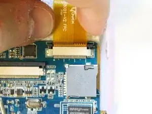
    • Gently pull on the ribbon cable, separating it from the socket.

  15. 3uHFrG1p5jkcbL5X
    3uHFrG1p5jkcbL5X
    hiEnRJk5VddAvosd
    VCBPdiMGJEwLbeoH
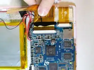
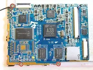
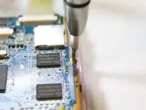
    • Next, we will unscrew the three PH#0 screws anchoring the motherboard into the case.

    • You will need the Phillips Screw #0 to remove the screws of the motherboard.

    • Using the screwdriver, with the PH#0 attachment, carefully unscrew the screws of the motherboard in order to remove it from the device.

  16. FGOKIFKYDTqeHRvD
    FGOKIFKYDTqeHRvD
    ZvdWO3PorUZIFqHG
    VjklZ5LpMRIwK3hn
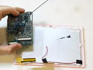
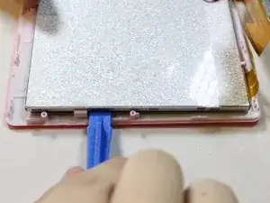
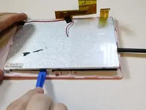
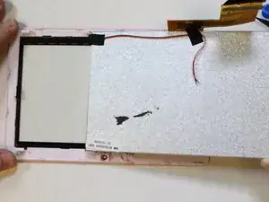
    • Insert a plastic opening tool where the screen connects with the front face of the case.

    • Use a spudger to keep the screen from falling back into the casing.

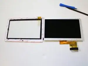
    • The screen will slide out once the connection has been nudged on three sides.

    I looked for these instructions everywhere and didn’t find it until after I spent 5 hours working on it. And all these steps are accurate and easily understood.

    sooboo8 -

Abschluss

To reassemble your device, follow these instructions in reverse order.
Garven Dabady

Mitglied seit: 10/02/16

370 Reputation

0 Kommentare