Einleitung

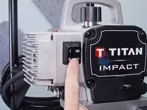
Use this guide to replace the pressure adjustment assembly in your Titan Impact 410 Airless Sprayer.

  1. wu65Kb5OrpKcbGWN
    wu65Kb5OrpKcbGWN
    IUL6c4WgM6oJNQWK
    • Before you begin, make sure to follow the pressure relief procedure documented in the user manual before powering down the paint sprayer and disconnecting the pump.

    • Turn off and unplug the sprayer.

  2. 2shjbtSQuPXNqtFF
    2shjbtSQuPXNqtFF
    HRrWtWyBslT36Mjv
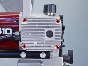
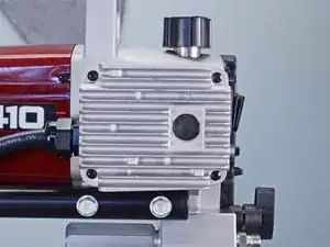
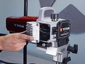
    • Use a Phillips driver to remove the four 12 mm-long screws securing the motor controller assembly.

  3. FHXXQLVEauhcAcUB
    FHXXQLVEauhcAcUB
    PvAMLfBuFMoqRD3V
    FR2dZXApPEoP4r33
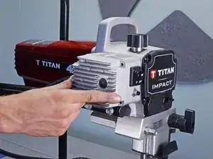
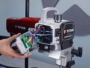
    • Don't try to remove the motor controller assembly completely, as it's connected to the body with cables.

    • Pull the motor controller assembly out and hold it to the side, exposing the cables.

  4. taKk2RF2GTm6w5ea
    taKk2RF2GTm6w5ea
    2tNAGs6YpAGcGgsK
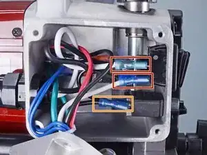
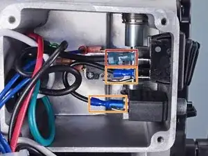
    • Use a pair of needle nose pliers, or your fingers, to disconnect the two spade connectors from to the on/off switch.

    • Disconnect the one spade connector on the circuit breaker.

    • Note the order of the cables and their connectors to help with reassembly.

  5. E3xZIIjPNxZ6txxF
    E3xZIIjPNxZ6txxF
    B6LvIbQdg44CrJYd
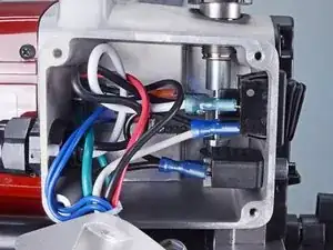
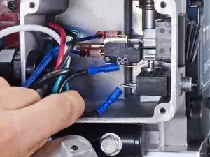
    • Disconnect the remaining spade connector from the on/off switch

    • Disconnect the jumper spade connector from the on/off switch and the circuit breaker.

    • The black jumper cable with the dark blue connectors isn't attached to the rest of the assembly.

    • Note the order of the cables and their connectors to help with reassembly.

  6. A2j2JEBHjVT16lZF
    A2j2JEBHjVT16lZF
    2fuOaVdf3BBPv1YA
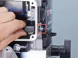
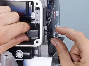
    • Use your fingers to unscrew and remove the circuit breaker nut.

    • Remove the circuit breaker.

  7. XE4J2XcVAEoMbnRN
    XE4J2XcVAEoMbnRN
    LmdEDQcynPrQgyAH
    GLgSHdtQR6sh6Apo
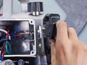
    • Use a flathead screwdriver to depress the locking tabs located on both the top and bottom of the on/off switch.

    • While depressing the tabs, push the on/off switch out through the cutout.

    • Remove the on/off switch.

  8. S2wB2XOBbQA5FIcx
    S2wB2XOBbQA5FIcx
    jQdeTZpUpEtlx1Hc
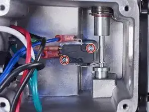
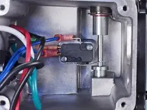
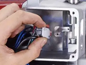
    • Use a Phillips driver to remove the two 17 mm-long screws securing the contact switch.

  9. orvUHww4yRulqNNJ
    • Pull the contact switch away from the plunger and place it on the floor of the housing.

  10. NwNNMdpIxdjNAWGJ
    NwNNMdpIxdjNAWGJ
    EyM2tIedkcWbjepF
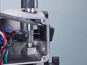
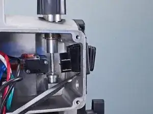
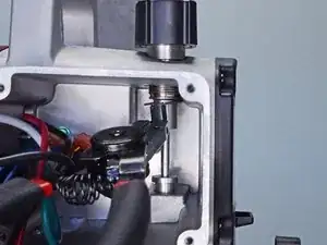
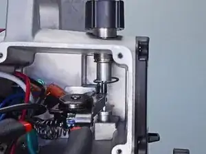
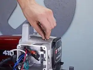
    • Use snap ring pliers to remove the retaining ring from the top of the plunger.

    • During reassembly, install a new ring with the flat side facing down.

  11. fcSW2tJKQUBTMQJW
    fcSW2tJKQUBTMQJW
    fW6wY4QRrqH1Od1N
    3ZgBixtxPTAG3ahB
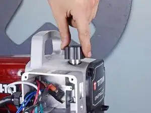
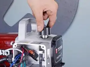
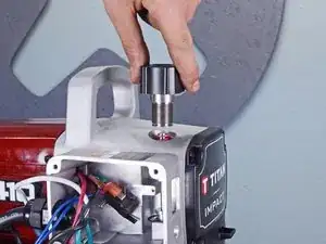
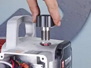
    • Loosen the pressure control knob.

    • Remove the pressure control knob.

  12. ySPxdhY5gJcCvip4
    ySPxdhY5gJcCvip4
    u1BHcrsO1N5uSWFT
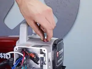
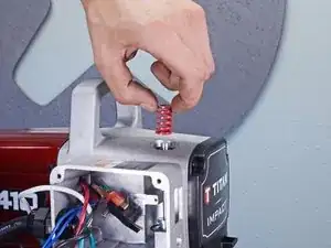
    • Remove the pressure adjustment spring.

  13. JbcZyxclVGtKuGto
    JbcZyxclVGtKuGto
    aEmRYgTogWPhsSoB
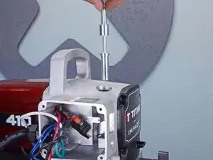
    • Remove the plunger.

Abschluss

To reassemble your device, follow these instructions in reverse order.
Alex Diaz-Kokaisl

Mitglied seit: 16/01/22

69204 Reputation

0 Kommentare