Einleitung
Werkzeuge
-
-
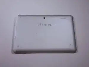
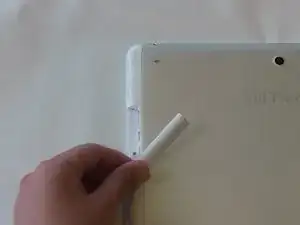
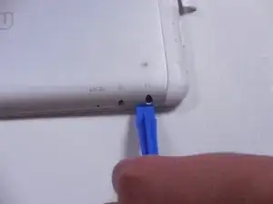
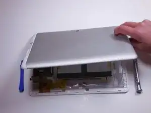
Use the plastic opening tool between the back plate and front plate to pry the back plate off; start at the headphone jack.
-
-
-
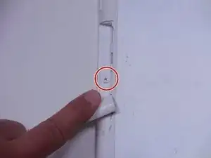
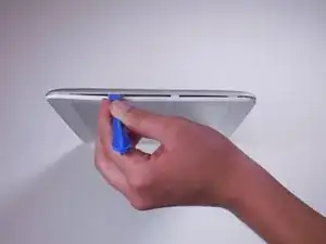
Move around the device with the plastic opening tool pushing down to release the back plate from clips.
-
-
-
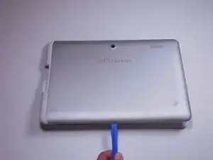
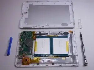
Once you’ve moved around the whole device with the plastic opening tool, the back plate will completely release from the rest of the device.
-
-
-
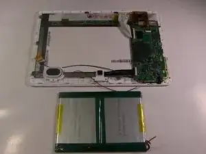
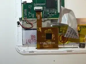
The battery rests flat on the inside surface of the tablet. It is a rectangular shape and has blue and yellow tape.
-
-
-
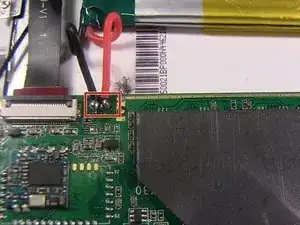
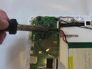
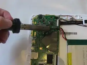
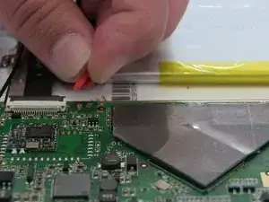
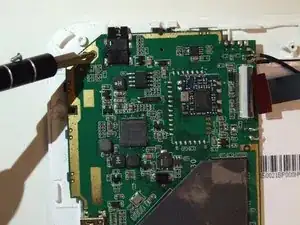
Work the soldering gun on the red wire where it is connected to the motherboard. it should release from the motherboard.
-
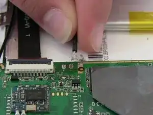
Work the soldering gun on the black wire where it is connected to the motherboard. It will release from the motherboard.
-
-
-
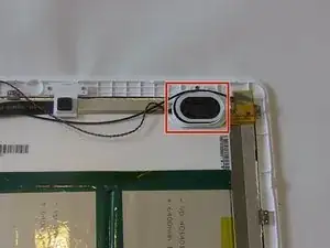
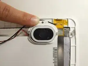
With the face of the device down, the speaker will be in the upper right corner. The black oval shaped object.
-
-
-
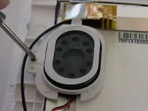
A phillips 3.88 mm screw will be holding the speaker in place.
-
Use a PH000 screwdriver to remove the screw.
-
-
-
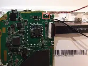
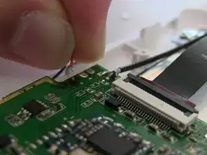
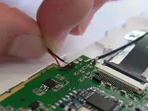
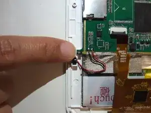
The speaker will be connected to two wires; one black and one red. Both run to the motherboard.
-
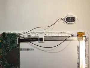
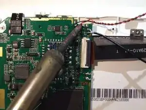
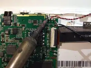
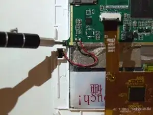
The wires will need to be soldered off the motherboard.
-
Locate where both wires are soldered to the motherboard.
-
Review How to Solder Here
-
-
-
Work the iron where the black wire is soldered.
-
The black wire will release from the motherboard.
-
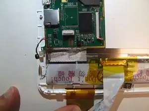
After both wires have been soldered off, the speaker will release from the device.
-
-
-
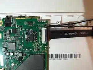
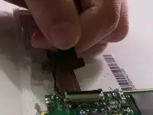
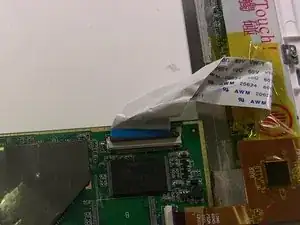
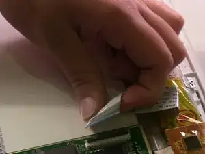
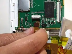
Remove the black ribbon connector. Flip the black portion of the connector upward.
-
Pull on the ribbon to remove from the connector.
-
-
-
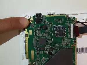
A 2.88 mm phillips head screw will be located in the upper right hand corner of the mother board.
-
Use a #00 screw driver with the PH000 screw head to remove the screw.
-
-
-
A 2.88 mm phillips head screw will be seen on the lower left hand corner.
-
Use the #00 screw driver with the PH000 screw head to remove the screw.
-
-
-
On the bottom of the motherboard, a strip of gold tape will be seen holding the it to the device.
-
-
-
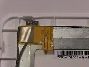
A black wire will be connected to the device and ran to a strip of orange tape on the upper right hand corner of the device.
-
Remove the tape that holds the wire down.
-
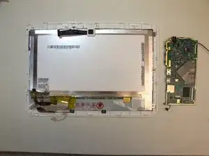
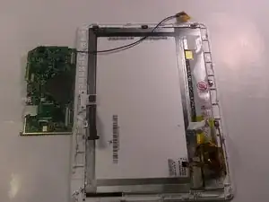
The mother board will remove from the device.
-
To reassemble your device, follow these instructions in reverse order.
