Einleitung

If the screen/digitizer on your Trio Stealth-10 is no longer functioning, replacement isn't difficult and this guide will give you the step by step procedure to do so.

  1. eCJR1dIQ4GKUFJQq
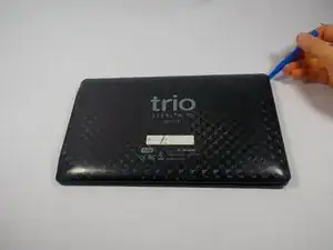
    • To remove the back panel, you will need to use a plastic opening tool and slowly separate the back panel from the device.

  2. GRsNNsbBTtTuScXX
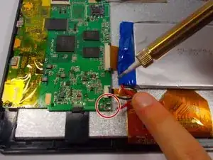
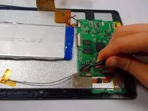
    • This step will require soldering. If you are unfamiliar with soldering then we recommend that you get help from another person or use the soldering guide made by Ifixit to help.

    • Solder the connections off for the battery.

  3. uFJXhVii4siU4HSV
    uFJXhVii4siU4HSV
    BrQkQoLDZQbP4ruo
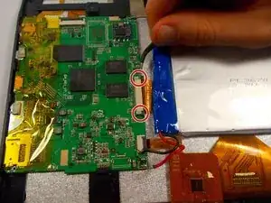
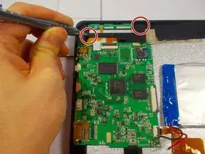
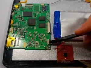
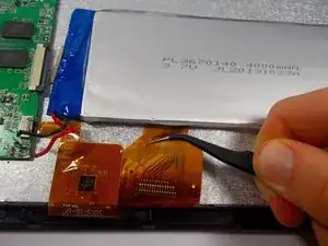
    • Disconnect the screen/digitizer connection. Use tweezers and pull each grey end of the connection until there is a small gap between the grey and white on the connector to the motherboard. The connection should be easily removable.

    • Pull the cable away and clear from under the battery to avoid damage to the connection.

  4. tnXy4BeukhTqcTxM
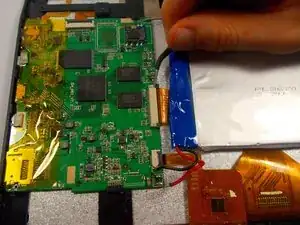
    • Pry battery up from adhesive. Use a type of adhesive remover. Nail polish remover works well.

  5. NAH5mlWhF5eZpTfe
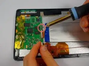
    • This next step will require you to solder a couple of wires off the motherboard. We recommend you get someone to help you if you are unfamiliar with soldering or use Ifixit's Soldering guide to help you.

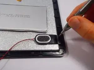
    • Next you must solder off the wires that connect the speaker to the motherboard.

  6. vQMM11TiXtwHdCXi
    • Next you will need to remove the two screws attached to the speaker. If you have a 54 bit Driver Kit use the Philips Head 0 (or PH 0) head to remove the two 4mm screws.

  7. KURv4PeYEfGOhpSH
    • Next use your PH 0 to remove the two 4mm screws to detach the camera support fixture.

  8. VQYhhQjdDXHmfieu
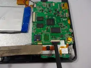
    • Disconnect the camera from the mother board. Use a spudger and lift the grey latch until it is facing up then pull out the connection for the cameras.

  9. cjKj6fooDZQwvsNU
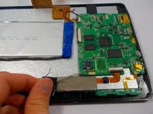
    • Remove the first layer of tape above camera cable connection slowly.

  10. TjiAM5cYkfPb2wgp
    • Remove the second layer of tape above camera cable connection gently and remove the cameras from the device.

  11. NP4LRowLDBtbhnnS
    • Use your spudger to disconnect the screen/digitizer connection from the motherboard.

  12. gSg4tdFNSC5FaoBO
    gSg4tdFNSC5FaoBO
    KBQetiFujAdd1CKB
    • Use a pair of tweezers to grasp the screen/digitizer connection gently and remove each accordingly.

  13. wxyPnNINoDyv26Gm
    • Grasp the EDC tape with your tweezers and lift it off gently from the motherboard and set aside to be reused.

  14. FGvrRGPYZU2NVmmB
    FGvrRGPYZU2NVmmB
    wRGThj4126eFKw6Z
    • Use a Phillips #0 to unscrew the 4mm screws from the motherboard fixture.

  15. TYl2lZFAdMtp212X
    • Be sure that all the connections to the motherboard are disconnected. Proceed to remove the motherboard by slowly tilting it away from you and then lifting it straight up.

  16. VkCWAP4ZseMA3aLE
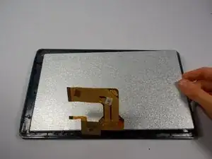
    • Remove all disconnected components and remove screen/digitizer.

Abschluss

To reassemble your device, follow these instructions in reverse order.
Daniel Coleman

Mitglied seit: 29/10/15

640 Reputation

2 Kommentare

I can fix them like its no $@$* I want every tool to fixs them I use tool but I want the right ones I like making $$$$$

bkress81 -

I want all smart TV that are broke I like working on them I have for many years

bkress81 -