Einleitung

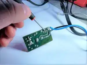
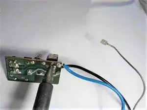
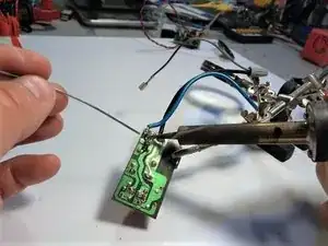
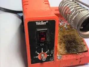
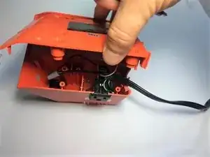
The Weller WLC100 soldering station adjustable heat dial often goes bad because of a failure of the TRIAC switch on the adjustable heat board. To fix the adjustable heat dial we can replace this inexpensive switch. We will need to use the existing Weller iron to de-solder the TRIAC switch and re-solder in the new switch. However, if you own a Weller you most likely have experience using soldering irons, and this process presents little opportunity for injury.  This repair should take less than two hours depending on skill set. There is always a possibility of being burned when using a soldering iron. Care must be used when handling hot soldering irons.

  1. ZJCN21RT1TGQVMKi
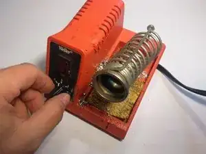
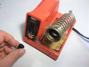
    • Remove the knob from the adjustment dial.

  2. IHn5PiuRQUUln1KD
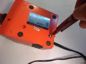
    • Remove two 8.6 mm Phillips #1 screws from soldering station bottom.

  3. pycNDI4BosWWFyiJ
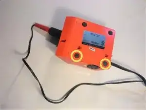
    • Remove the rubber feet to access the remaining screws.

  4. Bw1CdBqOkdwoQNPn
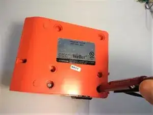
    • Remove the remaining two 8.6 mm Phillips #1 screws from soldering station bottom.

  5. 6rVjjA4DKVAGoDqs
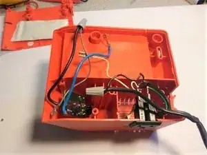
    • Separate the bottom and top half of the soldering station.

  6. IUKxQITfaIhvGldW
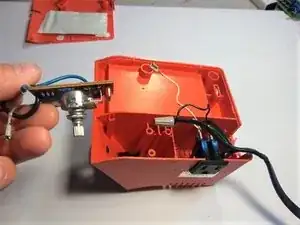
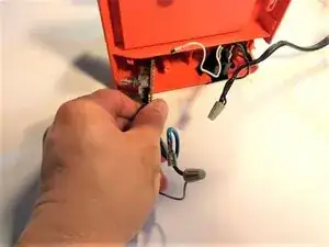
    • Remove the adjustable heat dial board.

  7. GtxIeTmFBvOQqCL1
    GtxIeTmFBvOQqCL1
    FLR3MX5IZQiHvsRZ
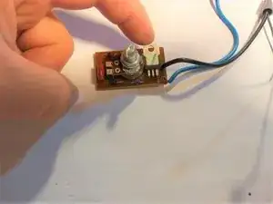
    • Orient the new TRIAC switch the same way as the old TRIAC switch is located.

  8. rYNeJ4juavm2huEK
    rYNeJ4juavm2huEK
    1lOO1jmG56JoLwHH
  9. oe2BvMkPmM4H2eSF
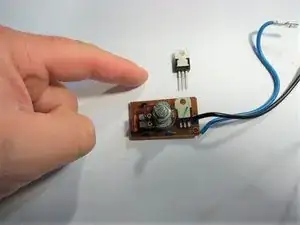
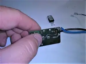
    • Remove the TRIAC switch when all the solder is removed from the pins.

  10. mTjfSXOWfjLAKeWe
    • Insert the new TRIAC switch into the three holes left when you removed the old TRIAC switch.

  11. yaxogWaClHBbXxyN
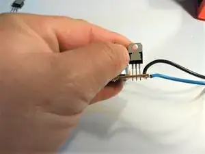
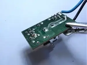
    • Solder the new TRIAC switch onto board.

  12. mSFaiTkNLpSFnKBI
    • Verify all three pins are soldered in and the solder is not touching the other pins.

  13. 6RMtMxuZDUAVwFSN
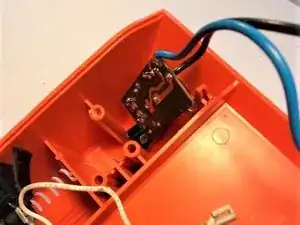
    • Re-install the board into the soldering station.

  14. sGAbL1BHgIK3NKwM
    • Push the knob into the hole so that is it protruding out of the other side.

  15. QechSLeFNixH2WAA
    • Verify the knob is sticking out of the other side of soldering station.

  16. lmijKqpALWxFGaFf
    • Replace the dial onto the knob.

  17. SAPqSqBHgHdUEIv5
    • Replace the bottom and replace all four screws and rubber feet, reversing steps four though two.

Abschluss

To reassemble your device, follow these instructions in reverse order.
Terence Ryan

Mitglied seit: 17/02/21

265 Reputation

0 Kommentare