Einleitung

If you are experience poor sound quality, or the sound is not properly dispensing, replacing the woofers can resolve these issues. This guide provides the step by step procedure to replacing this part.

  1. VMqfKshwhAtRbNLJ
    VMqfKshwhAtRbNLJ
    aQkWSndBksivJDgY
    mpKVVSyLDySMsXFT
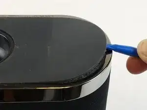
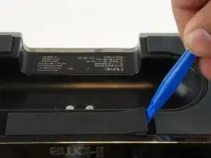
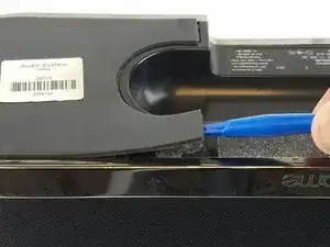
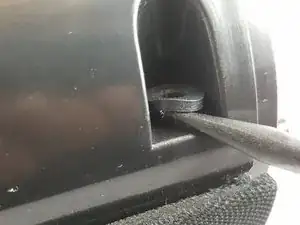
    • Remove the rubber from the bottom of the speaker, use a medium blue plastic spudger to gently work its way under the rubber and slowly peel off for each of the three feet. The order does not matter.

  2. UxgmG3bQu3MDWg1v
    UxgmG3bQu3MDWg1v
    ymlPcBqKpYEGjrYO
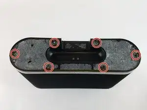
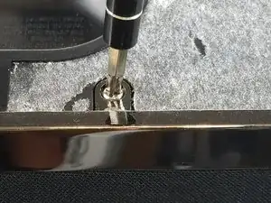
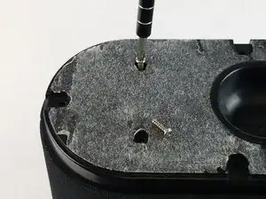
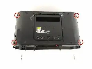
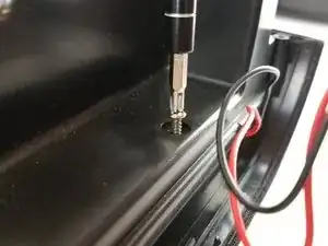
    • Remove the six 11 mm Philips #1 screws found underneath the foam to remove the steel outer metal frame.

    • Once the screws come off, keep them safely off to the side.

  3. LlASWNUXjOWbnJOp
    LlASWNUXjOWbnJOp
    EMFYAghAhTAjZxP3
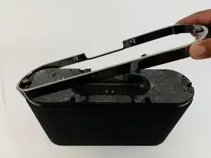
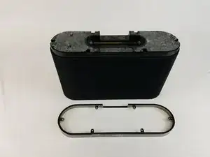
    • Remove the metal frame gently and set aside.

  4. SUjlcpgxrotvhZcZ
    SUjlcpgxrotvhZcZ
    s3hY6VHiuQZNRe2j
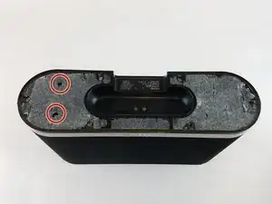
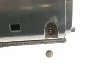
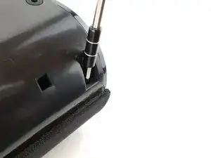
    • Remove the two remaining 11 mm Philips #1 screws holding the base and set them aside.

  5. XSEVEDveVX1anmrQ
    XSEVEDveVX1anmrQ
    3lrU2wepcHeHrDHh
    QX2MJSte3vcmYAld
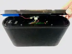
    • Lift the base up gently keeping in mind that the base is connected with wires to internal parts of the speaker.

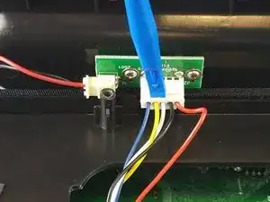
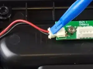
    • Disconnect the white bundled cable connector attached to the charging node using a spudger. The base of the speaker is now free to be removed.

  6. JHTY31AEUbjeILnK
    JHTY31AEUbjeILnK
    K2Evv2JOOSLUNaG4
    KuL65qa1YkOPsPeP
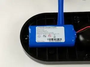
    • Remove the white power cable connector that connects the charging node to the battery, using the plastic spudger.

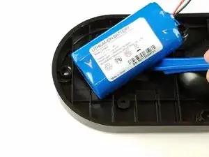
    • Pry the battery off using the plastic spudger.

  7. MmErokB21ZdIq2KJ
    MmErokB21ZdIq2KJ
    KLeuBy2bRQlTbJUU
    WXQ5BQSeJqBRIBrW
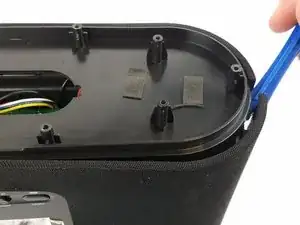
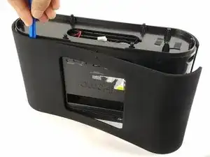
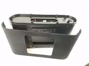
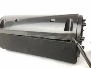
    • Pry off the mesh frame from the back side of the speaker with a plastic spudger until you hear a click noise when the clip is removed.

  8. NDDm5QXgZVcO3KLE
    NDDm5QXgZVcO3KLE
    tMFMOPqvOVnmqbYo
    rmOGibGEmDcnU5gx
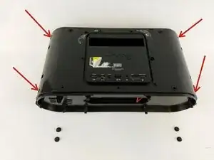
    • Use a plastic spudger to remove the rubber grommets from the four corners of the speaker underneath the mesh frame.

  9. j3nwAurWoxKBSw4S
    j3nwAurWoxKBSw4S
    DaFqBLGsFc4tVERv
    vp5quSd1NTe5B4MO
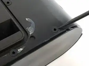
    • Remove the four 11 mm Philips #1 screws from beneath the rubber grommet that was removed from the previous step in all four corners.

  10. Y12furRR6utWMO6s
    Y12furRR6utWMO6s
    WAhFJGrQNjJqILjb
    ZPiESLONFLPQAcMn
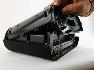
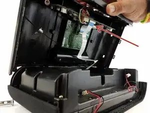
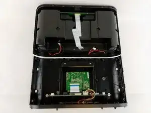
    • Separate the mesh frame and plastic frame by placing the spudger in between them.

    • Do not pull the two pieces since the two pieces are held together with the ribbon cable.

  11. yJ3wSPY2JroOptnP
    yJ3wSPY2JroOptnP
    lZAWIvXCYPxrdM2s
    cJ5yUcaYdTjbwuOC
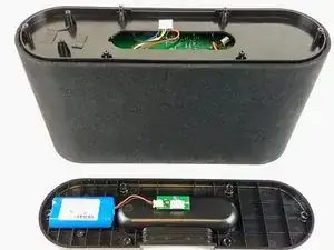
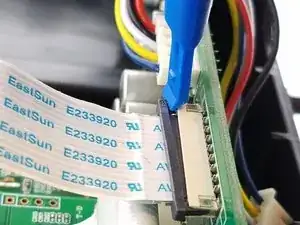
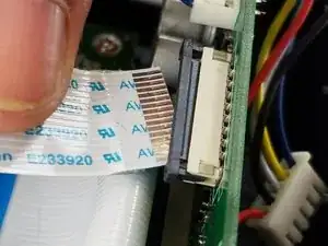
    • Remove the ribbon cable by pulling the black clip towards the cable, then gently pull the ribbon cable to fully separate the mesh frame and plastic frame.

    • The black locking clip will only move about 2mm out.

  12. beGa5LuGFRdTAMSr
    beGa5LuGFRdTAMSr
    5NpeN3qCp2BxV2vv
    Qoc6vHYATHIA41TK
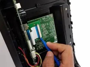
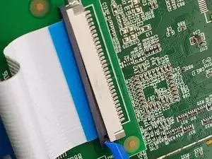
    • Remove the second ribbon cable that is connected to the main circuit board and the WiFi adapter.

    • The black locking clip will only move about 2mm out.

  13. qN2UKsAI5XdB4RWM
    qN2UKsAI5XdB4RWM
    CfBETh1aqEOyxmJX
    KwOGaEuC1DRgFRsC
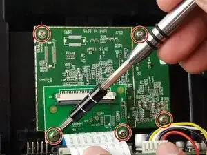
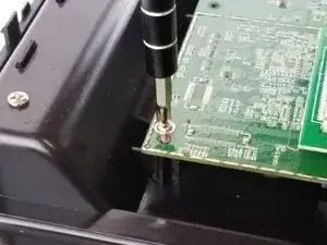
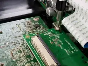
    • Unscrew the five 11 mm Philips #1 screws found on the outside of the circuit board.

  14. WhENdJaY4ondOpZo
    WhENdJaY4ondOpZo
    NvqpJZcGeHP4HyuG
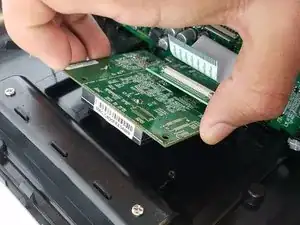
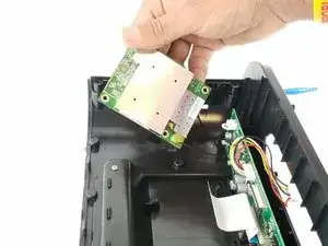
    • Lift the circuit board to expose the wifi antenna wire.

  15. fpVCpjyQONRy6Q5c
    fpVCpjyQONRy6Q5c
    vCsXGRvCm6GdEHYJ
    2x6LQ6QZPbOLrjop
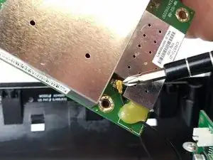
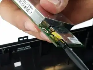
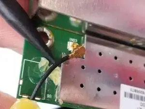
    • Pry the glue and unclip the wifi antenna plug from the circuit board.

  16. neCLFRuZYBl1S1Q1
    neCLFRuZYBl1S1Q1
    NIquUDPowJCQPas4
    YI6VTIEfmbBuOcui
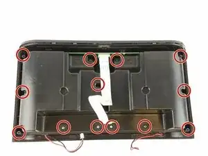
    • Remove the thirteen 11 mm Philips #1 screws from the perimeter of the plastic case.

    • Remove the screws from the center of the plastic case as well.

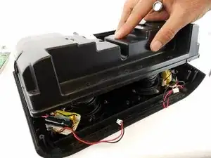
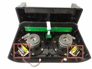
    • Lift the case up to expose the Woofer, Tweeter, and filter.

  17. KxeeuK6PNivJfuVy
    KxeeuK6PNivJfuVy
    4gQv3PP26PWJ1fKM
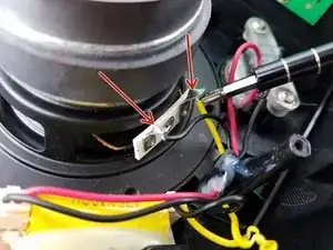
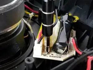
    • Desolder the wires going from the woofer to the filter.

    • Some tips on soldering can be found by clicking this link. Wie man Lötverbindungen herstellt und entlötet

    • Make sure to remember the orientation and color coding of the wires before desoldering.

  18. yE3OxfXlZGZTAiXL
    • Remove the two 11 mm Philips #1 screws holding the filter to move it out of the way.

  19. f4m4NIaAswUQdLYp
    f4m4NIaAswUQdLYp
    SpptGXuyZrIrWaNm
    nlLBcYHqfvvybLtS
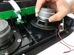
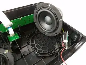
    • Remove the six 11 mm Philips #1 screws from the perimeter of the woofer.

    • Gently lift the woofer from the plastic frame.

Abschluss

To reassemble your device, follow these instructions in reverse order.
Victor Germino

Mitglied seit: 14/02/17

828 Reputation

0 Kommentare