Einleitung

Use this guide to remove your heat sink.

  1. Aew5W1SyZmXwiIpC
    • Before you work on the computer, unplug the computer and press the power button for 20-30 seconds to drain the stored energy in the power supply.

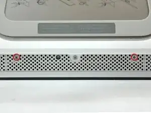
    • Loosen the two Phillips screws securing the access door to your iMac.

    • These screws are captive in the access door.

  2. sgn5MWowvBqWBHTa
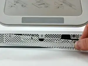
    • Remove the access door from your iMac.

  3. VSg2SDmHlb6LeIcc
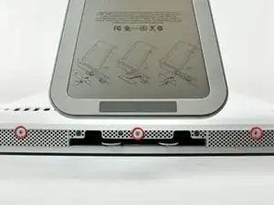
    • Remove the three T8 Torx screws securing the front bezel to the rear panel.

  4. yDINeBPXAToRUhia
    yDINeBPXAToRUhia
    MHTpeXSgmBpLcfmO
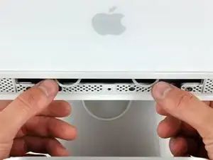
    • Orient the iMac face-up, on its backside.

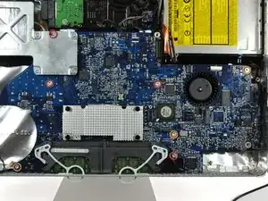
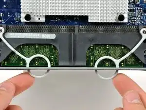
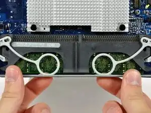
    • Use your thumbs to press both RAM arms in past the front bezel for enough clearance to lift it off the rear case.

  5. yYxPBhiYPLBWhcPJ
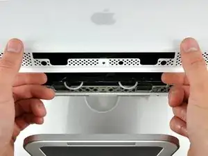
    • While holding the RAM arms in with your thumbs, lift the lower edge of the front bezel enough to clear the rear case.

  6. hlSTYKaegjL4nCbA
    hlSTYKaegjL4nCbA
    RlBPIITef4YhTLWJ
    DBMIAdUDgFvhGqgo
    • Re-orient your iMac so it sits upright on the stand.

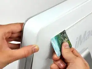
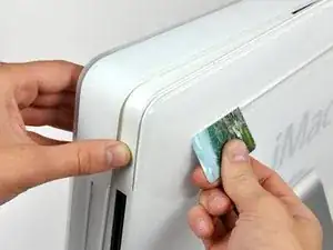
    • Insert a plastic card up into the corner of the air vent slot at the top of the rear case.

    • Push the card toward the top of the iMac to release the front bezel latch.

    • Pull the front bezel away from the rear case.

    • Repeat this process for the other side of the front bezel.

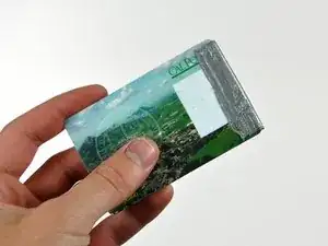
    • It may be necessary to apply several layers of duct tape to the top of the access card to aid in releasing the latches.

    • If the bezel refuses to release, try pressing the lower edge back onto the rear case and repeat this opening process.

    Using a strongish magnet will grab and release the latches.

    darkstar448 -

    Zitat von darkstar448:

    Using a strongish magnet will grab and release the latches.

    Are you sure it's safe to do this? How close is the hard drive, won't magnets interfere with it?

    Sarah -

    It's almost certainly fine. Modern hard drives are very resistant to magnetic fields.

    zschroeder6212 -

  7. vgnHWHc6vItDofqx
    • Lay your iMac stand-side down on a table.

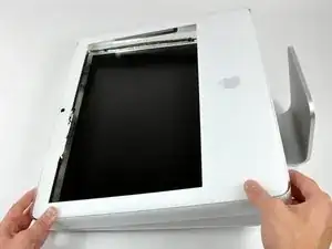
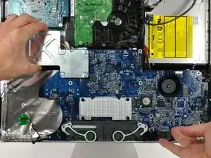
    • Lift the front bezel from its lower edge and rotate it away from the rest of your iMac, minding the RAM arms that may get caught.

    • Lay the front bezel above the rest of the iMac.

  8. Zk4f3XFRC5C4mRJl
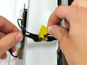
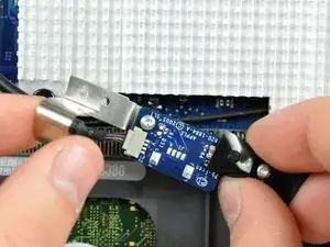
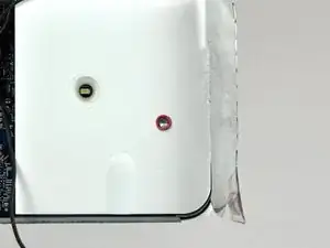
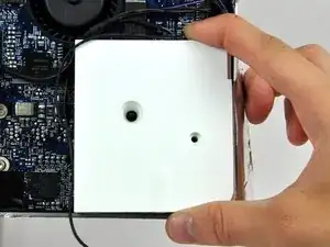
    • If necessary, remove the piece of kapton tape wrapped around the microphone and camera cables.

  9. mN1kWf5KYlsoZsjY
    mN1kWf5KYlsoZsjY
    SIofHNDswAVgClNU
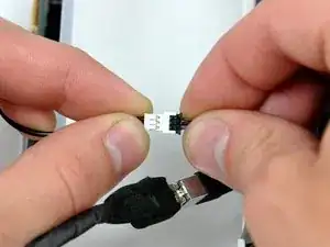
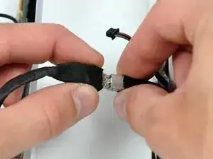
    • Disconnect both the camera and microphone cables.

  10. XTAmXZiwxZuVJ2oL
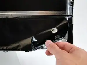
    • Peel back the aluminum EMI shield up off the lower three edges of the rear case.

    • It is not necessary to peel the EMI shield off the display.

    • We found it helpful to tape the EMI shield up against the display to keep it out of the way.

  11. FU4PPYZqLc6k5nlM
    FU4PPYZqLc6k5nlM
    qrxMpTi5IwNbCnn1
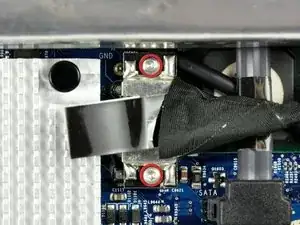
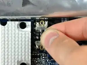
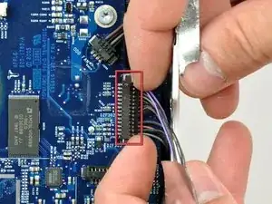
    • Remove the two 5 mm T6 Torx screws securing the display data cable to the logic board.

    • Using its attached black tab, pull the display data cable connector up off the logic board.

  12. rUbQ1QvF1STbgVYe
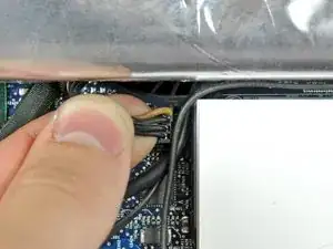
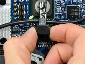
    • Pull the inverter cable connector up off its socket on the logic board.

  13. qZyvt35S4JSMt2FS
    • Peel back the aluminum EMI tape from the two vertical edges of the display.

    • During reassembly, it is helpful to use several small strips of tape to hold the EMI shielding along the left and right edges of the display footprint out of the way before lowering the display into the rear case of your iMac.

  14. nEUNOorKviDjPle1
    nEUNOorKviDjPle1
    AFFiNvESZibuONtV
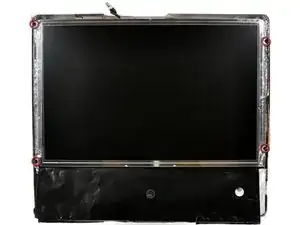
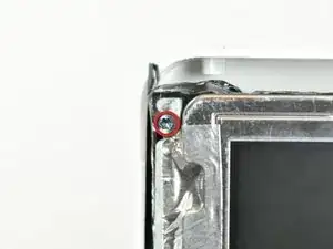
    • Remove the four recessed coarse-thread 7.5 mm T10 Torx screws securing the display to the rear case.

    • These screws are recessed, so a thin screwdriver such as this is essential for removal. Bit drivers tend to be too short for this application.

    No problem taking those screws off, HUGE problem trying to put them back in. Reassembling this step is a lot more complicated. Those 4 screws are impossible to reinstall if you don't have a magnetized screwdriver, which I don't.

    Javier Lopez -

    I used some 'chapstik' on my t10 driver and it held the screws long enough to insert them.

    aquarianknows -

    Zitat von javier:

    No problem taking those screws off, HUGE problem trying to put them back in. Reassembling this step is a lot more complicated. Those 4 screws are impossible to reinstall if you don't have a magnetized screwdriver, which I don't.

    Since I could not get a hold on a nice magnetized T10, I inverted the whole unit and worked upside down to avoid lost screws inside an iMac.

    Javier Lopez -

    Zitat von javier:

    Since I could not get a hold on a nice magnetized T10, I inverted the whole unit and worked upside down to avoid lost screws inside an iMac.

    Great, now my problem is to find a new cable that connects the panel to LB.

    I'm from Italy and nobody has got it .

    Please help me

    Thanks for all

    Carlo

    Lars -

    I found a group of wires not mentioned on the instructions along the underside of the display at the right. They were connected to something at the right bottom of the display near the white plastic piece. I am unable to raise the display more than a couple of inches at this side of it and am wondering what do do.

    modorange -

    The group of wires on the right side of the display is the inverter. Seems like a few steps were omitted, so I'll try to fill in the gaps. Use the T10 to remove the right speaker. It's the big white plastic squarish thing on the bottom right side of the iMac. It pulls stright up and you can either disconnect it or just leave it hanging. This should release the inverter cable from hanging up the right side of the display (it did for me, even disconnecting the inverter didn't help as the cable was under the speaker, the inverter doesn't need to be disconnected but it might be helpful to disentangle things and it's an easy one to take apart). The other step missing is to remove the perforated tape at the top of the LCD from the LCD, otherwise you can't really remove it. I found a spudger helpful for this task.

    I know it's a couple years since the OP posted, but hope this helps someone.

    Cheers

    Jeff Kamis

    maccentric -

    I've found that 'coating' the tip of the screwdriver with glue from a glue-stick will help to keep the screws from coming off of a non-magnetized driver.

    Henry in StL -

  15. guUDy2YCStILCV3I
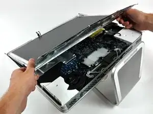
    • Lift the display from its lower edge and pull it toward yourself to peel it off the EMI shield attached to its top edge.

    • Be mindful of any cables that may get caught during removal.

  16. tkAYvuy1XAZfraoD
    tkAYvuy1XAZfraoD
    EMaALZawHNAtTZCj
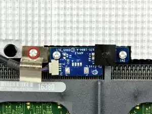
    • Remove the single 5 mm T6 Torx screw securing the IR board bracket to the logic board.

    • The IR board and cable finger are now free from the logic board and may fall.

    • Remove the IR cable finger and move the IR board, with cable still attached, out of the way.

  17. WYCon1iGHsE4Jrr4
    WYCon1iGHsE4Jrr4
    WL2BbXUW1ZN4uYpN
    • Remove the single 30 mm T10 Torx screw securing the left speaker to the rear case.

    • Pull the left speaker out of the rear case.

  18. SRkDC1k3kB51esny
    • De-route the left speaker cable along its path across the logic board.

  19. HG4ttFMUPpJA4OHu
    HG4ttFMUPpJA4OHu
    hYD3ctwkXEjBdSiE
    • Remove the single 17 mm T10 Torx screw securing the right speaker to the logic board.

    • Lift the right speaker out of the rear case and move it out of the way.

    • Both speakers are still attached to the logic board.

  20. KcxBSWVDAQcQQ5iT
    KcxBSWVDAQcQQ5iT
    s3hPatsfEUm2OVUl
    • If necessary, lift the IR board cable to free the left speaker cable pinned beneath.

    • Pull the speaker connector toward the top edge of your iMac to disconnect it from the logic board.

  21. yyc32QnejC5JL1e1
    yyc32QnejC5JL1e1
    Nj2LQ5NUMv4ICVaq
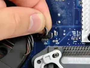
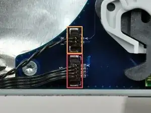
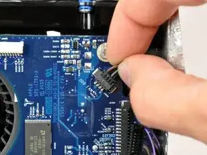
    • Disconnect the CPU fan connector from the logic board by pulling it straight up from its socket.

  22. yxkSYLKFqTeIKYoS
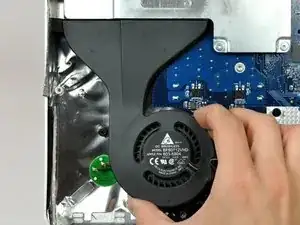
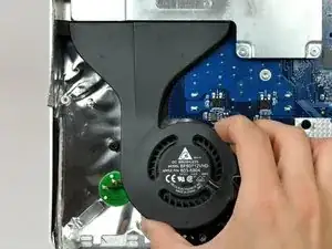
    • Gently lift the CPU fan out of the rear case.

  23. QQ13spBRJx36RZcg
    • Disconnect the following connectors from the logic board by pulling them straight up from their sockets.:

    • Ambient light sensor cable.

    • Power cable.

  24. 6VLS2tLJRiUluvJ2
    • Disconnect the hard drive data cable connector from the logic board by pulling it straight up from its socket.

    • The SATA connector on most iMacs tends to stick in its socket on the logic board. If you are having trouble disconnecting the SATA cable, insert a metal spudger or any other thin tool into the gap between the SATA connector and its socket and twist the spudger's shaft to safely separate the two pieces.

  25. E6dbRy3YgdSfhTuw
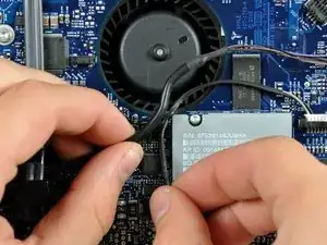
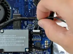
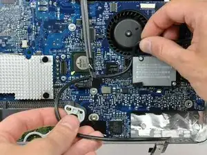
    • De-route the IR sensor cable from behind the AirPort Express card and set it aside.

  26. yxCwfNfKpXBc1XDv
    yxCwfNfKpXBc1XDv
    NxZMr6oNoycl1oWW
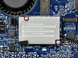
    • Remove two 5 mm T6 Torx screws securing the AirPort/Bluetooth board to the logic board.

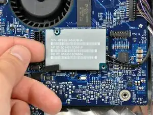
    • Lift the AirPort/Bluetooth board up from its left edge to separate it from its socket on the logic board.

    • Lift the AirPort/Bluetooth board from its left edge only. Trying to lift from its right edge may break the connector off the logic board.

  27. APrUnDMPD6kjPnTW
    APrUnDMPD6kjPnTW
    DsCTXqPlDC6FkqYs
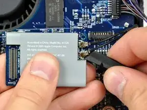
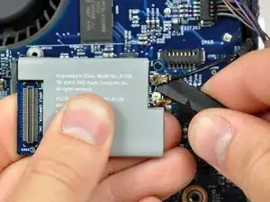
    • Use the flat end of a spudger to pry both antenna cables up off the AirPort/Bluetooth board.

    • This step need not be done. Simply lay the card over the side.

  28. PCPVcpvZRJBCorkQ
    • Disconnect the camera board cable connector from the logic board by pulling it straight away from its socket.

  29. hnjrSfIOLqvQWexA
    • Disconnect the optical drive fan cable connector from the logic board by pulling it straight away from its socket.

  30. MCGosmfnTnnfHVEn
    MCGosmfnTnnfHVEn
    BHPWOP2wduH4MnGH
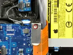
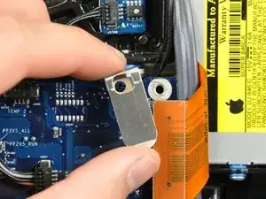
    • Remove the 7 mm T10 Torx screw securing the optical drive flex cable mounting bracket to the logic board.

    • Remove the flex cable mounting bracket.

  31. 2dRZSDHPWCb4eO5C
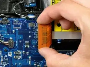
    • Disconnect the optical drive flex cable from the logic board by pulling it straight up from its socket.

  32. eXGhhwLWSJuIs6Ty
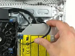
    • De-route the hard drive data cable and tuck it under the optical drive to prevent the cable from interfering with future steps.

  33. faLZQjXNOuJlilOY
    • Disconnect the hard drive fan connector from the logic board by pulling it straight away from its socket.

  34. XMbNwG5uKN6HdjRC
    XMbNwG5uKN6HdjRC
    POXRvvFwMtTevNkA
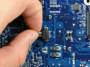
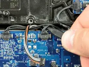
    • Use the tip of a spudger to lift the hard drive and optical drive thermal sensor cables for clearance.

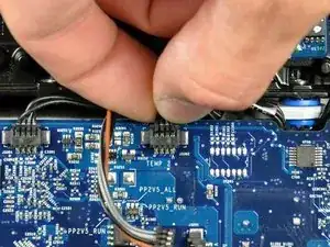
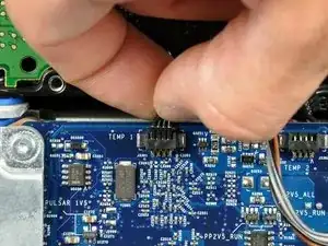
    • Disconnect the optical drive temperature sensor connector from the logic board by pulling it straight away from its socket.

  35. 2X1W4SdTJMGvvdQe
    • Disconnect the hard drive temperature sensor connector from the logic board by pulling it straight away from its socket.

  36. EASXllAUor5OyN2a
    • Remove the following screws securing the logic board to the rear case:

    • Four fine threaded 7 mm T10 Torx screws.

    • Three coarse threaded 7 mm T10 Torx screws.

  37. 5Vpeeq6RNXSZDAtN
    5Vpeeq6RNXSZDAtN
    vi2R1dErrbiyMSRJ
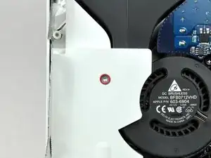
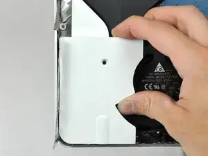
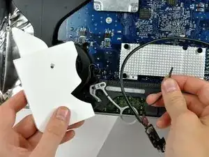
    • Push the two RAM arms protruding from the access door inward and set them on the lower edge of the rear case to prevent them from getting caught when removing the logic board.

  38. SaSwFRHXcAi3pomX
    SaSwFRHXcAi3pomX
    PoZlrhHAojGXnSTi
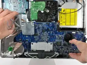
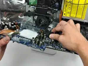
    • Grab the logic board and pull it toward yourself slightly to separate the jacks from the rear case.

    • Rotate the top of the logic board toward yourself slightly to gain access to the DC power cable connector.

    • Do not completely remove the logic board as the DC power cable connector is still connected to the underside of the board.

  39. sPwJOeIKRMi5YdCN
    • While grasping the logic board with one hand, disconnect the DC power cable connector from the logic board by pulling it straight away from its socket.

    • It may be helpful to wiggle the connector while pulling it.

    What is the capacitor list for the board as mine is missing to capacitors

    bear250sxf -

  40. Lvxsk6WFUZZ6FZo5
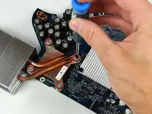
    • Remove the following screws securing the heat sink bracket to the heat sink and logic board:

    • Four 7.8 mm T8 Torx screws.

    • Two 6 mm T8 Torx screws.

  41. eBu1qwyJHHjc5CcZ
    • It may be necessary to hold the Phillips head screw sockets with a Phillips screwdriver while unscrewing the four Torx screws near the corners of the processor.

  42. VOucLrh4BgYiZmAd
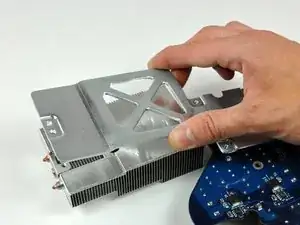
    • Lift the heat sink bracket up off the heat sink and the logic board.

  43. BLYEMbgLxuocVQvJ
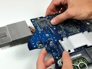
    • Lift the logic board up off the heat sink.

    • If you need to mount the heat sink back onto the logic board, we have a thermal paste guide that makes replacing the thermal compound easy.

Abschluss

To reassemble your device, follow these instructions in reverse order.
Walter Galan

685540 Reputation

0 Kommentare