Einleitung

Use this guide to replace the CPU.

  1. LL6ZKkaC1k3fjQpN
    LL6ZKkaC1k3fjQpN
    JFgfEOMMil6Wa6MI
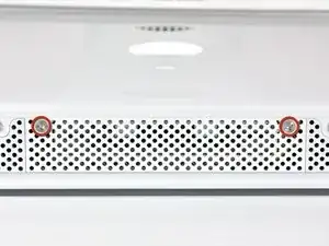
    • Loosen the two Phillips screws securing the access door to your iMac.

    • Both screws remain captive within the access door.

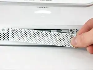
    • Remove the access door.

  2. BMJL1RwW1UZLer3v
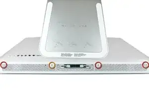
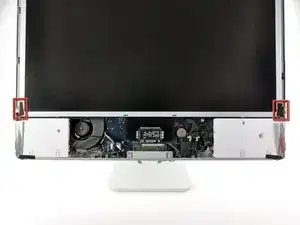
    • Remove the following screws along the lower edge of your iMac:

    • Three 6 mm T8 Torx screws

    • One 8 mm T8 Torx screw

    My iMac had four 6mm T8 Torx screws (so not one 8mm screw)

    floor -

    My late 2006 iMac24 also has only 4, 6mm long T8 screws here.

    JC Gidley -

  3. y5CssgvFJhbaVMYI
    y5CssgvFJhbaVMYI
    drlImZCRxMNH1lyG
    • Lay your iMac stand-side down on a flat surface.

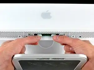
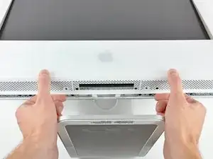
    • To lift the front bezel off the iMac, simultaneously:

    • Use your thumbs to press in the RAM arms and hold the iMac down.

    • Use your index fingers to pull the small bridge of material on the front bezel toward yourself.

    • Pull the front bezel up with your index fingers.

    • Once the small bridge of material has cleared the RAM arms, lift the front bezel by its lower edge just enough to clear the bottom edge of the rear case.

    My iMac did not have the "small bridge of material" mentioned, however the bezel just lifted off easily.

    maccentric -

  4. XF5OJ1jfbYqZF6ih
    XF5OJ1jfbYqZF6ih
    le4ypK11ghkRxDiZ
    GfGw4oMrNjgaLQ6x
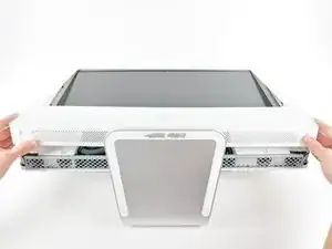
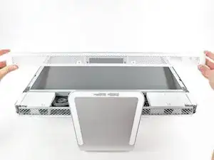
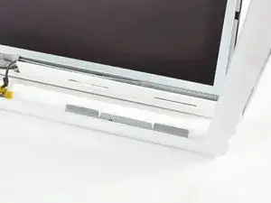
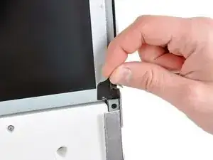
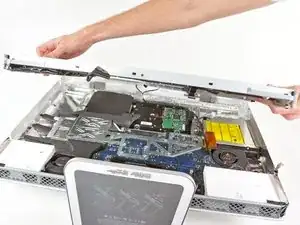
    • Lift the front bezel off the rear case and rotate it away from the bottom edge of the iMac, minding the camera and microphone cables still attached to its upper edge.

    • The third picture shows the top front bezel brackets and their slots cut into the top edge of the iMac's rear case.

    • Do not completely remove the front bezel, as it is still attached by the camera/microphone cables.

  5. GSfpKTBUIFGSkjyO
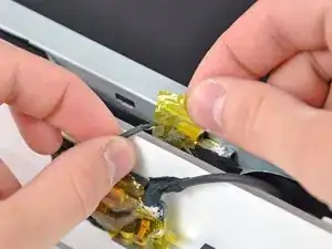
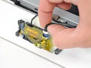
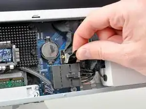
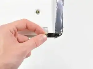
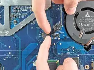
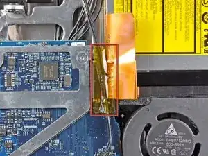
    • If necessary, remove the strip of tape covering the microphone cable connector.

    • The microphone connector is located near the inside of top edge of your iMac.

  6. pRRiD1ryQ2F5BETU
    pRRiD1ryQ2F5BETU
    AQWEuC2Se1pw6ah4
    v3MxvKvMpHYtvEM4
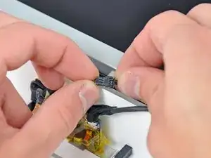
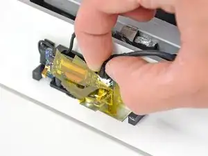
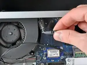
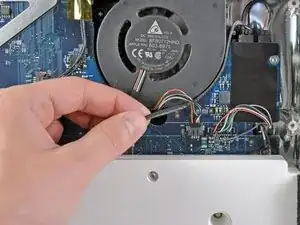
    • Disconnect the microphone cable.

    • Disconnect the camera cable by pulling its connector away from the socket on the camera board.

    • The camera cable connector and socket are delicate and easily bent. Remove with caution.

    I found it easier not to remove the cables connecting camera and microphone, but rather to lean the plastic frame agains a pile of books so that it could rest almost vertical avoiding the need to disconnect those two sensitive cables.

    Stefano C -

    I agree that for a simple, quick battery change, don't risk damaging those delicate wires. Ignore Step 6 and instead of disconnecting the mic and camera wires, keep them in place and just have a friend hold the plastic frame up while you change the battery, or prop it up as mentioned by Stefano C above.

    WT Kwok -

    Make sure you double check the new logic board for the presence of the GPU assembly before installing. I stupidly installed a new board without moving the GPU from the old one first. So i guess you can say this guide worked for me twice. :)

    Trevor Kearsey -

  7. uUBGquKPbFhpIIxR
    uUBGquKPbFhpIIxR
    MdWgVt3W1b2D1t3a
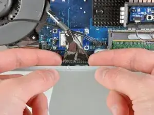
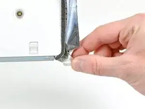
    • Peel the two highlighted EMI shield tabs off the frame of the LCD.

  8. TTTVsccSkGIwqT1W
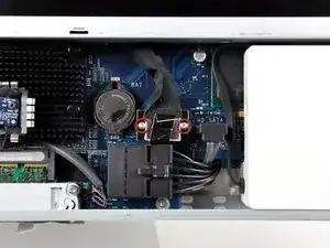
    • Remove the two T6 Torx screws securing the display data cable to the logic board.

    Wait, we need a T6 screwdriver as well?

    I purchased the T8 and T10 from your site as per the parts list above and now am here with an opened iMac on the dining room table unable to continue :/

    Stephen Alianiello -

  9. ex542vRRKQ6cnl55
    • Pull the black plastic tab attached to the display data cable connector to disconnect it from the logic board.

  10. lUe11GfWiaoilYqg
    lUe11GfWiaoilYqg
    AamxNAPKOZH2agn4
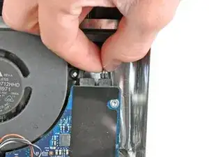
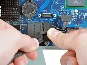
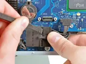
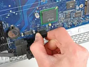
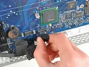
    • Use your fingertips to pull both sides of the wide inverter cable connector out of its socket on the logic board.

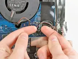
    • De-route the inverter cable from its location next to the CPU fan.

  11. lxXhlNXHYirstgFx
    • Before attempting this step, we recommend laying your iMac stand-side down on a table to avoid the display falling down.

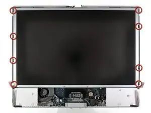
    • Remove the eight T8 Torx screws securing the display assembly to the rear case.

    • It is helpful to use a thin magnetized screwdriver to remove these screws.

    It would be useful to use a torx screw driver with a long, narrow shank… some of these screws are in tight places.

    Joe Liscouski -

    It may also be useful to prop up the back so it is level. This will prevent the screws from falling inside. They can be retrieved once the scene is off.

    John-Francis mergen -

  12. YmtqPI1UP1aEZ3pX
    • Remove the display assembly from the iMac.

  13. BmaTLZiboa5AJYIX
    BmaTLZiboa5AJYIX
    ibuxbBWKkKvpRFxG
    • Peel back the piece of EMI tape connecting the bottom edge of the right speaker to the metal frame of the iMac.

    • Peel the tape away from the lower corner of the right speaker.

  14. shZGjRiEfELfZICl
    shZGjRiEfELfZICl
    AtWSALkj4TDlqqMs
    • De-route the right-hand speaker's cable from between the logic board and the optical drive fan.

    • Disconnect the cable from the logic board.

  15. GUw1jlCKuCfMovmZ
    • Remove the 26 mm T10 Torx screw securing the right speaker to the iMac.

  16. ZMt2h6QFBbwP2a4y
    • Pull the right speaker away from the logic board and remove it from the iMac.

  17. omFFDpQVFVVmUATs
    omFFDpQVFVVmUATs
    RwJDj11PK2waBVUP
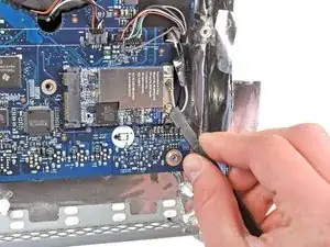
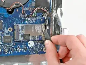
    • Use the flat end of a spudger to pry both antenna connectors off their sockets on the AirPort card.

    • The black antenna attaches closest to the bottom edge of the iMac.

  18. TFVtoYDjYyCOYw1e
    • Use both fingertips to disconnect the camera and microphone cable from its socket on the logic board.

    • Pull the connector perpendicular to the face of the logic board.

  19. HraRomEG1GS4cgKA
    • Pull the optical drive fan connector toward the top edge of the iMac to disconnect it from the logic board.

  20. LCJFAHB6P1kxQCvw
    • Pull the left speaker connector toward the top edge of the iMac to disconnect it from the logic board.

  21. PRQtvPaPt6Zum1Je
    • Pull the optical drive thermal sensor connector toward the right side of the iMac to disconnect it from its socket.

  22. mSH5DbXNZpdgwi5q
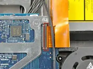
    • If necessary, remove the strip of tape covering the optical drive connector.

  23. h56bSOO2t3HhmKdX
    h56bSOO2t3HhmKdX
    FISH3d3GyKFXwRiy
    LEsfJ5cAlVZOkkNh
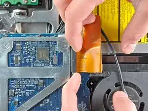
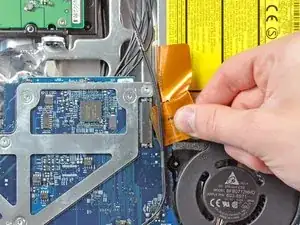
    • Gently pull the cable retainer on the optical drive cable ZIF socket toward the right side of the iMac.

    • The retainer should move about 1 mm and stop. Do not attempt to remove the retainer.

    • Pull the optical drive ribbon cable out of its socket, being careful not to rip it in the process.

  24. 3BTuTQSouCVrtQXs
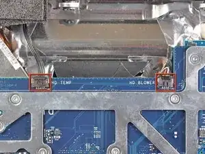
    • Disconnect the hard drive thermal sensor and hard drive fan cables from the logic board by pulling their connectors toward the top edge of the iMac.

  25. S1LPInIopVj2tbAX
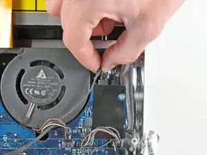
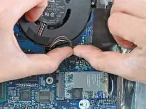
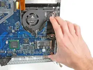
    • Pull the CPU fan connector toward the left edge of the iMac to disconnect it from the logic board.

  26. 2tWHREfDQh4txgNl
    2tWHREfDQh4txgNl
    CFryb5BXHJlBFMZI
    • Disconnect the power button cable from the logic board.

    • Pull its connector perpendicular to the face of the logic board.

  27. EkfOJiPPj3V3eBi6
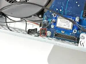
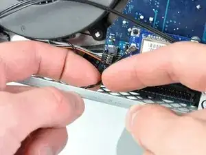
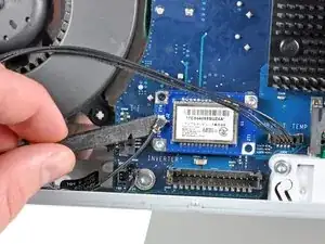
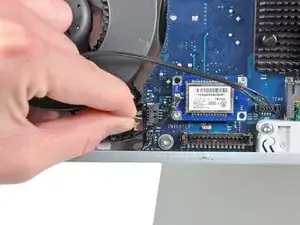
    • Use the flat end of a spudger to pry the single Bluetooth antenna off its socket on the Bluetooth board.

  28. acdifZuqCcRk3C6Z
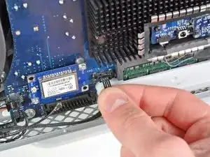
    • Pull the ambient temperature sensor cable perpendicular to the face of the logic board to disconnect it from its socket.

  29. vGsYS1GYhv3VWCKF
    vGsYS1GYhv3VWCKF
    5TTohySEK5iY1ADj
    • Disconnect the DC-In cable from the logic board by pulling its cable toward the right side of the iMac while depressing its locking mechanism.

    • It is helpful to use a spudger and pry from alternating sides of the connector to help "walk" it out of its socket.

  30. dqwRRlZHWttkDnBn
    dqwRRlZHWttkDnBn
    bWL2VXicUHT6UIKm
    4UFwSVcOVJSs4oBi
    • Pull the hard drive SATA data cable perpendicular to the face of the logic board to disconnect it from its socket.

    • To avoid damaging the socket on the logic board, we recommend using a metal spudger to help separate the SATA data cable and its socket.

  31. SColWrjUvOKBJIvb
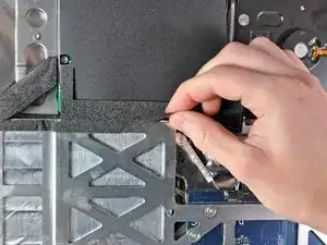
    • Peel the foam tape off the top edge of the heat sink framework.

  32. ZxK5wbIopLpdHYvp
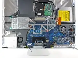
    • Remove the following ten screws:

    • Three 6.6 mm T10 Torx fine thread screws

    • Three 7 mm T10 Torx coarse thread screws

    • Two 9.3 mm T10 Torx coarse thread screws

    • Two 5.3 mm T10 Torx coarse thread screws

  33. aC4rtspwh2cLfhDp
    aC4rtspwh2cLfhDp
    cRh4rGVQMwTsevW2
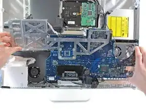
    • Pull the right edge of the logic board slightly away from the rear case to dislodge the rear I/O ports from their bezel.

    • Tilt the top edge of the board away from the rear case and lift the logic board assembly out of the rear case, minding any cables that may get caught.

    • When reinstalling the logic board, it is helpful to use tape to temporarily tuck the cables out of the way until the board is properly seated in the rear case.

    • During reassembly of the logic board, pay attention to the position of the I/O connectors. When the board is back in the case, insert a USB or Thunderbolt cable into one of the connectors to align it perfectly.

  34. otoAlQB316Cgpp6s
    otoAlQB316Cgpp6s
    2votlfrFBonuAKkn
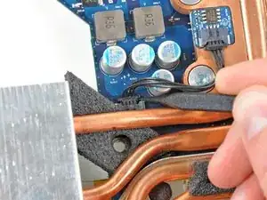
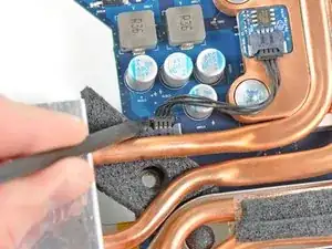
    • Use the tip of a spudger to push the CPU thermal sensor cable connector out of its socket on the logic board.

    • It is helpful to push the connector from alternating sides to "walk" it out of its socket.

  35. NC6vPJcaoileGBl5
    NC6vPJcaoileGBl5
    jHdEhKlSqcxkWyWc
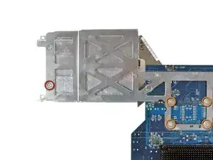
    • Flip the logic board over so it is heat sink side down.

    • Remove the following T10 Torx screws.

    • One short screw near the end of the heat sink.

    • Four screws around the CPU itself.

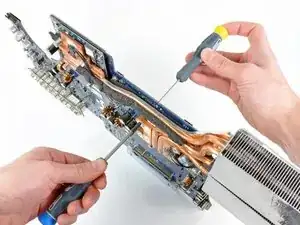
    • It may be necessary to use a #1 Phillips screwdriver to hold the spring loaded screw bosses stationary while you remove the four screws around the CPU.

  36. 3KSW4lT6Yyb1SjEK
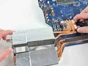
    • Remove the CPU heat sink from the logic board.

    • Before reinstalling the CPU heat sink, be sure to apply a new layer of thermal paste. We have a guide that makes it easy.

  37. rvPkyGAqtSZsktfU
    rvPkyGAqtSZsktfU
    HiMHJxWKpWIQVZIM
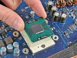
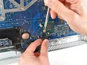
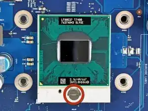
    • Use a small flathead screwdriver to rotate the CPU lock 180 degrees counter-clockwise.

    • Do not try to rotate the lock more than 180 degrees.

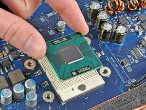
    • Lift the CPU straight up from its socket.

    • When installing a new CPU, be sure the small gold triangle in one corner of the new CPU is in the same position as the old CPU.

    • Before installing the CPU heat sink, be sure to apply a new layer of thermal paste.

Abschluss

To reassemble your device, follow these instructions in reverse order.

Andrew Bookholt

578335 Reputation

Ein Kommentar

Just finished this refurb…. fantastic site and great guide.

The GPU was overheating, and initially, I used SMFan to increase minimum fan speeds and disabled the GPU by following this video

https://www.youtube.com/watch?v=1GDSolVl...

but obviously this limited performance, so I thought , maybe refreshing the thermal paste was help and it has - I decided to do the CPU and the GPU at the same time and the only issue was the antenna terminals broke on the Bluetooth board as I remove the cable - being a bit heavy handed.
A Bluetooth dongle later and this is all fine, the system still runs a little hot, but that’s to be expected and for a 13 year old Mac, its pretty good.

Thanks Folks - really wonderful.
r.holmes -