Einleitung

Wenn ein Joystick an deinem Sony PlayStation 5 DualSense Controller driftet, kannst du ihn mir Hilfe dieser Anleitung tauschen. In diesem Fall ist das Joystickmodul wahrscheinlich abgenutzt und sollte ersetzt werden.

Die Reparatur erfordert Lötkenntnisse auf mittlerem Niveau. Es ist nicht ganz einfach, das Joystickmodul zu entlöten, aber mit etwas Geduld gelingt das schon.

In der Anleitung siehst du, wie das Joystickmodul aufgeschnitten wird, so dass du die Teile mit einem Lötkolben entfernt werden können. Das bisherige Modul wird dabei zerstört. Mit einer Heißluft-Entlötstation wird die Reparatur noch leichter.

Überlege dir, ob du das driftende Modul ein TMR Joystickmodule zum Austausch verwendest, dadurch wird der Fehler dauerhaft beseitigt.

  1. GTfsKVIR12U1WTFu
    GTfsKVIR12U1WTFu
    ePrmMhAFKkXiSkSe
    • Ziehe das Ladekabel ab und schalte deinen Controller aus, bevor du beginnst.

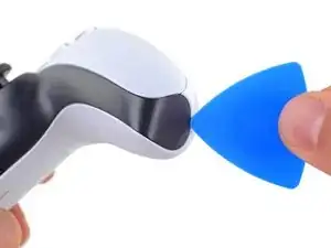
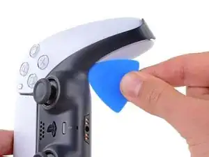
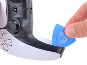
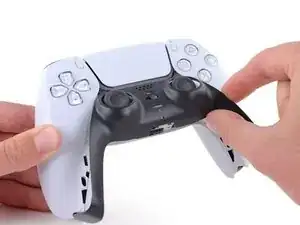
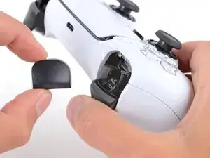
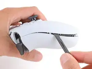
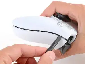
    • Stecke ein Plektrum unter die untere rechte Ecke der Abdeckung, um die Clips zu lösen, mit denen sie befestigt ist.

    What if i accidentally press the playstation button during the repair

    Elias -

    @elias30038 I just hit the circle button and that powered it back off. I think you mostly just need to be careful about it not turning on once you get the electronics exposed at the end.

    Alex B -

  2. Rjcu3KDZixCT6wVc
    Rjcu3KDZixCT6wVc
    PTiPbZOkfusF5DVG
    TciAM3EXVAG6wM3E
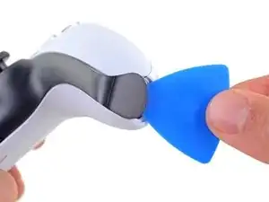
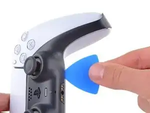
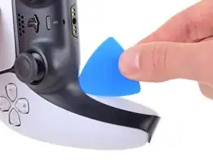
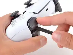
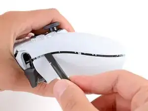
    • Schiebe das Plektrum an der unteren rechten Kante entlang, um die Clips zu lösen, die die Abdeckung festhalten.

  3. d5bIXVWhYD6NuHtO
    d5bIXVWhYD6NuHtO
    VnUyqAC2gatYKPwY
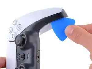
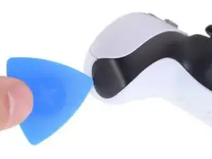
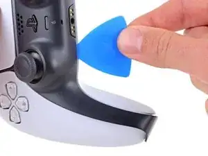
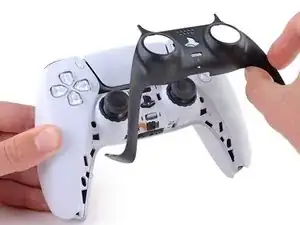
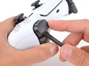
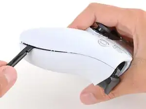
    • Stecke ein Plektrum unter die untere linke Ecke der Abdeckung, um die Clips zu lösen, mit denen sie befestigt ist.

  4. e5VLpDCSJZrCTHZr
    e5VLpDCSJZrCTHZr
    Vmn4XCtKxVVpYw1i
    uGRXgEGmKq2IKNvT
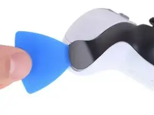
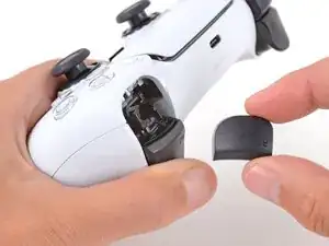
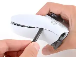
    • Schiebe das Plektrum an der unteren linken Kante entlang, um die Clips zu lösen, die die Abdeckung festhalten.

  5. bQYOnlI5CkoEepwG
    bQYOnlI5CkoEepwG
    FnfBCacKEAvKripH
    MIN3JWiK5kicsBCd
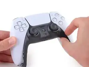
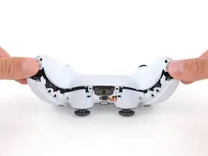
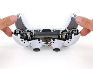
    • Hebe die Abdeckung mit deinen Fingern an der unteren Kante an, um die restlichen Clips zu lösen.

    • Hebe die Abdeckung über die Joysticks, um sie zu entfernen.

  6. bkMg2Eo6RVJBRwJE
    bkMg2Eo6RVJBRwJE
    FkNGiCeBPPV6tcfk
    Bsl3YMbrH2Q5nOTU
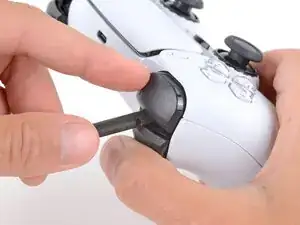
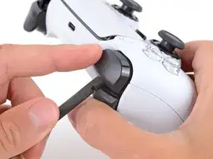
    • Fasse den Kontroller mit einer Hand und halte den linken Auslöser mit dem Daumen gedrückt.

    • Setze das flache Ende des Spudgers mit der anderen Hand zwischen die L1 und L2 Tasten ein.

    • Heble die L1 Taste mit dem Spudger behutsam vom Kontroller weg, halte dabei den Finger darüber, damit die Taste nicht davonspringen kann.

    Tried prying from the front of the buttons as pictured and my spudger broke off in the gap. A video I watched showed them being pried off from the back (between the R1/R2 and L1/L2 buttons) which seemed much easier.

    Lora Singleton -

    Agree with Lora's comment above. I was able to use an old credit card to take L1/R1 out this way. I pressed down the L2/R2 button to create space to work in, then came in from between L1/L2 and R1/R2. It's easy to pop one of the outer corners first then you can work the credit card around the top and the rest falls out.

    darkstar448 -

    Man, if I'd just read the thumb part...

    caldugen -

    erst überlegen, und dann....

    Oliver -

  7. mNyBpuCPfU2EZivG
    mNyBpuCPfU2EZivG
    JR4mA33SaJbxJtnh
    mluWrqHlwtNLXBHV
    • Wiederhole den vorherigen Schritt für die R1 Taste.

    to save a few bucks, the L1 and R1 buttons can be removed without the use of the spudger tool by using any thin prying tool and just pry the buttons from the bottom instead of the top

    Alan Peng -

    What I didn't see addressed anywhere (here or in other similar articles) is that replacement R1 / L1 buttons can be differ enough to be un-usable depending on which model your ps5 controller is. The ones I ordered don't fit and now I can't find a way to be sure I get the right ones because few know there's even a difference.

    Walt Mather -

    Did you already figured it out? The version the we need yo use?, We are in the same situation here.

    Gerald Ross Rodriguez -

    Tried prying from the front of the buttons as pictured and my spudger broke off in the gap. A video I watched showed them being pried off from the back (between the R1/R2 and L1/L2 buttons) which seemed much easier.

    Lora Singleton -

  8. RTMdTIsvXlDMMLCE
    RTMdTIsvXlDMMLCE
    3xBGQ3AXp52YbXKM
    • Entferne die beiden 6,4 mm Kreuzschlitzschrauben, die die unteren Enden des Gehäuseunterteils fixieren.

  9. rkti2BnvDAh1TREh
    rkti2BnvDAh1TREh
    YyonYJBpMSo32LBL
    • Entferne die beiden 6,4 mm Kreuzschlitzschrauben hinter den L1 und R1 Tasten.

  10. Xc1l4aJ6u6BGp5RP
    Xc1l4aJ6u6BGp5RP
    LjguKaIMMeWPUAgo
    dItxRHYBJkALcAlp
    • Sei sehr vorsichtig beim Ablösen der Clips an der Gehäuserückseite - sie sind sehr empfindlich und gehen leicht kaputt.

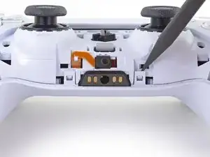
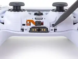
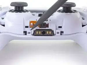
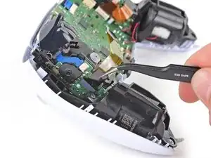
    • Löse die beiden Clips links und rechts von der Kopfhörerbuchse mit der Spitze des Spudgers.

  11. PlREPIyu3XjYsEEV
    PlREPIyu3XjYsEEV
    T3E2bKLKMWY3pBhh
    yS3JuXYoXheuDeji
    • Die Gehäuserückseite ist an der linken und rechten Seitenkante mit fest sitzenden Kunststoffclips befestigt.

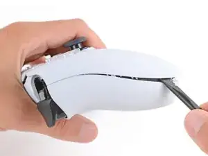
    • Setze einen Spudger mit dem flachen Ende zwischen das vordere und hintere Gehäuseteil ziemlich unten an der linken Kante.

    • Schiebe den Spudger an der linken Kante entlang und drücke die Gehäuseteile auseinander, um die Clips zu lösen.

    Be careful when prying into the shell because i damaged mine prying it open too forcefully

    Elias -

    there is two screws if its too hard to open it up at the end of it

    samaka -

  12. pBh4N2vrrxvn5CrT
    pBh4N2vrrxvn5CrT
    DxPhIgUVCJrqPf3d
    urUJIpGpfAOnvYlh
    • Löse auf gleiche Weise die Clips an der rechten Kante.

  13. 1oJ2lGLAwEZABd4K
    1oJ2lGLAwEZABd4K
    XcdcRmPl2iBBD1Y3
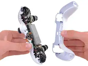
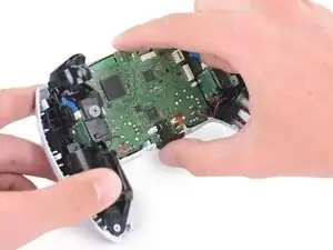
    • Lege den Kontroller mit der Rückseite nach oben, so dass die Joysticks auf der Arbeitsfläche liegen.

    • Halte den Kontroller mit den Fingern nach unten und hebe die Gehäuserückseite mit den Daumen nach oben ab.

  14. eRemnBXLmRUfuESX
    • Entferne das Gehäuseunterteil.

    There are four more clips/hooks hidden in the seams along the outer sides of the handles. If you pull open the controller as shown in this step, then you will shear off the two tiny clips which are right next to the R1 and L1 buttons.

    Therefore, you should first release those clips by prying the seams open sideways.

    I noticed this with the updated design of the controller, not sure whether the hooks are present on the first version.

    The hooks are not critical for the integrity of the controller as the two halves are held together by the screws hidden under the buttons. The damage does show that the controller has been taken apart.

    Nick -

    Thought I'd clarify: The clips next to the L1 and R1 are on the outer side from the L1 and R1 buttons, I'd suggest zooming in on the picture to see them. They're quite easy to break, but also easy to remove using the plastic spudger along the seam, bending the bottom cover outwards

    Franz Rolfsvaag -

    I am still strugling to find the clips. Could someone point them out in the image with a screen shot or something like that.

    aGingerThing -

    I keep getting stuck at this step too with the new DualSense CFI-ZCT1WA revision. The top and bottom shells seem like they are fused together next to L1/R1 but I can't seem to be able to find where these hidden clips are located. My controller is still in warranty so I don't want to break them in case I can't fix my issue.

    but also easy to remove using the plastic spudger along the seam, bending the bottom cover outwards

    I tried this but it seems that the you need a lot of force and I ended up bending the tip of my spudger. Are you sure it's not the top cover that you need to pry away? The bottom cover has a ridge to make sure it's under the top cover so it's not easy to bend outwards.

    @samomio I think there needs to be a step added for these new clips.

    robplease -

    Ok, not seeing a lot of motion on this request, so I've uploaded photos of the hooks to imgur.

    Here ya go: https://imgur.io/a/7NWmQi5

    Sean Murphy -

    Life save Sean. Appreciate the image.

    Vili -

    This guide really needs an update on this. I had a really hard time getting the forward clips to release even after referring to the comments above. Pretty sure I broke them in the end. No big deal but would be great if the iFixit experts could work out a good method for releasing them.

    Marcus Harvey -

    I finally figure it out!!

    The hidden clip is very tricky but once you understand how it works it is easy to remove.

    Use Sean's picture: https://imgur.io/a/7NWmQi5

    What sean is showing, is actually the bottom shell of the seam.

    To disassemble

    1. Use the flat side of the spudger, pry the bottom seam OUTWARDS near the R1/L1 button hole.

    2. (most important) While prying the bottom shell seam outwards, push your thumb on the upper shell and push outward as well (you can do this by applying pressure from the removed R1/L1 button hole towards the seam. And then it will disassemble automatically

    And that's it!

    Penn -

    updated instruction:

    I finally figure it out!!

    The hidden clip is very tricky but once you understand how it works it is easy to remove.

    Use Sean's picture: https://imgur.io/a/7NWmQi5

    What sean is showing, is actually the bottom shell of the seam.

    To disassemble

    1. Use the flat side of the spudger, pry the bottom seam OUTWARDS near the R1/L1 button hole.

    2. (most important) While prying the bottom shell seam outwards, hold your thumb on the upper shell as anchor and then use your other finger to pry the bottom edge of the controller up away from the shell. If you are doing the first step, then don't worry about breaking the clip, just force it open. And then it will disassemble automatically

    And that's it!

    Penn -

    Yes! Thanks a bunch Penn. That did the trick! Much appreciated

    Sean -

    I managed to do it just by pulling harder than what I was already doing. And I don't think I broke anything. So, for me at least, the technique described in this guide worked.

    Riedweg Guillaume -

    The video linked below clearly shows how to open the controllers with the extra clips near the L1/R1 areas.

    See a video here by How To X on YouTube... https://youtu.be/djIvRoclr_E?si=dKFpQCZe...

    Jason Z -

    I really struggled with releasing the rest of the back panel (close to the shoulder buttons.) What finally seemed to do the trick for me, was doing both sides at once with upward turning motion of the back panel with the shoulder buttons approximately at the axis. Trying to release just one side and then the other felt impossible without potentially breaking the case.

    dborba -

    This was what did it for me

    Matthew Williamson -

    这里没有写

    注意拆后盖的时候的用力方向

    l1 和 r1 附近有卡扣,用力方向不对会破坏这两个卡扣,我的已经破掉了。

    e而且这个卡扣附近有螺丝锁定,我怀疑是不是故意被设计来检测手柄有没有被拆开过。

    Mussa Ding -

  15. y641KJMcsYBEboOS
    y641KJMcsYBEboOS
    E6YeMuX4VK4rKsAg
    • Trenne das Akkukabel mit einer Pinzette oder deinen Fingern vom Motherboard.

    • Ziehe beim Abtrennen nicht an den Kabeln, sondern an den Steckern.

    Tweezers aren't gonna grip that the way you need.

    Leif DeWolf -

    For those having trouble using tweezers to pull out the connector, you can grab below the lip of the connector and use the controller as a lever to pull it up as seen here DualSense Kontroller v2 Akku tauschen

    This little trick helped me so much and I believe it should be shown on this guide as well.

    Ezra Worthington -

    Tweezers is too weak for this. I use my finger nails after removing the battery from the slot, straighten the cable lines and slowly wiggle it out.

    Penn -

    you’re the absolute goat

    zane061 -

    Tipp: I use isopropyl alcohol if a plug will not disconect. Just a few drops into the plug and it will get lose.

    Nikolas Weiler -

  16. ONKEXniLxYyiAMwP
    ONKEXniLxYyiAMwP
    OU1aauS5WB3RXnNv
    • Hebe den Akku gerade aus der Halterung.

    Wäre schön ein Link mit dem Werkzeug, das man braucht - Danke!

    Sam Hawkins -

    ALWAYS double check the polarity of the plug on your replacement battery! Compare it to your old battery. Errors can happen, particularly with 3rd party replacement batteries.

    HelloMiakoda -

  17. sVsceB4EJJN4igAW
    sVsceB4EJJN4igAW
    LWv3kRdOD3MyIOxA
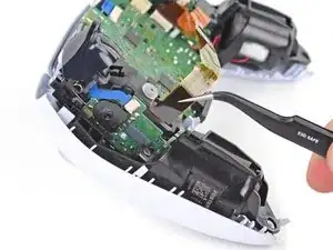
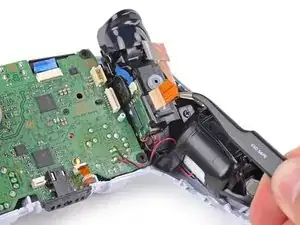
    • Ziehe das Kabel des unteren Mikrofons mit einer Pinzette oder deinen Fingern aus dem Anschluss auf dem Motherboard.

    These ribbon cables have small tabs on either side you can use to help pull out the cable. You can slightly pull up, alternating between the two sides, to slowly wiggle the connector out.

    Tran Anh Nguyen -

    Might be a rookie mistake, but DO NOT REMOVE THE WHITE BRACKETS, only the ribbon! If you do, you’ll have an awful time putting it back and will most likely mess it up. Yes I did.

    Joris D -

    I tried to use metal tweezers to pull this out and absolutely shredded the ribbon in the process. It's just a microphone so I wouldn't expect it to matter but now none of the games get any input from the controller even though the controller works fine in the home menu 🥲

    Probably just use your fingers if you have the dexterity for it.

    Grey -

    As others have said, try to only remove the ribbon and not the white connector. I'd advise holding down the white connector with something (perhaps your prying tool or finger) as you pull the ribbon out gently with the tweezers.

    Best to avoid pulling out the white connector if possible - but its not the end of the world if you do accidentally pull it out, as I did. You can put the connector back in but you need to be very precise with the alignment over the 6 pins it connects to on the circuit board. I had to use a magnifying glass and it took me a few attempts.

    Fruke -

    I didn't read the comments until it was too late and I've ended broken all the pins trying to put it back. There should be some disclaimer in here because I've just lost the mic input trying to fix a joystick and there's no getting that back. And in the most stupid way.

    Jordi -

    I accidentally removed the white bracket but all the pins looked straight so i just put the bracket back on

    Elias -

    Same thing happened to me. Please add a warning to NOT remove the white connector. I lost two of the pin sets and I’m accepting the fact I’ll never be using the mic again on this controller.

    Dale Harris -

    Leave the microphone attached to the battery tray, detach the ribbon cable, and lift it out as one unit.

    Robert Anthony -

  18. 1sbxrgZE212ACjfZ
    1sbxrgZE212ACjfZ
    WHQWFFeIquSFVPFh
    • Entferne die 6,4 mm Kreuzschlitzschraube, die die Halterung für den Akku fixiert.

  19. MVqtcLTeGaGZO6Lw
    MVqtcLTeGaGZO6Lw
    eaAKIGVAOolyyZ5Q
    • Hebe die Akkuhalterung vom Motherboard.

    Black and red wires fit neatly under the lower left and lower right arms of the battery bracket, to avoid potential damage when reconnecting the rear case.

    Seomhnasaigh B -

    This needs to be noted. Thanks!

    Nick Gatti -

    Good call on this one for sure. You DO NOT want to crush those cables with the battery bracket.

    Jack Albertelli -

  20. vysKPAMs3LmOUmiY
    vysKPAMs3LmOUmiY
    QLbCmreHvepGMkOB
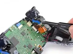
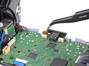
    • Löse das Kabel der rechten Tasteneinheit, indem du es mit einer Pinzette oder deinen Fingern aus dem Anschluss auf dem Motherboard ziehst.

    • Entferne das Flachbandkabel noch nicht ganz.

    If your cables are blue and in a different position, don't sweat. It's all good. Just do the same as they do and if you feel it is necessary, label with a sharpie left and right on each cable. A simple L and R works for this case

    Qbert 2030 -

    My controller looks different than in the photo the connector tips are blue are the repair procedures same even if my controller is different. Please help this is my first time repairing electronics

    Elias -

    I noticed the different connectors i have repaired bdm 010, bdm 020 and bdm 040 controllers all the models seem to be different to identify your controller’s bdm use a website called https://exr.gg and plug in your controller with an usb cable

    Elias -

  21. BgY2EFxlGP1qu1JF
    BgY2EFxlGP1qu1JF
    UEM6rxfOxTPtriIO
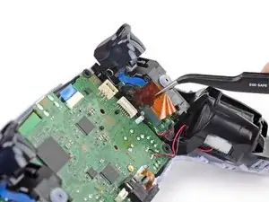
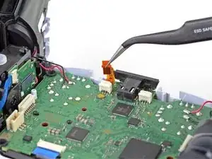
    • Greife die Lasche des Kabels an der rechten Tasteneinheit mit einer Pinzette oder deinen Fingern und trenne es von der Tasteneinheit.

    • Entferne das Kabel.

    Depending on the revision of your controller, these ribbon cables may be slim and white and if you remove it completely, you might have to remove and tear down the trigger assembly to get the ribbon cable back in.

    Robert Borrero -

    maybe I'm missing something but in this case it doesn't seem to me like these cables need to be outright removed.

    TheHooligan95 -

    Agreed… there is no need to remove from the trigger itself. Just the motherboard. This needs to be fixed.

    Jack Albertelli -

  22. DNCfVqeUwEBVL5vx
    DNCfVqeUwEBVL5vx
    fkYnkZICbnGNYmlL
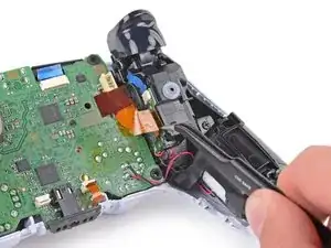
    • Löse das Kabel der linken Tasteneinheit, indem du es mit einer Pinzette oder deinen Fingern aus dem Anschluss auf dem Motherboard ziehst.

    • Entferne das Flachbandkabel noch nicht ganz.

  23. 1mamEpkmIUfdBkY2
    1mamEpkmIUfdBkY2
    rRFlFNnP2UoIL3ad
    • Greife die Lasche des Kabels an der linken Tasteneinheit mit einer Pinzette oder deinen Fingern und trenne es von der Tasteneinheit.

    • Entferne das Kabel.

    Be careful, the cable is extremely fragile and i wouldn’t use sharp tweezers to unplug it. I learned that the hard way.

    Egor Shmoylov -

    Me too, is that ribbon cable for sale separately by chance? Lol

    Brn2bndair -

  24. pG1fDWglZbP4iL5N
    pG1fDWglZbP4iL5N
    Hp2VFaarDEOKof3P
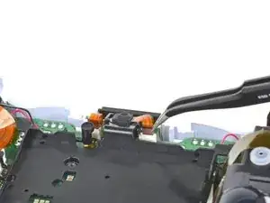
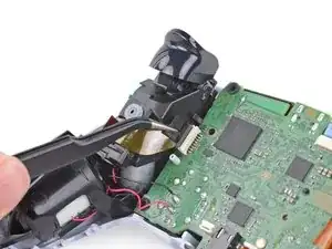
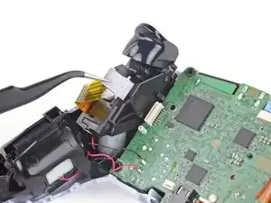
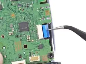
    • Ziehe das Kabel des oberen Mikrofons mit einer Pinzette oder deinen Fingern aus dem Anschluss auf dem Motherboard.

    what is the white thing soldered to the motherboard called where the mic ribbon cable plugs and where can i find the part?

    Abhi K -

    @abhik13943 did you ever find this part?

    DaMej2895 -

    unfortunately, no. i'm just using my controller without a mic.

    Abhi K -

  25. HcN3WXjBdpXKafMs
    HcN3WXjBdpXKafMs
    eYVKcU6OsxOKcb1S
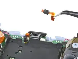
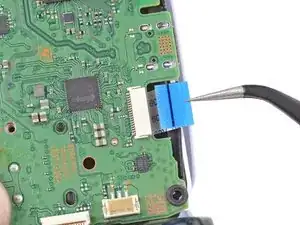
    • Ziehe das Kabel des Touchpads mit einer Pinzette oder deinen Fingern aus dem Anschluss auf dem Motherboard.

    This ribbon cable can be removed more easily by gently lifting the board to create a small gap, then using that space to pull the cable from the bottom.

    Robert Anthony -

  26. GqsGfFE6VFsbGvhX
    GqsGfFE6VFsbGvhX
    4IvPQ2aVt4oyB4MS
    iI24ALvZsMEZZMRI
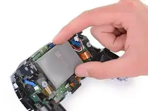
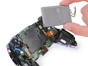
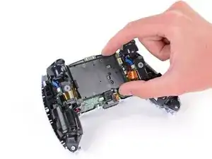
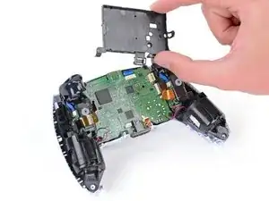
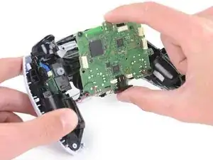
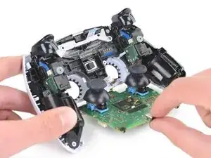
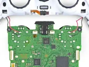
    • Führe die Joysticks vorsichtig durch die Gehäusevorderseite und hebe das Motherboard heraus.

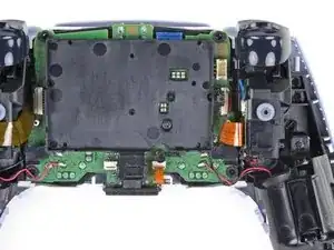
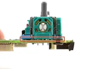
    • Die Platine wird von zwei Clips nach unten gehalten, einer zwischen ihr selbst und der rechten Triggereinheit und einer zwischen der Platine selbst und der linken Triggereinheit. Drücke behutsam auf die beiden Clips, um die Platine zu lösen.

    • Entferne das Motherboard noch nicht vollständig. Vier angelötete Kabel verbinden das Motherboard mit den Vibrationsmotoren.

    Pushing on the joysticks makes this much easier.

    zidek22 -

    My motherboard wouldn't just lift right out. So I noticed there's also a pair of barely visible small black clips, one on each side of the motherboard, holding it down. One is right beside the battery connector and the other's directly across on the opposite side of the motherboard right beside the ribbon cable connector.

    Jason Mulholland -

    Such a good observation!

    zidek22 -

    That helped a lot. If you can push those tabs it comes out a lot easier. I used my tweezers to push the left one and then as others had said pushing on the joysticks from the front of the controller makes it much easier.

    Fruke -

    Just push on the sticks. Pops out like a charm, zero effort.

    Italian Retro Guy -

    Try to leave the controller on its front when you pop out the board, otherwise the speaker can fall out like mine did.

    James Hartman -

  27. cIxQeXAmdD53yC1w
    cIxQeXAmdD53yC1w
    JySpNaUyvfCM6PPx
    BhZHddTHDjZURSEb
    • Bei den nächsten Schritten musst du löten und entlöten. Kenntnisse zum Löten vermittelt dir unsere Lötanleitung, wenn du schon löten kannst, findest du dort immer noch hilfreiche Tricks und Tipps.

    • Drehe die Platine und den Kontroller um.

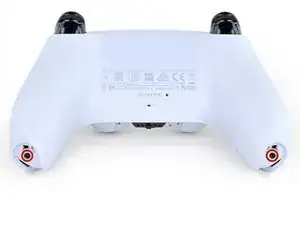
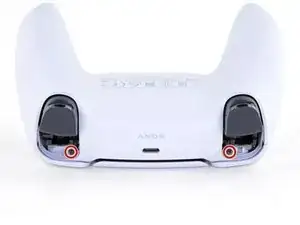
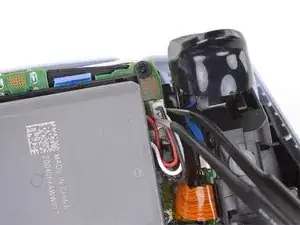
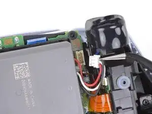
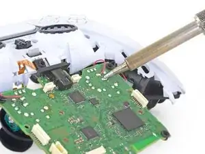
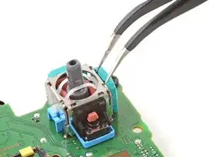
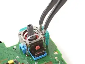
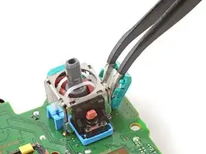
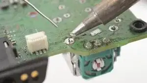
    • Entlöte die Kabel der Vibrationsmotoren mit Hilfe eines Lötkolbens von der Hauptplatine:

    • Zwei rote Kabel

    • Zwei schwarze Kabel

    • Denke beim Zusammenbau daran, die Kabel wieder an der gleichen Position zu verlöten. Die roten Kabel gehören direkt an den Rand neben den Rs auf der Hauptplatine.

    but how do I solder them back and at what temperature. I’m a kid that’s why i’m asking. Also should i wear gloves . My controllers black wire disconnected so this is why i’m asking and yes i know how to do it and i will be supervised. I watch I Tronics fix’s videos so i’ma a big fan of him and all i know about this kind of stuff is from him.

    ps_fan_1 -

    The temperature will depend on the solder and tip you are using. Start at 180°C (360°F) and increase temperature as needed.

    To solder the wire back on:

    1. Place the end of the wire on the solder pad on the motherboard. Use something to hold it in place while you work, like helping hands.

    2. Heat up your soldering iron and touch the tip to the solder pad for 15-30 seconds to get it hot.

    3. With the soldering iron and wire touching the pad, use the tip of your soldering iron to melt just enough solder to cover the wire and pad. Remove the solder and soldering iron tip as soon as enough solder melts onto the pad.

    Wearing gloves and safety glasses is a good idea if you’re new to soldering, and practice on something else first. Read our soldering guide before you start too.

    Sam Omiotek -

    What if I want to leave the vibration motors out? Is there anything special that has ti=o be done?

    Super Korean -

    In addition to the 2 red and 2 black wires, my controllers also have 2 yellows and 2 greens. So 8 wires total. I'm going to remove all of then and then install in reverse order. Wish me luck!

    Dallas Hall -

    Dieser Schritt wirt einfach unmöglich ich habe für 2 Stunden damit vergeblich gekämpft auch nur eines der Kabel zu lösen. Und das mit meinem Lötkolben auf 450°C. Wie es mit "optimierten" ent-löt tools aussieht konnte ich nicht testen, da ich es vermutlich für immer aufgeben werde Dinge die Löterfahrung benötigen zu repairieren.

    Kurz gesagt, versucht diese Reparatur garnicht erst, wenn ihr nicht SEHR viel erfahrung habt. Kauft euch lieber einen pre-gemoddeten Kontroller (was ich jetzt vermutlich machen werde).

    Luca -

    Can a copy of this guide be included for the newer models (V5 controllers don't have this guide linked). Although it may be easier to keep this guide for all models and add a note to desolder the additional two wires for newer models of the controller. Not much has changed across these models and the guide applies for the most part.

    Thanks.

    JohnP. -

  28. L6peLyuAkiXpNg6V
    • Trenne den Controller von der Hauptplatine.

  29. rZA5GsZg1CKGGrh2
    rZA5GsZg1CKGGrh2
    tjVEjLIkjKRpKVI1
    xHpjZVCWQxO1QvmK
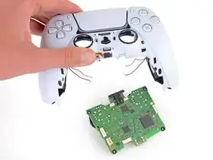
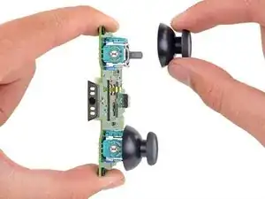
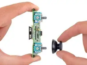
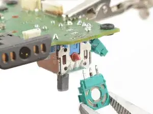
    • Ziehe die Joystick-Abdeckungen gerade von den Joystick-Baugruppen ab.

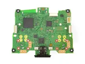
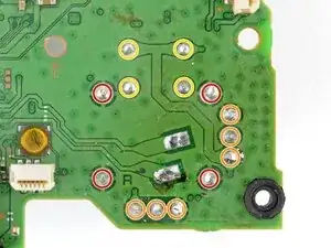
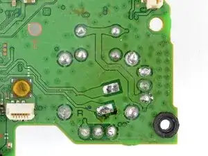
    • Nun bleibt nur noch das Mainboard übrig.
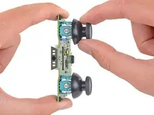
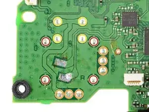
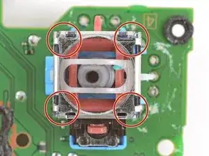
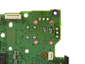
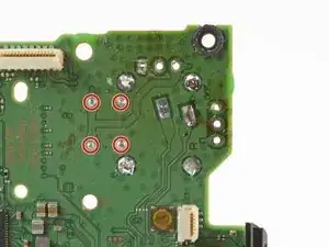
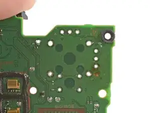
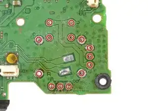
  30. jysPsArbeK1OSTem
    jysPsArbeK1OSTem
    UFoAm4LvMsReew4R
    lY13uTcf4NSRwCS1
    • Es kann sein, dass deine Platine etwas anders aussieht, aber grundsätzlich kannst du der Anleitung folgen.

    • Jedes Joystickmodul ist mit vierzehn Lötstellen befestigt:

    • Vier Verankerungen

    • Sechs Lötstellen für die beiden Potentiometer

    • Vier Lötstellen für die Druckschalter

    • In den weiteren Schritten wird gezeigt, wie das linke Modul ersetzt wird (wenn der Controller zu dir zeigt). Das rechte Modul wird auf gleiche Weise ausgetauscht.

  31. Vo5G51dhFBGPCeiP
    Vo5G51dhFBGPCeiP
    RiNNCK3Gn2dwKxIi
    n5FfXV6cgv6bi4dD
    • An jedem Joystickmodul gibt es zwei Potentiometer, das sind die farbigen quadratischen Blöcke an den beiden Seiten des Joysticks.

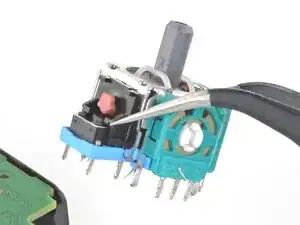
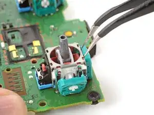
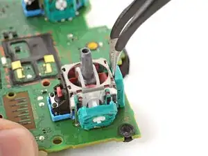
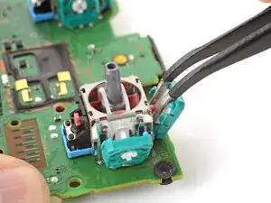
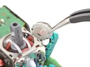
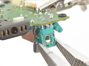
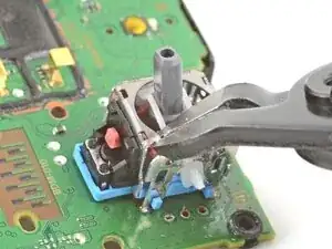
    • Setze die Spitzen einer gewinkelten Pinzette zwischen die Oberkante eines der Potentiometer und dem Rahmen des Joysticks ein.

    • Kippe die Pinzette nach unten, damit sich die Oberkante des Potentiometers vom Rahmen des Joysticks wegbiegt.

  32. feEmZGpjGa4S3YUD
    feEmZGpjGa4S3YUD
    fUcwrdvEQmOdBnV4
    BeRwRCLHYbyvPJhb
    • Wiederhole das Verfahren am zweiten Potentiometer.

  33. DVJHiv6NGVaoqdlZ
    DVJHiv6NGVaoqdlZ
    aaaGDmOCRraXEAjc
    • Entferne den Schleifer aus jedem Potentiometer mit einer Pinzette.

  34. gGSILbYX3oEtoqhF
    • Fixiere die Hauptplatine mit einer dritten Hand oder einem ähnlichen Werkzeug so, dass die Lötstellen der Potentiometer nach oben zeigen.

    • Schütze die SMD-Bauteile auf der Platine z.B. mit Clips

  35. ZWvPTPSOLYOmt3F1
    • Trage etwas Flussmittel auf die drei Lötstellen von einem der Potentiometer auf.

    • Das Flussmittel verbessert die Fließeigenschaften des Lötzinns beim Schmelzen, so gelingt die Arbeit besser. Wenn das Lötzinn klumpt oder klebt, trage mehr Flussmittel auf.

  36. htnRSvDDpH5GCKPu
    • Stelle den Lötkolben auf 375 – 400°C ein.

    • Hier wurde bleifreies Lötzinn verwendet, es erfordert eine höhere Temperatur als solches mit Blei.

  37. Weitere Hinweise zum Entlöten von durchgesteckten Bauteilen findest du in unserer <a href="../../Anleitung/Wie%2Bman%2BL%C3%B6tverbindungen%2Bherstellt%2Bund%2Bentl%C3%B6tet/750">Lötanleitung</a>.
    • Weitere Hinweise zum Entlöten von durchgesteckten Bauteilen findest du in unserer Lötanleitung.

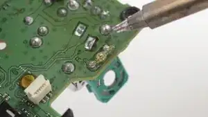
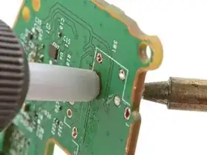
    • Drücke die Lötspitze an eine Lötstelle des Potentiometers, um sie zu erhitzen.

    • Halte die Lötspitze nicht länger als 15 Sekunden an die Lötstelle, das Lötauge könnte kaputt gehen.

    • Wenn das Lötzinn nicht schmilzt, dann gibt etwas bleihaltiges Lötzinn auf die Lötspitze und versuche es nochmals. Das verbleibe Lötzinn sorgt für eine bessere Wärmeübertragung durch eine niedrigere Schmelztemperatur.

    • Wenn das Lötzinn flüssig ist, dann sauge es mit einer Entlötsaugpumpe ab.

    • Führe dieses Verfahren mehrfach an der gleichen Lötstelle durch, um möglichst viel vom Lötzinn zu entfernen. Erhitze die Lötstelle nicht länger als 15 Sekunden auf einmal.

  38. PVCY55TlUZn2Cuxj
    • Entlöte auf gleiche Weise die anderen beiden Lötstellen des Potentiometers.

  39. Z4PCdYMtODV65SMN
    • Diese Schritte zeigen, wie das restliche Lötzinn mit Entlötlitze entfernt wird. Wenn das Potentiometer bereits frei ist, überspringe diesen Schritt.

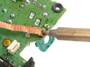
    • Trage etwas Flussmittel auf die Lötstelle auf.

    • Lege ein Stück sauberer Entlötlitze auf die Lötstelle.

    • Drücke die heiße Lötspitze auf die Litze. Das restliche Lötzinn schmilzt und wird von der Litze aufgesaugt.

    • Wiederhole diesen Vorgang an den anderen beiden Lötstellen.

  40. 21XwjYjmL3XMToNv
    21XwjYjmL3XMToNv
    NVdBX2Xp3LG2qWku
    sL6OilUIXUlg3Wbk
    • Ziehe das Potentiometer mit einer Pinzette oder einer Spitzzange vorsichtig von der Platine ab.

    • Wenn sich das Potentiometer nicht leicht lösen lässt, dann wiederhole nochmals die letzten drei Schritte, um die letzten Reste des Lötzinns zu entfernen.

    • Du kannst auch versuchen, jede einzelne Lötstelle zu erhitzen und dabei am Potentiometer zu wackeln und herauszuziehen. Am besten gelingt das, wenn dir eine zweite Person dabei hilft.

  41. SOqKNLnLLlweGKeU
    SOqKNLnLLlweGKeU
    fsG6lcKo4MNbPaqq
    fCbFR1ZT61c6slqo
    • Entferne auf gleiche Weise das zweite Potentiometer.

  42. TltL5ZXcAN2kL3MC
    TltL5ZXcAN2kL3MC
    UHtCiVN2EqN2Qiti
    uLtaQnZnqnpx3Njr
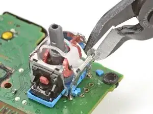
    • Die nächsten Schritte zeigen wie der Rahmen des Joysticks auseinander gebrochen wird und entfernt wird.

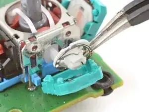
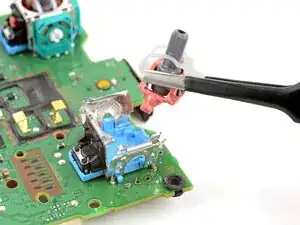
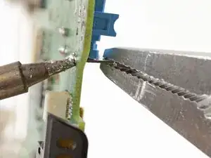
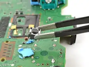
    • Schneide die oberen Ecken des Potentiometers mit einem Seitenschneider vom Rahmen ab. .

    • Sei vorsichtig und verletze dich nicht an den scharfen Kanten. Biege scharfe Kanten mit einer Zange nach unten.

  43. EIDSS6TIhZYv4dEc
    • Biege den Metallrahmen mit einer Zange vom Modul nach außen weg.

  44. fEjrVsAViUZB4MsW
    fEjrVsAViUZB4MsW
    igFRMtQJJICVPZIU
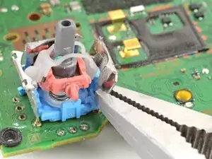
    • Entferne die Kunststoffteile aus dem Inneren des Joystickmoduls.

    • Entferne alle lösen Teile vom Modul.

  45. S1FqfrsDyLs3KKXd
    S1FqfrsDyLs3KKXd
    gWFUQT3QyLu2ECk6
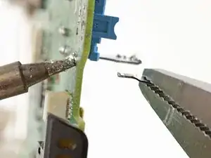
    • Schneide die Metallwände des Rahmens oben mit einem Seitenschneider auf, so dass sie in zwei Teile zerlegt werden.

  46. wZRomEZD2HswrFBp
    wZRomEZD2HswrFBp
    2AKJlRUnFhLTUcj3
    gthhHOZeLQwDJOVp
    • Fixiere die Hauptplatine so, dass die Lötstellen oben liegen.

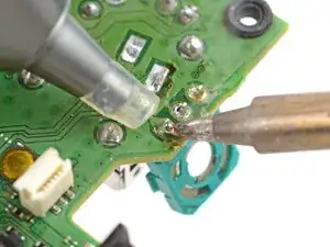
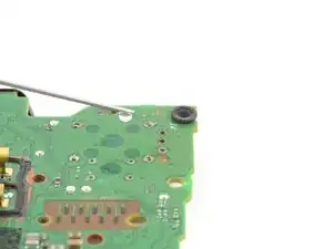
    • Erwärme eine der Lötstellen der Verankerung mit der Lötspitze.

    • Wenn das Lötzinn geschmolzen ist, ziehe die Verankerung mit einer Spitzzange aus ihrem Durchsteckloch heraus.

    • Wenn das Lötzinn nicht schmilzt, dann bringe etwas bleihaltiges Lötzinn auf die Lötspitze versuche es nochmals.

    • Entferne in gleicher Weise die anderen drei Verankerungen.

  47. UUEQ1kA4C1VKyvy1
    UUEQ1kA4C1VKyvy1
    BsMWyoWJtAPuvSui
    Zi2YYQVI1EmouoJs
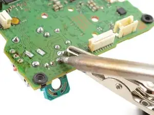
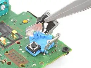
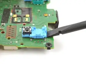
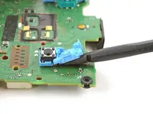
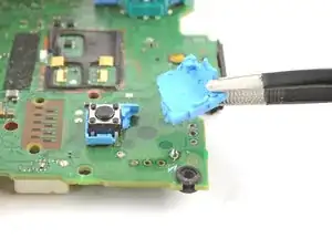
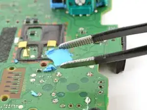
    • Schiebe einen Spudger mit dem flachen Ende unter den Kunststoffboden des Joystickmoduls.

    • Heble langsam nach oben, bis sich das Kunststoffteil verbiegt und von der Platine abbricht.

    • Entferne den Kunststoffboden.

  48. qkWhNv4ATQxUaU1d
    qkWhNv4ATQxUaU1d
    6TOwUWpLsOLxCQ2P
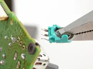
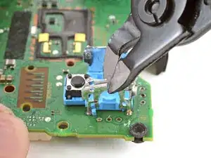
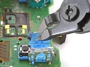
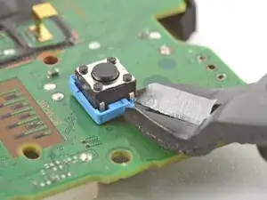
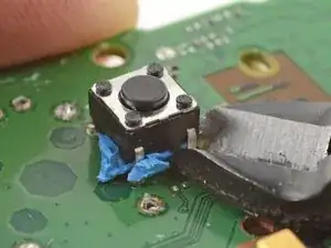
    • Trenne alle Reste des Kunststoffbodens mit einem Seitenschneider und einer Zange vom Taster ab.

    • Schneide die vier Beinchen des Tasters mit einem Seitenschneider von der Platine ab.

    This is kind of a dumb step. Probably better to just unsolder it from the back instead of cutting the pins... I wasn't really thinking/paying attention when I did this step and accidentally scratched the traces..

    Alex -

  49. 4xOHfy1iTsEDPZAK
    4xOHfy1iTsEDPZAK
    beZMjhfbKqkaVSiY
    • Entferne den Taster.

    • Entferne alle Reste von Kunststoff.

    Hi friend why not disorder all at once instead of ripping apart the joy stick ??? ?

    Victor -

    It makes it easier removing each piece one by one rather than the whole thing. I kind of wish I did this rather than removing the whole stick at once. Such a pain

    Brando Lopez -

  50. sKCdILZLy3mcxCiT
    sKCdILZLy3mcxCiT
    OnBATFtuUhRMeZnc
    • Erwärme eine der Lötstellen an den vier Beinchen des Tasters.

    • Wenn das Lötzinn geschmolzen ist, dann ziehe das Beinchen mit einer Pinzette aus ihren Durchsteckloch heraus.

    • Entferne in gleicher Weise die anderen drei Beinchen des Tasters.

  51. ioqSLFAmUPurfsQT
    ioqSLFAmUPurfsQT
    tp3OWkYKWhOkgROs
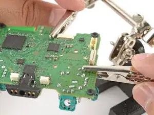
    • Fixiere die Hauptplatine so, dass du von beiden Seiten herankommst.

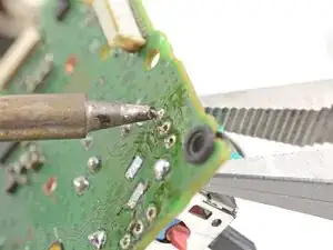
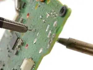
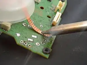
    • Erwärme eines der Durchstecklöcher von einer Seite mit dem Lötkolben.

    • Sauge das Loch von der anderen Seite mit der Entlötpumpe ab.

    • Erhitze das Loch nicht länger als fünfzehn Sekunden lang, damit das Lötauge nicht beschädigt wird.

    • Entferne eventuelle Lötzinnreste mit der Entlötlitze.

    • Beseitige auf gleiche Weise die Reste des Lötzinns von beiden Seiten der Platine für alle Durchstecklöcher.

  52. QDEKjSo1ZmKxNIGE
    • Kontrolliere alle Durchstecklöcher und achte darauf, dass sie nicht von Lötzinnresten blockiert werden. Wenn dies doch der Fall ist, wiederhole den vorherigen Schritt, um sie durchgängig zu machen.

  53. dvycFaaaIioDjOZt
    dvycFaaaIioDjOZt
    ME2DEaw4YZlFFDSE
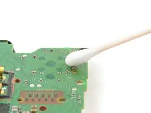
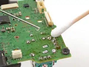
    • Tröpfle etwas hochkonzentrierten Isopropylalkohol (mindestens 90%ig) auf die Oberseite der Hauptplatine dorthin, wo das neue Joystickmodul sein wird.

    • Wische alle Reste vom Flussmittel mit einem Wattestäbchen oder einer weichen Bürste weg.

  54. wdMRu33oakEXJkWS
    wdMRu33oakEXJkWS
    e5CYjwVYkdJAxUJq
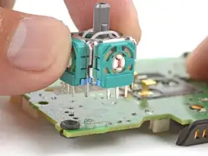
    • Platziere das neue Joystickmodul so auf der Hauptplatine, dass alle Anschlussdrähten durch die Löcher in der Platine gehen.

    • Drücke das Modul vorsichtig fest, so dass es flach auf der Platine aufliegt.

  55. TIqasIJQQUQos2YP
    • Drehe die Hauptplatine herum und fixiere sie so, dass du die Anschlüsse des Joystickmoduls verlöten kannst.

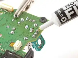
    • Trage etwas Flussmittel auf die Verankerungen des Rahmens auf, um sie für das Löten vorzubereiten.

  56. Genauere Hinweise für das Löten von durchgesteckten Bauteilen findest du in unserer <a href="../../Anleitung/Wie%2Bman%2BL%C3%B6tverbindungen%2Bherstellt%2Bund%2Bentl%C3%B6tet/750">Lötanleitung</a>.
    • Genauere Hinweise für das Löten von durchgesteckten Bauteilen findest du in unserer Lötanleitung.

    • Verlöte eine der Verankerungen des Rahmens mit der Hauptplatine.

  57. 6xqhRORd1yRsRGIM
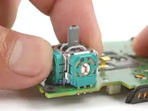
    • Achte darauf, dass sich das Joystickmodul immer noch flach auf der Hauptplatine aufliegt (wie gezeigt). Wenn das nicht der Fall ist, musst du die Lötstellen nochmals erwärmen und verschiebe das Modul.

  58. OmrGDFBKuWXlEhus
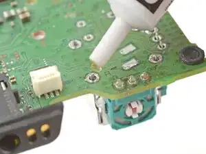
    • Löte alle vierzehn Lötstellen des Joystickmoduls auf der Hauptplatine fest. Benutze Flussmittel, damit das Lötzinn eine gute Verbindung herstellt.

  59. cMtt6c45oPuOuhCy
    cMtt6c45oPuOuhCy
    fwC4ExwTjASuFeeG
    • Tröpfle etwas hochkonzentrierten Isopropylalkohol (mindestens 90%ig) überall dort auf die Platine, wo noch Reste vom Flussmittel sind.

    • Benutze einen Wattestäbchen oder eine weiche Bürste und beseitige die Flussmittelreste.

    • Schaue deine Arbeit genau an:

    • Sind alle Lötstellen wohlgeformt?

    • Achte darauf, dass die Lötstellen keinen Kontakt zueinander haben.

    Awesome guide, easy to follow and made a time consuming task come out just a little better! Loving my new Hall Effect joysticks. Absolutely no drift after using the calibration tool. I appreciate the authors hard work and step by step pics! Thanks again!

    Nicholas Fleming -

Abschluss

Glückwunsch! Du hast die Joysticks deines Kontrollers ersetzt und zusätzlich deine Lötkenntnisse verbessert.

Um das Gerät wieder zusammenzusetzen, gehe zunächst zu diesem Schritt. Folge dann der Anleitung in umgekehrter Reihenfolge.

Lasse das DualShock-Kalibrierwerkzeug laufen, um den neuen Joystick zu kalibrieren.

Entsorge deinen Elektromüll sachgerecht.

Hat die Reparatur nicht ganz geklappt? Versuche es mit ein paar grundständigen Lösungen, ansonsten findest du in unserem Forum Hilfe bei der Fehlersuche.

Arthur Shi

Mitglied seit: 03/01/18

327049 Reputation

39 Kommentare

can I use Dualshock 4 joystick in the Dualsense ?

Kia -

Yes, the joysticks are the same in both controllers.

Wes -

How do you differentiate a real joystick part from fake ones? Since in my situation i can't order straight from sony.

TryJak -

I would suggest getting a PS4 Dualshock controller from the classifieds since there's a pile of them available for cheap and take the analogue stick from there.

Philip Sedlmair -

Thanks for the tutorial! I wonder if anyone has a problem after replacing the joystick? The controller simply won't turn on. If I connect the controller to either ps5 or my pc via usb, it will blink 3 times in orange and turn off. If I press the PS button when connected with usb, it will also blink orange 3 times and nothing happens. I've tried hard reset by using the hole on the back but it didn't help. Any advice??

zirimark -

Sounds like something went wrong during the repair. Maybe something wasn't plugged back in correctly? Maybe you removed more components than just the joysticks? Hard to say without knowing more. A quick search led me to a Reddit post that suggests that one of the ribbon cables might have been broken which seems likely as they're pretty delicate!

Joel Gillman -

ribbon cable causing a short, reassemble

Pedro Lopes -

How do I calibrate afterwards? I changed the sticks, but they need calibration.

marcpjensen -

I bought replacement sticks from GuliKit and they link to a third-party calibration tool that worked for me!

Adam Gordon -

Hello my controller wont start or charge after resoldering new joysticks any suggestions?

Thanks

Dominik Vlašič -

Hello, I have soldering Iron and pump but am having trouble removing the tiny of amount solder around the connections. any advice?

Heart -

heat gun, heat it up for about 5-10 min and the new module should snap right in

Albert Einstein -

Another option when trying to clean up the old solder to open up the through-holes is to use solder wick. I found that sometimes it helps to add a bit of your own solder first in order to be able to wick up the rest.

Adam Gordon -

Could I possibly only replace the potentiometer instead of unsoldering the entire unit?

Peter Roome -

Si es posible justo yo ando haciendo eso pero estoy reciclando unos potenciómetros de mando de PS4 al de ps5 ya que son exactamente iguales solo que también están dañados ando con prueba y error poco a poco para no dañar la placa y otro componente muy pequeño

Miguel López -

I broke my joystick R2 controller this can be repaired?

Devi Shree -

Great guide! I successfully replaced my joystick and it works perfectly. Definitely need a good solder iron, flux and a desolder pump.

tabitha roman -

there is differemce between ps4 and ps5 controller potentiometres...one is 2kOhm and one is 10kOhm so swappimg to another will make ur calibrations out of whack...so in theese comments people recommended ps4 sticks as replacement but those values would cause it to go out of whack....is there way to calibrate it without modboard or additional pot?

Riku Lehtonen -

Thanks for the guide! Definitely helped me out. I just wanted to add a comment because I think I have a different (possibly newer) version of the controller with a couple of small differences:

1. Starting in step 17, there are still four main ribbon cables to disconnect from the board, but they look slightly different and the ones on the sides of the board are narrower.

2. In step 24, there are two additional pairs of wires, 2 yellow and 2 green. They require the same steps as the black and red wires and there's even a Y on the board indicating which pad is for the yellow wire. Just desolder them and resolder them when you're done and you'll be good to go!

Adam Gordon -

Can this also be done with the V2?

name -

Is it possible for consumers to send defective controllers? We'd we willing to pay ifixit technicians for services like joy stick replacements with Hall Effect Upgrades and calibration.

Minh -

this is a little off from the norm but do

they make an adapter for the analog sticks so they can be flipped like a victrix controllers

johnathan0291 -

Grazieeeeeeeee

Avery Pellanda -

I've been practicing desoldering these things on old junk controllers while I wait for my joystick replacement to arrive and I've noticed I just can't seem to get all the solder out and so far, even using a solder wick. I can get it to a point where all the prongs look entirely clean, but the stick won't come out and I'm afraid of the fumes from melting the plastic by working on the other side of the board.

KeybladeSpirit -

Hallo ich habe eine Frage und zwar habe ich meine analog Sticks ausgelötet und danach alles mit Isopropanol gereinigt . Danach hab ich den neuen Hall Effekt Stick eingelötet und die Platine an einem gamepad Tester getestet.

Nach links und rechts steht der Stick perfekt nahezu auf null aber nach oben und unten steht der Stick auf Achse -1 und reagiert gar nicht.

Was hab ich da falsch gemacht?

Hardy 91 -

Thanks, the instructions were great, and now the stick drift is gone.

Leon -

kann man auch die sticks in den modulen tauschen oder sind dazu andere nötig?

Stefan Pirsch -

Thanks for the guide. Could you add a note to the PCB removal section about the rubber hole liners in the four corners of the PCB? They fall out easily and I just narrowly avoided losing one.

I also found a solder sucker to be ineffective. I used a hot air rework station set to 450f while pulling gently on the joystick to be removed and it came out peacefully after about 45 seconds. After that I used solder wick to clean up the holes. It’s not a tool that most people will have, though there are cheap ones on Amazon, but I wouldn’t have been successful without it.

Brian Josephs -

Even with experience soldering and de-soldering, for me the original joystick was very difficult to remove. Maybe with a hot air station it should be much easier. An important thing to know is after replacing the joystick you need to calibrate it because most probably it's going to be off its center. To calibrate it you can use the tool DualShock Calibration GUI from https://dualshock-tools.github.io/. Use Chrome or Edge, Firefox didn't work. After calibrating the joystick it works like it should. To calibrate it, first you need to connect the controller to a PC using a USB cable.

Franchesco R -

I've had issues after replacing the joysticks, but not with the joysticks themselves. It seems all the other buttons will randomly function even when not being used causing unintended turning on, spamming dpad, face buttons, bumpers and triggers. I removed all cables and motors before completely the installation, anyone else have this experience?

Josh Sadoway -

Just finished this repair and bought a heat gun from iFixit specifically for this repair! It was cheaper that buying a new controller plus it seemed like a fun/helpful tool to have around for other repairs.

I do not think I would have successfully gotten the original sticks out without the heat gun. I think a "hot air rework station" would have worked better than the heat gun I got. They look like they can push heat to a smaller area whereas the "gun" hits a broader area. Worth nothing that I also totally decimated (melted) the plastic hookup for the bottom mic but the controller still works fine without it!

Joel Gillman -

I've updated the guide with more details and an improved procedure. Hope it helps!

Arthur Shi -

Hello Sir,

I’m working on a PS5 DualSense (BDM-030) where I replaced both joysticks with GuliKit TMR modules. During removal of the original left stick, the LSX (left stick X-axis) trace was damaged.

Current symptoms:

Left stick only registers movement to the left, top-left, and bottom-left.

VCC is present (~1.8V).

Ground has continuity.

The LSX signal (middle pin) does not show continuity to any nearby components, so I believe the signal trace is broken.

I previously attempted a jumper to VCC by mistake, removed it, and confirmed the issue is specifically the LSX signal path.

I’m trying to locate the correct series resistor or via for the LSX signal on the BDM-030 board so I can run a proper jumper to the MCU side of the circuit.

Does anyone know:

The exact resistor designation for LSX on BDM-030?

A confirmed via location for that signal line?

A known safe jumper point for this repair?

Any boardview reference or photo guidance would be greatly appreciated.

Thanks in advance.

-Zeek

GhostPepper_Burn -

Isn't it easier just to use a hot air rework station to heat the solder with the board upside down let the joystick just drop out? Seems like alot or ripping apart for no benefit...

Freddie Hughes -

habe die sticks perfekt eingebaut doch beim bewegen der sticks passiert nicht und drückt im menü nur nach links

hat jemand bitte ein paar tips für mich wieso sie nicht gehen und was ich tun soll?

Aaron Klees -

Reiniciarlo , o descarga la app GamePad tester y lo conectas a tu móvil ahí viene el error o hay un programa en línea que calibra el joystick conectándolo a un cable en la PC

Miguel López -

Versuch mal die Sticks mit Kontaktspray einzusprühen. Das hat bei mir sehr gut funktioniert. Sogar ohne die Sticks zu tauschen. Mein Controller war 4 Jahre alt und nach der Reinigung so gut wie neu, als wäre er aus dem Laden gekauft worden :)

David Grumm -

Hello everyone,

I’m working on a PS5 DualSense (BDM-030) where I replaced both joysticks with GuliKit TMR modules. During removal of the original left stick, the LSX (left stick X-axis) trace was damaged.

Current symptoms:

Left stick only registers movement to the left, top-left, and bottom-left.

VCC is present (~1.8V).

Ground has continuity.

The LSX signal (middle pin) does not show continuity to any nearby components, so I believe the signal trace is broken.

I previously attempted a jumper to VCC by mistake, removed it, and confirmed the issue is specifically the LSX signal path.

I’m trying to locate the correct series resistor or via for the LSX signal on the BDM-030 board so I can run a proper jumper to the MCU side of the circuit.

Does anyone know:

The exact resistor designation for LSX on BDM-030?

A confirmed via location for that signal line?

A known safe jumper point for this repair?

Any boardview reference or photo guidance would be greatly appreciated.

Thanks in advance.

-Zeek

GhostPepper_Burn -

Hallo zusammen, ich bin neu in der Ifixit Community, ich habe das Problem gehabt das mein Controller einen Stickdrift hatte. Aber bevor ich neue Sticks mir zum löten besorgt habe, kam mein Schwiegervater auf die Idee es doch erstmal mit der Reinigung zu versuchen. Dies habe ich dann auch getan. Ich kann euch gerne auf Nachfrage die Mittel nennen die ich für die Reinigung verwendet habe. Aufjedenfall habe ich diese Anleitung hier verwendet, was mir sehr gut geholfen hatte bis zu dem Step an dem man die alten Sticks entlöten und die neuen Löten hätte müssen. Habe dann die Reinigung vollzogen indem ich unter die Sticks mit Kontaktspray gesprayt. Habe dann alles mögliche noch entfettet und dann den Controller rückwärts wieder zusammengesetzt und ohne das ich die Sticks austauschen musste, nur mit einer normalen Reinigung hat dies mein Problem behoben. Leider habe ich vergessen vorher und nacher Bilder zu machen, die hätte ich dann mit euch geteilt. Es hat unfassbar viel Spaß gemacht. :)

David Grumm -