
Introduction
Use this guide to replace the logic board in a 2019 MacBook Air.
Note that Touch ID will not function after replacing the logic board. The MacBook’s original Touch ID sensor is uniquely paired to the T2 chip on the logic board at the factory—and without Apple’s proprietary calibration process, even a genuine replacement logic board from another MacBook Air won’t work.
If you replace the logic board, you must install a paired Touch ID sensor to retain Touch ID functionality.
-
-
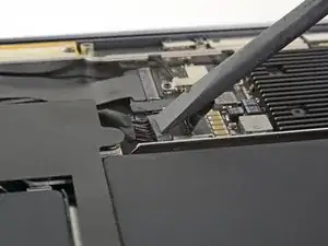
If your MacBook is running Big Sur v11.1 or later, disabling Auto Boot may not work. You can proceed normally, but make sure to disconnect the battery as soon as you're inside.
-
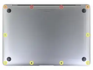
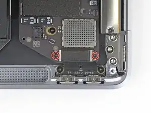
Use a P5 driver to remove the following screws:
-
Two 7.9 mm screws
-
Two 7.1 mm screws
-
Six 2.6 mm screws
-
-
-
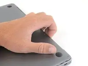
Wedge your fingers between the display and the lower case and pull upward to pop the lower case off the Air.
-
Remove the lower case.
-
-
-
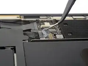
Use a spudger to slide the battery connector parallel to the logic board and out of its socket on the logic board.
-
-
-
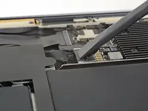
Use a T3 Torx driver to remove the two 1.4 mm screws securing the trackpad connector bracket.
-
Remove the trackpad connector bracket.
-
-
-
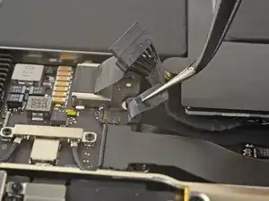
Slide the tip of a spudger underneath the left speaker cable and pry straight up to disconnect the speaker.
-
With the connector disconnected, slide the flat end of a spudger under the cable to separate the adhesive securing the cable to the logic board.
-
-
-
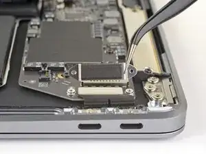
Use a T3 Torx driver to remove the two 1.3 mm screws securing the USB-C port connector bracket.
-
Remove the USB-C connector bracket.
-
-
-
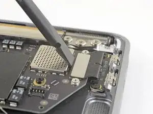
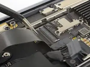
Use the flat end of a spudger to pry the USB-C cable connector up and out of its socket on the logic board.
-
-
-
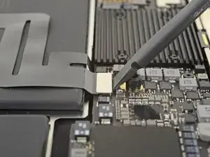
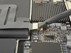
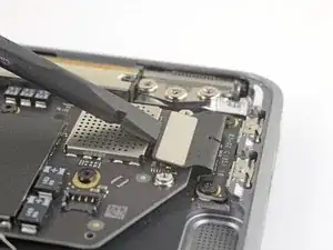
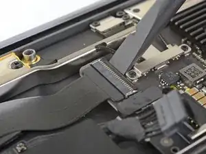
Use a spudger to lift up the small locking flap on the sound board cable's ZIF connector.
-
Slide the sound board cable out of the ZIF connector.
-
-
-
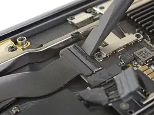
Use the tip of a spudger to lift up the locking flap on the fan cable's ZIF connector.
-
Slide the fan cable out of the ZIF connector.
-
-
-
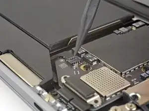
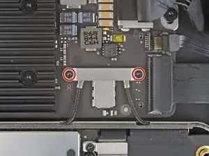
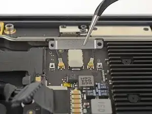
Use a T3 Torx driver to remove the two 1.4 mm screws securing the antenna cable bracket.
-
Remove the antenna cable bracket.
-
-
-
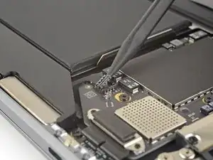
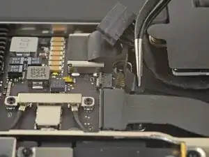
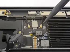
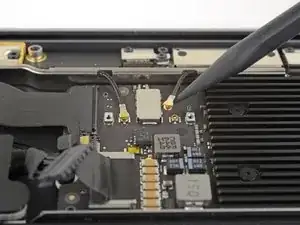
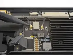
Insert the point of a spudger under one of the antenna cables close to the connector. Pry straight up to disconnect the cable.
-
Repeat for the other antenna cable.
-
-
-
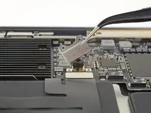
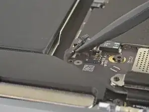
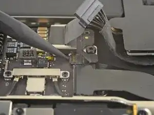
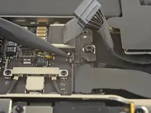
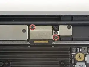
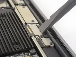
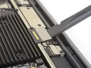
Use a T3 Torx driver to remove the two 1.5 mm screws securing the display cable connector bracket.
-
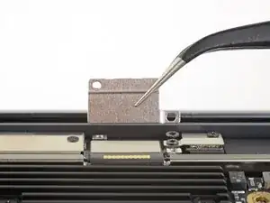
Remove the display cable connector bracket.
-
-
-
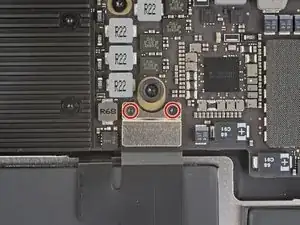
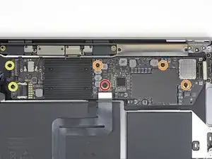
Use a T5 Torx driver to remove the following screws:
-
One 5.5 mm screw
-
Three 2.6 mm screws
-
Two 1.9 mm screws
-
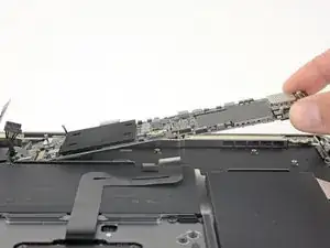
Compare your new replacement part to the original part—you may need to transfer remaining components or remove adhesive backings from the new part before installing.
To reassemble your device, follow the above steps in reverse order.
Take your e-waste to an R2 or e-Stewards certified recycler.
Repair didn’t go as planned? Check out our Answers community for troubleshooting help.

One comment
Consulta , para este modelo el cambio de pasta disipadora es diferente a modelos anteriores, es factible colocarle una HY510 HEATSINK?
A lo que voy es que yo desmonte un equipo, y lo revise y veo que la pasta esta medio seca.
If the first thing you do is disconnect the battery, is it really an issue if you don’t (or can’t) disable auto-boot?
maccentric -
I agree, why disable Auto-Boot when the lid is closed and the battery is disconnected immediately? – I've never had an issue since 2016 when the feature was introduced.
stevebsiegel -
On my machine, the longest two screws were in the corners, while the other two long screws were in the middle. Perhaps previous service in the past had them replaced into the wrong place? In any case, the longest screws do seem to fit in either place. I guess 0.8mm is not very much of a difference. Seems like poor design if they could have used one size of screw.
johann beda -