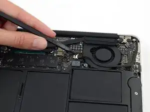
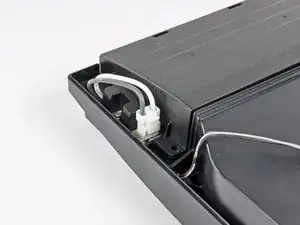
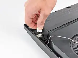
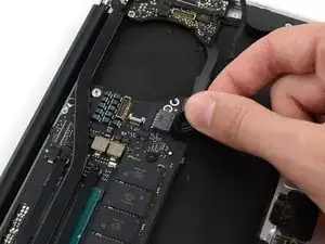
Introduction

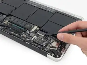
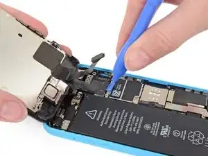
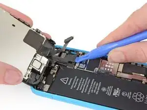
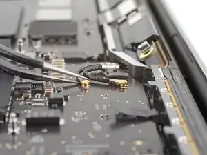
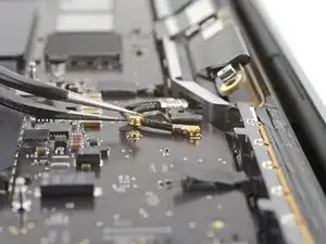
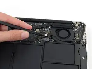
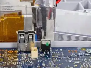
Modern electronics contain a dizzying array of internal data and power cable connectors—and nothing brings a project crashing to a halt like accidentally breaking a connector.

Use this guide to familiarize yourself with the most common types of connectors, and learn the tools and techniques you’ll need to disconnect (and reconnect) them safely.

  1. ZIF Connectors
  2. No-Fuss Ribbon Cable Connectors
  3. Flat-Topped (Low Profile) Connectors
  4. Press Connectors
  5. Coaxial Cable Connectors
  6. Display Cable Connectors
  7. Other Ribbon Cable Connectors
  8. Sliding Connectors
  9. Power Cable Connectors
  10. Bundled Cable Connectors
  11. Glued-Down Cables
  12. SATA Cables
  13. Soldered Connections
  14. Elastomeric (ZEBRA) Connectors
  15. Rare & Exotic Connectors
  1. KhCBl1NUOgLRtiFO
    KhCBl1NUOgLRtiFO
    TwNYHFVU1tD2oKgp
    DlhBYQ1QLgHnWQ5I
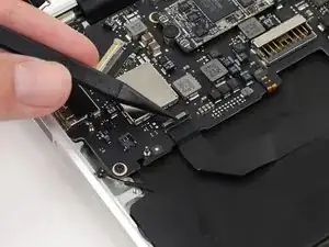
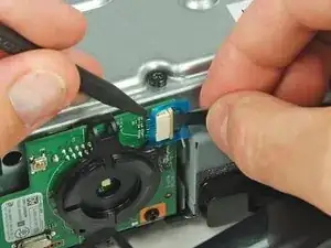
    • The zero insertion force (ZIF) connector often causes trouble for beginners. ZIF connectors are used to secure delicate ribbon cables, such as FFC (flat flex cables) or FPC (flexible printed circuit) cables.

    • As the name implies, no force is needed to plug in or remove the cable.

    • To disconnect the cable, use the tip of a spudger or your fingernail to flip up the small locking flap. Then, you can safely pull the cable out.

    • Be sure to pry up on the hinged flap, not the connector socket.

    • The white line on this ribbon cable marks the edge of the connection area. To reinstall, insert the cable into the connector up to this line, and then close the locking flap. If the cable doesn’t insert easily up to (or very near to) this line, it’s probably misaligned and needs to be gently removed and repositioned.

    What if I break the ZIF connector itself (were the ribbon goes), is my tablet ruin?

    elainegb27 -

    Unless you are good with a soldering iron or hot air station I would suggest taking it to someone that can do it.

    deswaite -

    “…Be sure to pry up on the hinged flap, not the connector socket….” but we’re not going to provide any further information than this and good luck with that :-)

    andyescribe -

    That’s what the photos are for—providing a visual example. There are a million different implementations of ZIF connector out there, so it’s not possible to provide specific instructions for each one in a single guide. For that, you need to search for the guide for your specific device. Unfortunately, looking at your post history, it appears you attempted to do that, but the guide you were following (Nexus 6) mislabeled the battery connector as a ZIF connector. I’ve corrected the guide. Sorry for the trouble!

    Jeff Suovanen -

    You have provide awesome tips which is very helpful. I have issue with FPC that not connecting with Cable

    Ralph Vale -

    hola he intentado cambiar el cristal de mi apple watch 2 despues de conseguirlo me he dado cuenta que he retirado el cable sin bajar la pestaña o no se que he doblado los pines despues de intentar una y otra vez el conector zip de la derecha ha quedado inservible es posible comprar ese conector en algun lugar o sabrian que nombre de conector debo buscar ya que no viene en ninguna expecificacion gracias

    Fran Ansio -

    Great tutorial, thanks. Had I not seen it, I would have irreparably damaged my keyboard. Perhaps it lacks a bit more guidance on how to place the cables back. I found that part to be the hardest actually.

    Juan Dueñas -

  2. rmVmYKBcl2B26BPH
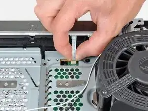
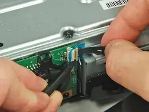
    • Sometimes you'll find a ribbon cable that simply pulls out of its socket, with no locking flap. The ribbon is normally sturdier than those used with ZIF connectors and the end is often reinforced with a stiff plastic film.

    • These connectors are often found on larger items such as printers, projectors and games consoles, such as this PS3 control board.

    • Before attempting to disconnect the ribbon, make quite sure this isn't a ZIF connector (previous step) with a release mechanism, otherwise you may damage the connector or the ribbon in forcibly removing it, and you won't be able to reinsert it.

    • To disconnect the cable, pull it straight out of the connector.

    • To reinstall the cable, hold it near the end and push it straight into the connector, being careful not to kink the cable. If you can, apply the force to the plastic reinforcement rather than the cable itself.

    How can I remove ribbon connect or of Sony Bravia led tv

    Sonali Likhare -

  3. ndk5I4rVRABXpiRO
    ndk5I4rVRABXpiRO
    JpEQYLC6aX63k6DB
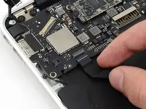
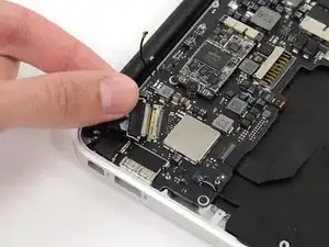
    • To disconnect flat connectors like this one, use a spudger to pry up each side. Then, lift the connector straight up from its socket.

    • To reinstall, carefully position the connector, and then press it straight down until it snaps into its socket. Finger pressure is all that is required. If it won't snap home it'll be because it isn't correctly positioned. Sometimes it can take a little patience to find exactly the right position.

  4. Nyg2mrZmEWSeebcm
    Nyg2mrZmEWSeebcm
    bSOeaFQXMnXEoEgG
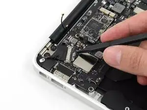
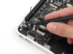
    • Smaller press-fit (or "pop") connectors may require a simple flick with a plastic opening tool, spudger, or fingernail.

    • Place the tip of your tool under the edge of the connector, and pry the connector straight up from its socket.

    • Be very careful to pry only under the edge of the connector, and not under the socket itself. If you pry under the socket, you will separate it from the circuit board, which requires specialized microsoldering skills and equipment to repair.

    • To reconnect, align the connector carefully over its socket and press down with your fingertip—first at one side, then the other—until it clicks into place.

    • Do not press down on the middle until the connector is fully seated—if it's misaligned, the connector can bend, causing permanent damage.

    I have an idea,/Request that I'm sure would be worth the effort, and fit right into this subject. how about a step by step guide on fixing the mistake of fudging up the socket yes on the mother board Guilty, right now it's a 500 dollar paper weight!! ! And I'm sure there's a long line of us,right guys, since you guy's are Awesome at it! Where to source the female sockets that's go onto the board and the proper steps and tecniques , would be greatly appreciated, keep up the great work!!

    JOE -

    Sorry to hear that! My usual advice would be to take it to a repair shop that performs board-level repairs (a.k.a. microsoldering). Replacing a damaged connector socket typically requires a lot of skill, practice, and tools that likely cost more than the full retail price of your device. So, it’s not exactly DIY-friendly! But if you’re interested, you can find a good introduction to board-level repairs on our YouTube channel.

    Jeff Suovanen -

    Is there a specific name for this type of connector? (brand, etc).

    David Schwartz -

    Stack-type Board-To-Board connector. JAE is a big manufacturer. FPC (Flexible Printed Circuit), what we commonly know as flex cables usually - is considered a board in this context.

    Jan Magne Skaue -

  5. iCCFFLGqFqByuWdX
    iCCFFLGqFqByuWdX
    3abDXcSjcbAt3fJX
    yBJyPeFYLJHHdnVu
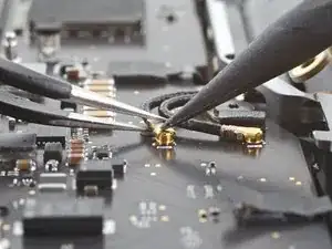
    • For small coaxial connectors, like these U.FL antenna cable connectors, slide a thin, ESD-safe pry tool or tweezers under the wire until it's snug against the connector, and pry straight up from the board.

    • To reinstall, hold the connectors in place and gently press them straight down. The connectors “snap” into their sockets much like the metal snaps on a jacket.

    Hello, I am repairing a tablet and the head to my coaxial cable fell off. What do I do?

    Brittany Dush -

  6. IkMIC5HEiNVgKYRR
    IkMIC5HEiNVgKYRR
    sTZPmuQor2nHrnCu
    vCOhqMqVi46oitfs
    • Display and camera cable connectors like this one sometimes have a small metal clip running around the back of the socket to lock them in place.

    • To separate the connector, gently push the tip of a spudger under the clip. Then, swing the clip over to the other side of the socket, so that it lays flat against the cable.

    • Holding the clip and cable together, gently pull in the direction of the cable to remove the connector from its socket.

  7. JcICVBKEc6THiWow
    JcICVBKEc6THiWow
    VGLcfLrJBX1VWJiV
    J5BqJBeO3iWWQepL
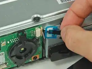
    • Here's another type of ribbon connector, commonly found on Xbox gaming consoles.

    • To remove it, use a spudger or fingernail to lift the clear blue tab away from the connector.

    • Next, use the tip of the spudger to push open the plastic locking tab.

    • The locking tab will only move about 2 mm.

    • Pull the ribbon cable out of the connector in the direction of the cable.

    i knocked the locking tab off… on three of them, any way to reattach them?

    John Baker -

  8. GeXDbaeNbNln2lUa
    GeXDbaeNbNln2lUa
    foKTDXDanCCRAeXt
    • Some connectors require a little coaxing before they’ll give up their cables. This tiny iSight camera cable connector has no convenient place to pry or pull.

    • At this point, some people give up and simply pull on the cable itself—which may work, but may also damage the cable.

    • To disconnect it safely, use the pointed tip of a spudger to carefully push on each side of the connector.

    • Alternating from one side to the other, gently “walk” the connector out of its socket.

    I used tweezers to open this connector

    Muescha -

  9. HqrBqLO1U4rAejcQ
    HqrBqLO1U4rAejcQ
    h6fkEiKEeTijRdHI
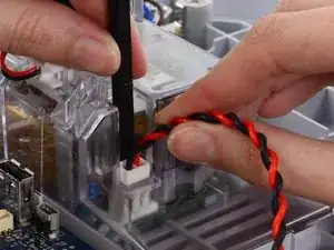
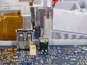
    • Power cable connectors like this one have a small tab on the side that locks them in place.

    • To separate the connector from its socket, squeeze the tab against the connector, and pull the connector straight up from the socket.

    • JST connectors are similar but don't have the locking tab. There are a few other similar types, with or without the tab, and having 2 or 3, sometimes up to half a dozen or more wires. These may be found connecting a microphone or speaker in a camera, or interconnecting the circuit boards in a radio.

    • Some variants are very small. If you try to disconnect them by pulling on the wires they may break. Ideally, pull on the body of the plug with a pair of tweezers, rocking it from side to side to ease it if necessary.

    Hallo, ich habe genau wie auf dem Bild bei meiner PS3 Slim ein ähnliches Kabel von dem Laufwerk zu trennen versucht. Beim Ziehen ist nicht das Kabel abgerissen, sondern die Anschlusstelle an der Platine hat sich auf einer Seite gelöst. Muss man hier nun das Teil wieder dran löten oder kann man es irgendwie mit Klebern fixieren?

    Stefano Aram -

  10. 1tRkF1V6xBOfpkuu
    1tRkF1V6xBOfpkuu
    ref1voL5QovbOTgK
    • If you see a cable made up of lots of individually wrapped wires leading into a single connector, pulling on the cable itself may be the best method.

    • Pull the cable away from the connector in the same direction as the individual wires are running.

    • Pull evenly on the full width of the cable so that no individual wires are overly strained.

  11. 5XdLQZbtkMdsQuUF
    5XdLQZbtkMdsQuUF
    fhPBMrdGfxDRXS2L
    • Sometimes removing the connector from its socket isn’t enough; an additional step or two is required to free up the cable. Here we have a Lightning port ribbon cable that is lightly glued into place.

    • To remove it, carefully slide a spudger or guitar pick underneath the cable, freeing it from the adhesive.

    • For particularly delicate or stubborn cables, a little heat from a heat gun, hair dryer, or our handy iOpener will help soften the adhesive.

  12. foXgCRAic2ZrQnqR
    • Some common internal power and data cables, like these SATA cables, work much like the regular audio/video cables you already have around the house.

    • To remove them, just pull in the direction of the cable.

    • Some variants of the SATA cable have a small release tab or button on the side.

    • Hold the tab down with your finger, and then pull to remove the cable.

  13. X461VjyAKivHLdLO
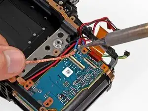
    • You'll also encounter wires that weren’t designed to be removed at all, and are in fact soldered into place.

    • Not to worry—a soldering iron and some soldering wick makes quick work of these little guys.

    • If soldering isn’t yet your thing, head on over to our soldering technique guide and learn a new skill!

  14. aNqEJRNhGYDTDkIN
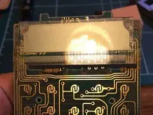
    • These are often found in pocket calculators, DECT phones, and other devices with a simple monochrome 7-segment or low-resolution display. They are used to connect the conductive tracks on the glass of an LCD to a set of pads on a circuit board below. (These displays sometimes suffer from dead segments or rows of pixels.)

    • Screws or twisted metal tabs commonly secure a metal frame, which compresses the elastomeric strip between the LCD and the circuit board. Release these to separate the LCD and the elastomeric strip.

    • In the photo, bright light reveals the conductive traces on the glass of the LCD. Beneath this is the elastomeric strip, and hidden beneath that are the tracks on the circuit board—in the same patterns as the ones on the glass.

    • The elastomeric strip consists of conductive and non-conductive layers which alternate along its length. There are several for every connection to the LCD, eliminating the need for precise alignment.

    Hi

    How do you fix this type of connection

    Do I need a special glue or just reheat with soldering iron

    Thank you

    Escee Escee -

    Nothing you can do with glue or a soldering iron. Disassemble and take out the elastomeric strip. Gently squeeze it sideways, i.e. in a direction perpendicular to its height. Gently clean the glass and the circuit board with isopropyl alcohol and reassemble making sure that the elastomeric strip is squeezed (in its height) as much as possible between the board and the glass. Alternatively, if you can get a replacement elastomeric strip of the same dimensions that would be even better but I think they’re only normally sold in large quantities to manufacturers.

    Philip Le Riche -

  15. W3vIVHNvEOVx21G5
    W3vIVHNvEOVx21G5
    SYEFGcXPCASGClcL
    oOtLg2XZFWkWkZi1
    • Eventually, you're bound to come across a connector that you've never seen anywhere else.

    • Inspect the connector carefully, and try to determine how it comes apart.

    • Work slowly, using lots of gentle wiggling. If your first attempt doesn't seem to be working, don't force it. Try another approach or see if a different tool gives a better result.

    • If you're still having trouble, search for guides for similar devices to see if they provide any clues, or ask for help in our Answers forum.

    Hi,

    I've just been wrangling with a 25ish year old Kenwood stereo. There were some connectors on it that I couldn't work out - which led me to this guide. The specific connectors aren't shown here. It turns out theybare spring-loaded, and you have to push the upper part (that I initially thought was a plug) down into the board - and this releases the ribbon cable. On the stereo, there are some shorter ones (8-pin), and some longer ones (15pin). On the longer ones, if you look close enough, they helpfully say ‘push' on them.

    I've taken some photos of you'd like to add them to this guide?

    J Salter -

Jeff Suovanen

Member since: 06/08/13

406688 Reputation

19 comments

Beautiful work. However, my modern LCD flat screen TV set uses the "No-Fuss Ribbon Cable Connectors" and I think they are fairly common in this application.

"Step 2 — No-Fuss Ribbon Cable Connectors

Occasionally, you'll find a ribbon cable that simply pulls out of its socket, with no retaining flap.

<snip>

These kinds of connectors are fairly rare, so check carefully for a way to release the connector before you resort to pulling on the ribbon cable."

Tom -

This was great! thanks for the detailed pictures. I have a question though on a very specific port used on apple tv 1.

here's the link to my post

What is the 4prong black port next the the IR plug?

Manny O -

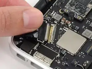
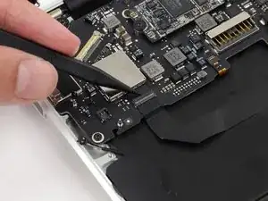
It's important to note that ZIF connectors often do require force to insert, for example the digitizer ribbon cable on the Nexus 6, which has a bit of negative tension from being curved. It has to be pushed in using the little raised portion with a fingernail, and held so the line on the cable matches the line on the PCB before closing the retention bracket or else it will not connect properly.
Benjamin Columbus -

I have a visio T-con board that has two flat ribbon connectors the one to the screen as a flip open latch you can do with your finger nail the other has a thin metal strip that over hangs the end on both sides. And ideas on how this one opens up? Rowland

rowlandstevens -

Great post!

Would be great if Jeff or someone could help me with my question, doesn't look as though that connector type is covered in the the post above. Its listed here - Need help with these Connector latches

TIA,

Norm

Norm -

good page, but I was looking for the display connectors for ipad air 2. They seem to just push on, but the pressure is so light I am not confident that they are seating correctly. It won’t turn on at any rate though the screen briefly comes up at boot.

FNorthrop -

Those are pop connectors—see Step 4. Align them carefully, and press them down; you should feel them click into place.

Jeff Suovanen -

I recently ran into a FFC (Flat Flex Connector) type I didn’t know how to open exactly, and this page only refers to the flip-lock type. Turns out it was a slide-lock connector and the diagrams on the page below were very helpful. I simply used my tweezers to push on the two tabs towards the cable, the actuator moved easily once you knew which way to apply force.

Doing ifixit versions of these diagrams would be VERY helpful.

Slide Lock Diagram: ''https://gct.co/Images/products/ffc-con...

Flip Lock Diagram: ''https://gct.co/Images/products/ffc-con...

Parent Page: ''https://gct.co/ffc-connector''

Googling to find these hints was VERY difficult not knowing the terminology. But this ifixit page was at the top of the stack, update to save the next guy half an hour googling?

(Updating to say you DO mention ‘sliding’ connectors… but the mechanism of the actuator is not very clear and/or the photos didn’t quite get me there, mine was a smaller pin-pitch I think too).

clickykbd -

@clickykbd This is a great idea! I’d love to add it to the guide. Do you mind sharing the name of the device you were working on, so we can try to get some photos of that connector in the wild? Or do you have some photos of your own? For copyright reasons, we usually can’t borrow other people’s images or graphics for our guides without permission. Thanks for sharing!

Jeff Suovanen -

Jeff, It was a Marshsall VLCD70MD-3G on-camera/field monitor. The connector was for the LCD ribbon flexible pcb cable.. I’ve still got it apart as I am trying to source a LCD, so I can try to get some half decent photos in a day or so. I’m pretty sure I’ve run into these before and they came apart with the “just pull” method… but reseating them without mangling the flat-flex was very difficult without knowing the trick if I recall. Thought I would do my homework this time.

clickykbd -

Bonjour

Je voudrais retirer un câble nappe écran sur la carte mêre de mon téléviseur LG 47LE5510 il y a dessus un petit levier qui se lève à l’ongle mais le câble semble collé et je n’ose pas forcer. Sur le connecteur est indiqué FS60 et le câble est un EAD60974135.

Pouvez-vous m’aider car je ne voudrais rien casser et ces 2 câbles coûtent cher en piece détachée.

Merci d’avance

blac3 -

Thank you, thank you, thank you. My husband really needed this.

Donna M. Hines -

Some ZIF ribbon connectors I’ve found, have the latch on the side of the insertion of the cable, some others on the oposite side. So be sure to pull on the correct side, or you will damage the connector. Another tip is to pull them very gently and when closing it, also with not much pressure, I have spoiled some hinges in the process, what is left to do is replace the whole connector.

luislupo -

Great article, but just one question… WhatWhat happens if you break one of these? Can you suggest a fix for something like the ZIF connector.

Is it pretty much a write off if you snap the latch on some of these connectors?

Nadim Sawaya -

I have a 3D printer from China, it is an Artillery Sidewinder X1 v4 model .  It uses ribbon cables from the power supply to the heated nozzle and the heated print bed.  It is my understanding that power is sent along a couple (or more) of the wires to distribute the load, and I get a good deal of heat at the connector site, on the ribbon cable itself. It is enough heat that I believe the connection and/or the ribbon cable itself will fail.

It is a friction fit connection and I imagine it is difficult to keep the connections inline at the connecting point.  The printer uses 20 wire and 30 ribbon wire cables as can be seen at: https://www.amazon.com/Artillery-Ribbon-...

My question, and I do understand the value of your time, is  – what can I do to better align the connections?  Is there some sort of heavier gauge ribbon I can use and, perhaps, do so through some sort of adapter at the connection point?

Anything you can suggest is appreciated.

Jim Kennedy -

Hi,

i need the connector in step 10.

Where can i buy this?

Thank Manuel

Manuel Otocki -

Merci : très clair et complet. Je vais pouvoir aider un ami à rebrancher le connecteur de son GPS

Vincent Le Duc -

how to fix a connector that's overheated and the clamp on top of it got melted or broken? Can I still force flex cable to connect to the connector? Thanks!

John Z. -

Outstanding web page!!!!

Robert -