
Introduction
Pre-req only
Tools
-
-
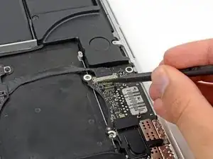
Use the tip of a spudger to flip up the I/O board data cable lock and rotate it toward the battery side of the computer.
-
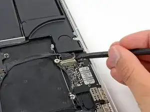
Use the flat end of a spudger to slide the I/O board data cable straight out of its socket on the logic board.
-
-
-
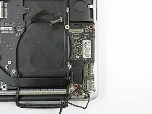
Remove the two 3.1 mm T5 Torx screws securing the I/O board to the logic board.
-
On some models, also removing the silver 3.5 mm T5 Torx screw from the heatsink can aid in I/O board removal.
-
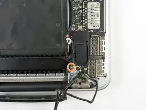
Carefully lift the I/O board and remove it from the lower case.
-

Conclusion
To reassemble your device, follow these instructions in reverse order.

This is a difficult step. A few images for the removal of the cable would be good/better
Robert Jan Lebbink -
Yes, a few more detailed pics here would help. Indeed, general pics explaining HOW ALL the plugs and sockets fit would be VERY handy :-)
Simon Anthony -
Here is that guide!
Carsten Frauenheim -
I helped me to use the pliers both to get underneath the canble lock and then push on the wings of the cable.
Calvin Truong -
Used fingers on the cable lock.
Joseph Gorse -
gently use tips of tweezers at either side to walk it out
Christa -
It is much more easy to do step 21 before step 20 - this cable is more easy to remove
Also if you assemble then do step 20 before step 21 - it is more easy to place the cable into the connector
Muescha -