Introduction

Prereq-only

  1. YmmpBdxUK4cDnJ1F
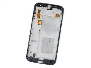
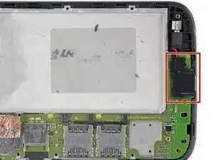
    • Peel up and remove the black rubber cover from the charging port and vibration motor connector.

  2. ZRNw4pUtObOGYQPs
    ZRNw4pUtObOGYQPs
    FdFQRbSjXmCfA5iL
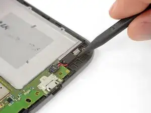
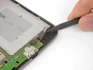
    • Insert the point of your spudger underneath the vibration motor, and gently pry up to separate it from the frame.

    • You don't need to completely detach the vibration motor; it can stay wired to the motherboard.

  3. XcrnfjAagKJo1stf
    • Peel up the copper tape covering the display connector.

    • This tape provides protection from electromagnetic interference. Keep it in one piece if possible, and carefully fold it back into position when your repair is complete.

  4. ZVfEwVMvRPehELg3
    ZVfEwVMvRPehELg3
    ZNRlh3XmjxvpZ4uR
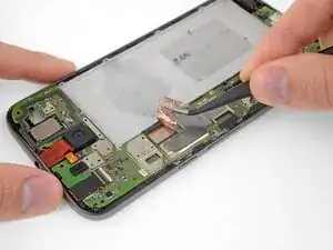
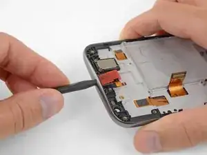
    • Use your spudger to disconnect the display by prying its connector straight up from the motherboard, on the edge nearest the side of the phone.

  5. dhwHcnJEyjMjK2xp
    dhwHcnJEyjMjK2xp
    IYVnbYUx56rG2ZoZ
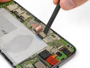
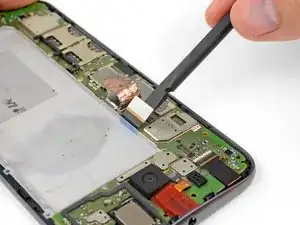
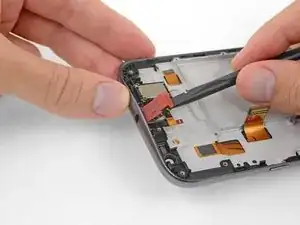
    • Pry up with your spudger to flip open the locking flap on the headphone jack's ZIF connector.

    • It's possible to disconnect the headphone jack at this point by pulling its orange flex cable straight out of the ZIF socket, but it's easy to tear the cable if you're not careful. For a better method, continue with the steps below.

    The orange flex cable is glued to the motherboard at the ‘A’ mark on the corner. Make sure to pry them apart before trying to remove the motherboard or pull the cable out of the ZIF socket.

    Donald Diviney -

  6. JFDkSBacP5TMjTmx
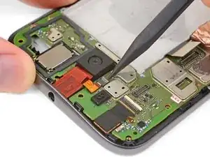
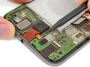
    • Use a T3 Torx driver to remove the two bronze-colored, 2.4 mm screws securing the motherboard.

  7. Q1GfIuDalTQCVYhl
    Q1GfIuDalTQCVYhl
    tGoXRlHP5FIqvWmB
    IS2IUYALQM1ffrQM
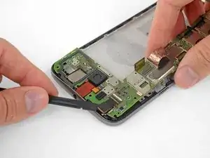
    • Grasping the motherboard by its edges, left the bottom end up at an angle, while keeping the top edge close to the phone.

    • Use your spudger to pry up the front-facing camera and make sure it separates safely from the frame. The camera can remain attached to the motherboard.

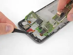
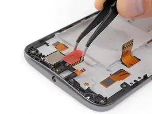
    • Using your tweezers, grasp the headphone jack flex cable and carefully pull it out of its socket as you remove the motherboard.

    • Remove the motherboard.

    • If you feel any resistance, stop. Make sure there are no components still holding the frame to the motherboard.

  8. JVOGFN6GTyxOaAgG
    JVOGFN6GTyxOaAgG
    1DdpykN2w35fTypG
    Q1YKyhQdIXcT3bvJ
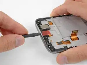
    • Insert the point of your spudger into the headphone port, and pry straight up to separate the headphone jack from the frame.

    • If needed, pry from the opposite side of the headphone jack to finish separating it.

  9. gP6pJsrhL6GuZV2G
    • Remove the headphone jack.

  10. Fpi1CxNZOnEwGYYs
    Fpi1CxNZOnEwGYYs
    IXnXk1WIPOGHheow
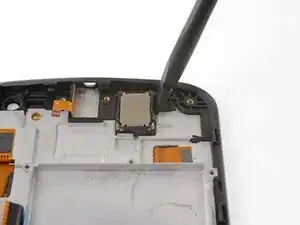
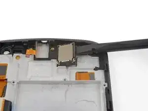
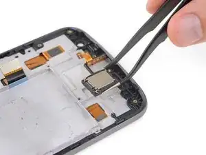
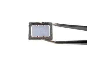
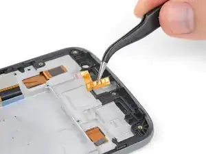
    • Using the flat of your spudger, pry up on the upper right edge of the earpiece speaker to separate it from the frame.

    • Strong adhesive secures the earpiece speaker. If necessary, apply heat or a few drops of isopropyl alcohol to help weaken the adhesive and make it easier to remove.

    Bei meinem verschickten iFixit Ersatzteil war der Lautsprecher schon drinnen - ich musste ihn also nicht aus dem alten Teil herausnehmen.

    Matthias Uiberacker -

  11. VrDvt4ZRgtgpTyW4
    VrDvt4ZRgtgpTyW4
    GiA1QpQLriPPXPZJ
    • Remove the earpiece speaker.

    • Check the condition of the adhesive around the bottom of the earpiece speaker when you reinstall it. A little heat from a hair dryer or iOpener can help soften the adhesive and make it sticky again. Be careful not to touch or damage the surface of the speaker.

    • In some of the previous photos in this guide, the speaker is shown installed incorrectly. During installation, make sure the speaker's two spring contacts are located at the bottom corners, as shown in the first image in this step. Images showing the speaker rotated 180° (with the spring contacts near the top edge of the phone) are incorrect.

    Bei meinem verschickten iFixit Ersatzteil war der Lautsprecher schon drinnen - ich musste ihn also nicht aus dem alten Teil herausnehmen.

    Matthias Uiberacker -

  12. MGo2khjk4jnl3uls
    MGo2khjk4jnl3uls
    QUxbKpOSIcqRcidl
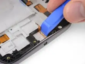
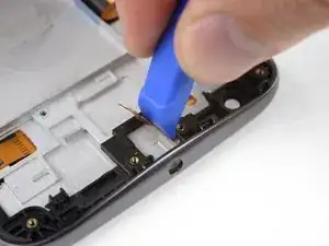
    • Wedge the sharp edge of your iFixit opening tool between the headphone jack flex and the plastic frame it's adhered to.

    • Carefully press down to separate the headphone jack flex cable from the adhesive securing it.

    • Don't use too much force, or you may damage the flex cable. If necessary, apply heat or a few drops of isopropyl alcohol to help weaken the adhesive and make it easier to remove.

    Achtung! Das Bild ist leicht irreführend, da das Öffnungswerkzeug hier direkt beim Flachbandkabel ansetzt. Das Flachbandkabel sitzt aber noch auf einem weißen Plastikplättchen, welches dann am Gehäuse klebt. Die Klebung zwischen Flachbandkabel und Plättchen ist kaum zu lösen und soll auch nicht gelöst werden. Das Plastikplättchen muss vom Gehäuse gelöst werden. So kann man das Flachbandkabel samt Plastikplättchen gut herausbekommen.

    Matthias Uiberacker -

  13. Ba4L4nXTIfMOwqgC
    • Remove the headphone jack flex cable.

  14. eOtAK2XvjPf4LDrY
    eOtAK2XvjPf4LDrY
    NHCxNicoZZyQLPOU
    tTOYXHggPg2Lto5l
    • The two case buttons (power and volume rocker) are each secured with two mushroom-shaped pins.

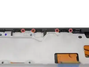
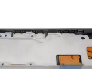
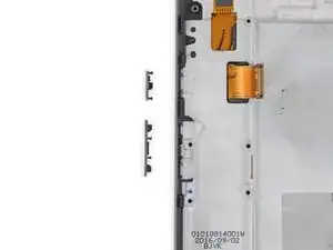
    • In the following steps, you'll apply pressure to these pins from the inside in order to remove and transfer the buttons.

  15. wmMYpPjtR6iRpr2j
    wmMYpPjtR6iRpr2j
    cM2BxafRSpRRavgG
    apxhKEaUuntpmfEB
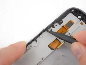
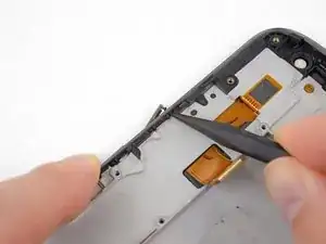
    • Push the power button out of the frame from the inside by carefully pressing the tip of your spudger against the tops of the two mushroom pins securing it.

  16. 3lWbUCvRl21k3x3t
    • Repeat the previous step to push the volume rocker button out of the frame.

    • During reassembly, press the buttons gently into the frame in the orientation shown here.

  17. DULURCHydyFxbGwJ
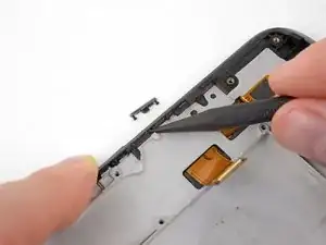
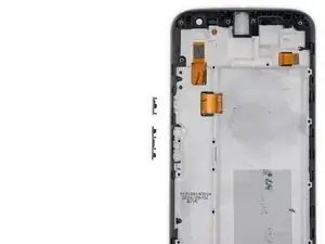
    • Only the LCD screen and digitizer assembly (with frame) remains.

    • Check carefully to make sure your replacement part matches, and that you've removed all the necessary parts from the old frame for installation in the new one.

    I was about to order the replacement screen from ifixit but I notice that the phone I want to fix does not a volume rocker switch but two separate switches - one for volume up and a separate one for volume down. The model number is Moto G4 and the SKU is XT1622. Can I still buy the replacement screen from ifixit?

    Graham Gullett -

Conclusion

To reassemble your device, follow these instructions in reverse order.

Jeff Suovanen

Member since: 06/08/13

406754 Reputation

0 comments