Introduction

Rear camera replacement on the Motorola Moto G4 is a feasible job, and by following this guide you can do it yourself!

  1. amtvddjAmwhmrnqH
    amtvddjAmwhmrnqH
    OWi4m4XCxfEBgDMt
    EwJnFXXfcwhAWbTc
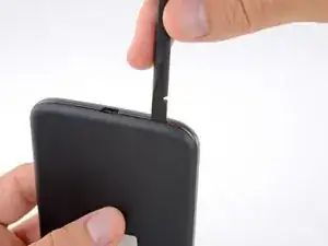
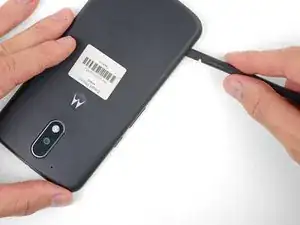
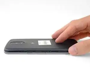
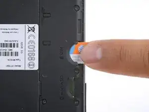
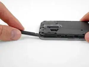
    • Insert a fingernail or a spudger into the notch on the bottom edge of the phone, near the charge port.

    • Gently twist or pry to open a small gap between the back cover and the body of the phone.

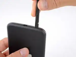
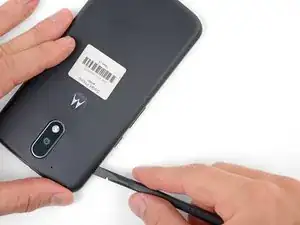
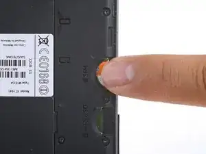
    • While keeping your tool (or fingernail) inserted into the gap between the back cover and the body of the phone, slide it around the corner to begin loosening the plastic clips holding the cover in place.

  2. HLqMHMbmASfwFDVU
    HLqMHMbmASfwFDVU
    wkbdCQWZyeoURicu
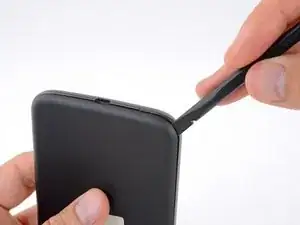
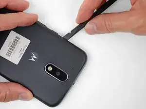
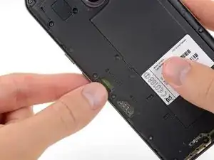
    • Slide your tool all along the side of the phone to separate more of the clips securing the back cover.

  3. IRICjJRMR1eUHQvd
    IRICjJRMR1eUHQvd
    frOdNGBIe3yRUYUQ
    DJCAEbwhl6ZN2xON
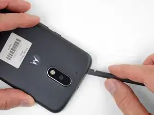
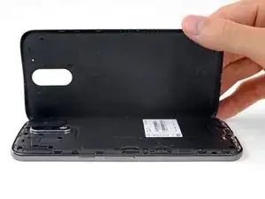
    • Keep your tool inserted slightly under the back cover, and slide it around the top corner.

    • If necessary, continue prying around the remaining edges of the phone until the back cover comes free.

  4. pTETy5GBsJCUgxsO
    pTETy5GBsJCUgxsO
    vKqBpOYKSASlbQkv
    • Remove the back cover.

    • To install the back cover, carefully position it over the phone and then press gently all around the edges until you feel the clips snap into place.

  5. ffDFM5MxvYRYGd3M
    ffDFM5MxvYRYGd3M
    NYHgWQmG4Q2DuDgh
    ulSaaiHbAaibtRYg
    • Push to eject and remove the MicroSD and SIM cards (if installed).

  6. CblUBFHebOPfmwHn
    CblUBFHebOPfmwHn
    Y5AmMCGdT5C4OWM1
    • Use a spudger to pry up the rubber cover for the camera flash connector.

  7. MBcHXGXsJATGCWMj
    • Remove the rubber cover.

  8. 2PT4qZOgF5piDHIy
    2PT4qZOgF5piDHIy
    OALHZ2QuglNBlykt
    • Use a spudger to disconnect the camera flash connector by prying it straight up.

  9. R52jISsgc6PJMUYW
    • Use a T3 Torx driver to remove the nineteen identical 3.1 mm screws securing the midframe.

    In my kit, the T3 Torx bit came in the ‘repair part’ box, while a T5 Torx bit was in the ‘repair tools’ box.

    Joseph Albert -

    my phone had t4, not t3

    Donald Smith -

    Screws are stuck quite hard, apply a hefty amount of pressure when removing. Otherwise you’ll destroy the thread

    face -

    unable to remove 8 of the screws. any suggestions?

    wayne malcom -

    My T4 is the tool that fit. I can see why people strip these. They were dam tight for such little screws.

    I also had a tough time getting them out of the socket once loose. Magnet in the tool was not very strong. I used my tweezers, and scratch the screw heads. That means they are real soft steel, and strip easy.

    P 38 -

  10. CdvPqSLWgj4YR1Im
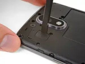
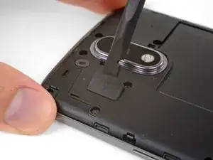
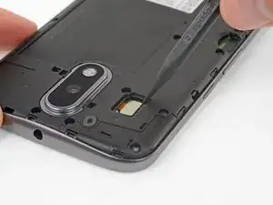
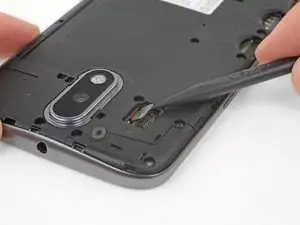
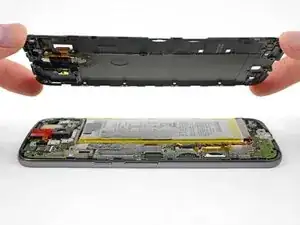
    • Insert a spudger under the midframe at the top left corner, and gently twist to separate it from the body of the phone.

    I couldn’t get the spudger in, but had success with the opening pick instead.

    Bernd Mast -

  11. D5HjSM3XUBUJOE6T
    • Remove the midframe.

    During the midframe removal, be careful and do not put too much torsional stress on the loudspeaker pickup wires (to the right of the main camera). It’s not that difficult to crush or shear the pickups there. Doing so will render your phone silent.

    Kevin Kwan -

    Exactly what happened to me. Both contacts broke off and if just loosely put where they were, they can't make proper contact anymore.

    There should be a warning about this in the guide itself!

    Simon Vetter -

  12. fGFKgOBXsMKoWbQr
    fGFKgOBXsMKoWbQr
    Zqb15SXcygILmYyg
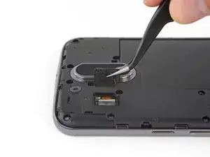
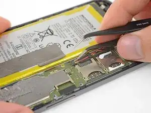
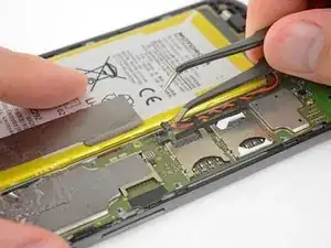
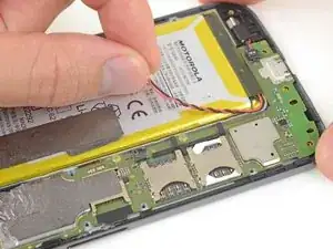
    • Insert a thin tool (such as one of your tweezer tips) under the red and black battery wires, and slide it underneath the battery connector.

    • Gently pry straight up to disconnect the battery.

    • Pry only from the side where the wires attach to the connector—if you pry anywhere else, you may break the socket.

    • During reassembly, align the connector in its socket and then press straight down to reconnect it, wiggling slightly as you press to help it seat correctly.

  13. 6w2GwPSNoZExnSmk
    6w2GwPSNoZExnSmk
    SdwF2lf4tHoLh5CS
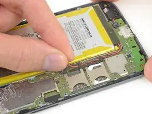
    • Peel off any tape securing the battery wires, and then push the battery wires towards the battery to de-route them from the black bracket on the motherboard.

  14. jDaTEHDKXWaoiy1A
    • It's not necessary to remove the battery in order to remove or replace the motherboard. You can safely ignore the fact that the battery is missing in the remaining images in this guide.

    • Peel up and remove the black rubber cover from the charging port and vibration motor connector.

    my headphone connecter broke off because instructions unclear…

    kevin9mai -

  15. XaESwKrUfHZVCj3D
    XaESwKrUfHZVCj3D
    TXLT1udDkpjNeVRl
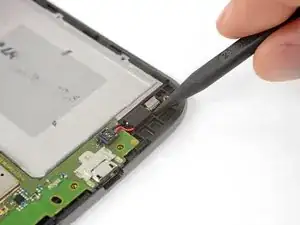
    • Insert the point of your spudger underneath the vibration motor, and gently pry up to separate it from the frame.

  16. yNFCygQtnsqU5jK4
    • Peel up the copper tape covering the display connector.

    • This tape provides protection from electromagnetic interference. Keep it in one piece if possible, and carefully fold it back into position when your repair is complete.

  17. LtTVhMIoXRCTtTSR
    LtTVhMIoXRCTtTSR
    LrOurZrfSarQEJ3E
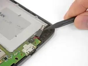
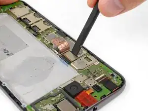
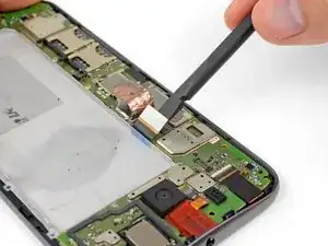
    • Use your spudger to disconnect the display by prying its connector straight up from the motherboard, on the edge nearest the side of the phone.

  18. YmaaQHlX1OSTVT26
    YmaaQHlX1OSTVT26
    bHA6gct4gM43oGwZ
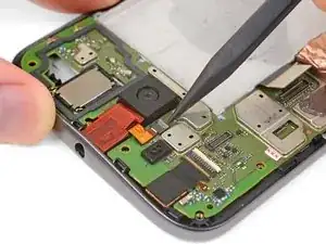
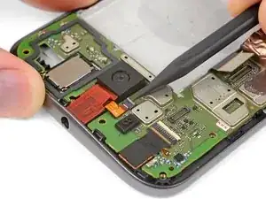
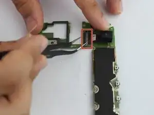
    • Pry up with your spudger to flip open the locking flap on the headphone jack's ZIF connector.

    • It's possible to disconnect the headphone jack at this point by pulling its orange flex cable straight out of the ZIF socket, but it's easy to tear the cable if you're not careful. For a better method, continue with the steps below.

  19. vHT2kBVhTXRmVAXy
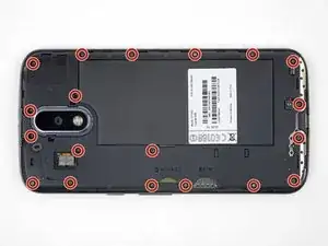
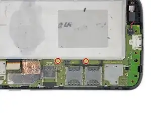
    • Use a T3 Torx driver to remove the two bronze-colored, 2.4 mm screws securing the motherboard.

  20. r4IECGfW6Ib62SkG
    r4IECGfW6Ib62SkG
    IsgUMCXVGCwMrUHV
    bTD2jQGMF2IOuphS
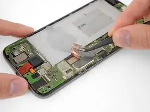
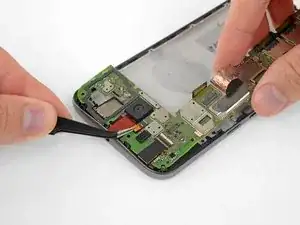
    • Grasping the motherboard by its edges, left the bottom end up at an angle, while keeping the top edge close to the phone.

    • Use your spudger to pry up the front-facing camera and make sure it separates safely from the frame. The camera can remain attached to the motherboard.

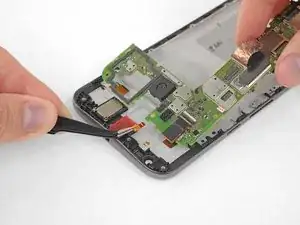
    • Using your tweezers, grasp the headphone jack flex cable and carefully pull it out of its socket as you remove the motherboard.

    • Remove the motherboard.

    • If you feel any resistance, stop. Make sure there are no components still holding the frame to the motherboard.

    • If desired, remove the remaining components from the motherboard (cameras and vibration motor).

  21. PIOWJ6UqSxfTcQW1
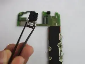
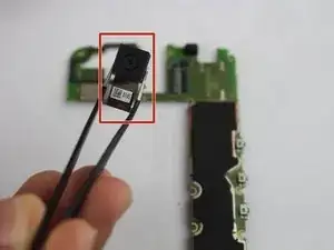
    • Flip motherboard over to access the rear camera.

    • Peel up orange tape and remove to access the top of rear camera motherboard clamp.

    • Flip up the black tab on the ZIF connector to detach the rear camera.

  22. InCi2CfFy5BQekKs
    • Remove rear camera from motherboard.

  23. MSnuIWtM5UQufAWh
    MSnuIWtM5UQufAWh
    D4KlXA2WbIYydnp3
    jjaWnYXDgJiBx5UV
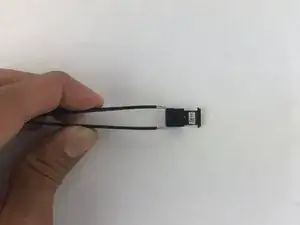
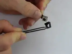
    • Separate the black plastic cover from the broken rear camera you removed.

    • Glue black plastic cover onto the new replacement rear camera.

Conclusion

To reassemble your device, follow these instructions in reverse order.

Nathan Granger

Member since: 12/02/18

202 Reputation

0 comments