Introduction

Use this guide to replace the screen on your Moto G6 Play, including the midframe which is glued to the display.

Make sure your replacement part includes both the display and the midframe—this guide does not cover separating the display from the midframe.

If your battery is swollen, take appropriate precautions.

This procedure involves removing the battery, which may be damaged during the removal process. We strongly advise you do not reuse the battery as doing so may pose a safety hazard. Replace it with a new battery.

  1. 6RN4H6eNuFsNRqlg
    6RN4H6eNuFsNRqlg
    UAeyROScU2nea22V
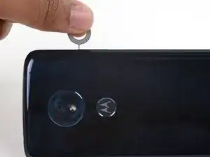
    • Insert a paperclip or SIM card eject tool into the small hole in the SIM card tray on the upper right edge of the phone.

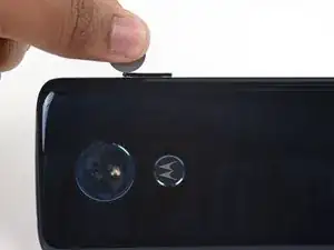
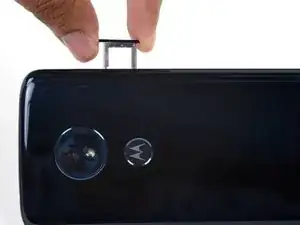
    • Press the tool into the hole to eject the tray.

    • This may require a significant amount of force.

    • The ejection mechanism is deeper in this phone than others and may require a longer SIM card eject tool. If your tool isn't long enough to reach the mechanism, try using an unfolded paperclip instead.

  2. LKAePyvgG5SRnYWk
    • Remove the SIM card tray.

    • When reinserting the SIM card, ensure that it is in the proper orientation relative to the tray.

  3. uOWkA1PyYeSJmcOP
    • Power your phone off before you begin.

    • If possible, drain the battery before disassembly. When the battery is charged, there's an increased risk of a dangerous thermal event if the battery is overheated or damaged during repairs.

    • If the rear glass is cracked, completely cover it with packing tape to contain the glass shards and avoid injury.

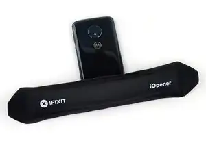
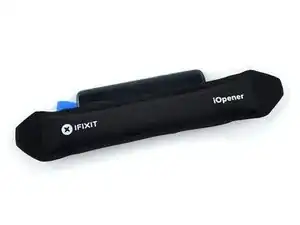
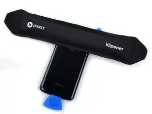
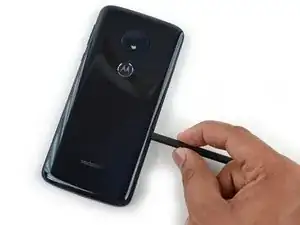
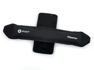
    • Prepare an iOpener and heat the back of the phone along its bottom edge for about two minutes, or until it's slightly too hot to touch. This will help soften the adhesive securing the rear glass.

    • You may need to reheat and reapply the iOpener several times to get the phone warm enough. Follow the iOpener instructions to avoid overheating.

    • A hair dryer, heat gun, or hot plate may also be used, but be careful not to overheat the phone—the display and internal battery are both susceptible to heat damage.

  4. diqQIWRrTuC4OQMJ
    diqQIWRrTuC4OQMJ
    NSWBolD5xQxMIdA5
    CVhDA2ZSFtgDRx5G
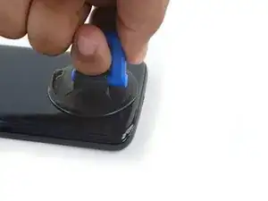
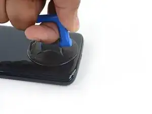
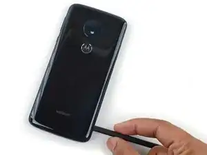
    • Apply a suction cup to the bottom edge of the rear glass.

    • Pull up on the suction cup with firm, constant pressure to create a slight gap between the rear glass and the frame.

    • If the glass is cracked, the suction cup may not stick. Try lifting it with strong tape, or superglue the suction cup in place and allow it to cure so you can proceed.

    • This may require a significant amount of force, but you only need to open a very slight gap with the suction cup to insert your tool.

    • If you have trouble, apply more heat to further soften the adhesive, and try again. The adhesive cools quickly, so you may need to heat it repeatedly.

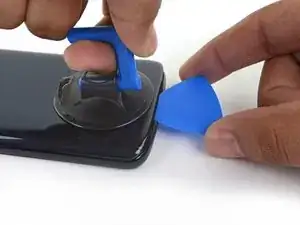
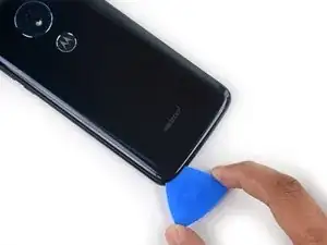
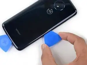
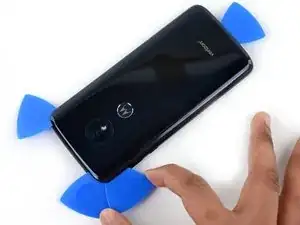
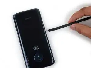
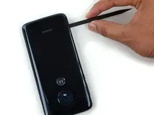
    • Insert an opening pick into the gap you created under the rear glass.

    If you are having no luck getting the bottom to lift, even when it's almost too hot to touch, try starting on a side near the bottom. The adhesive for the bottom was twice as wide as on the sides and even giving up on the iOpener and using a heat gun I could not get the bottom to lift at all, so I moved to the bottom left side and started there.

    No Spam -

    YES. This is the way. Thank you!

    mttwlk -

    Thank you for this comment! Completely agree. I was having no luck starting with the bottom and things worked much better when starting on the side.

    Laura -

  5. XS2YCQt2PlTsA6NX
    XS2YCQt2PlTsA6NX
    DntRXvEHULB14NuA
    1vWYAmbtMoMDgtbw
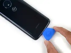
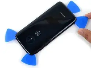
    • Slide the pick all along the bottom edge of the phone to slice through the adhesive securing the rear glass.

    • Slow down and slice very carefully as you get to the corners. The curved part of the glass along the left and right edges can crack very easily if the pick pushes up against the curved glass.

    • After being cut, the adhesive will sometimes stick back together as it cools. To prevent this, leave the pick under this edge after cutting, and continue the next steps with new pick.

  6. tngQPjZPSUi5YVHf
    • Heat the right edge of the back of the phone to soften the adhesive underneath.

  7. OvPEREXnxlaZIbGA
    OvPEREXnxlaZIbGA
    sJ6O2M2ML2FYHOdV
    sEDAqTYIp3B22PCl
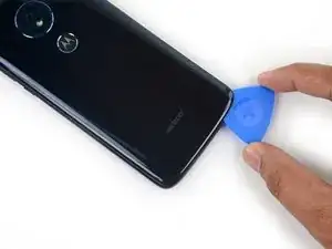
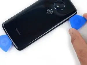
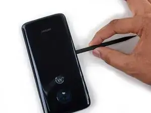
    • Slide the pick along the right edge of the rear glass to separate the adhesive underneath.

    • Take care to not insert the pick more than ~1 cm past the edge of the rear glass to avoid damaging the fingerprint sensor cable.

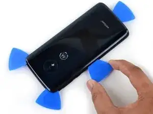
    • Leave the pick under the top right corner of the glass to prevent the adhesive from re-adhering. Continue with a new pick.

  8. taGDrOHjf1uMNZyo
    • Heat the top edge of the back of the phone to soften the rear glass adhesive.

  9. pTCGRtXQaTsSM1mg
    pTCGRtXQaTsSM1mg
    BQ5FMryafwZVT2Tc
    6dYbcQHbbTZtJyZO
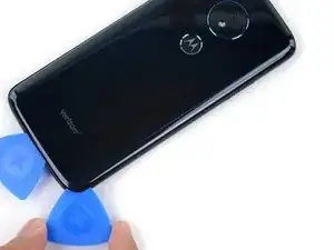
    • Slide the pick all along the top edge of the phone to slice through the adhesive securing the rear glass.

    • Take care to not insert the pick more than ~1 cm past the edge of the glass to avoid damaging the thermal dissipation pad surrounding the camera bump.

    • Slow down and slice very carefully as you get to the corners. The curved part of the glass along the left and right edges can crack very easily if the pick pushes up against the curved glass.

    • Leave the pick under the top left corner of the glass to prevent the adhesive from re-adhering. Continue with a new pick.

  10. TFRgxGDNdVpyd1qu
    • Heat the left edge of the back of the phone to soften the adhesive underneath.

  11. EoqP2Xjdhs4Ios6H
    EoqP2Xjdhs4Ios6H
    pGb4hSvjOX1iJWjp
    2FCoZiAUsHlDZvir
    • Slide a pick along the left edge of the phone to slice through the rear glass adhesive.

    • Take care to not insert the pick more than ~1 cm past the edge of the rear glass to avoid damaging the fingerprint sensor cable.

  12. v1VplpVqoEmCWCBW
    v1VplpVqoEmCWCBW
    mOnTOY1OCI5OIXoM
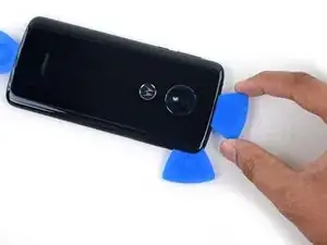
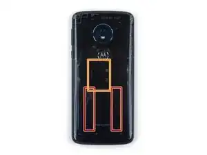
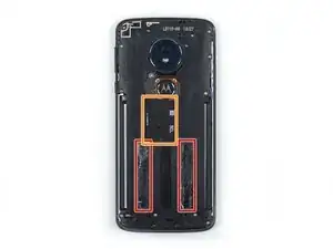
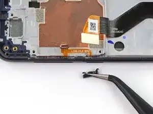
    • There are two strips of adhesive on either side of the lower half of the phone that must be separated to remove the rear glass panel.

    • You will need to release these adhesive strips without damaging the fingerprint sensor cable located in the center of the phone.

  13. jHdhAcjyCmnQkS3C
    jHdhAcjyCmnQkS3C
    rtGlJLGsYGAObMRO
    atyTFnuurjasgRQ5
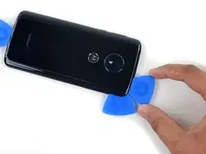
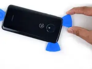
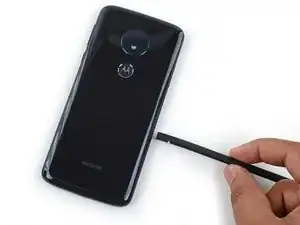
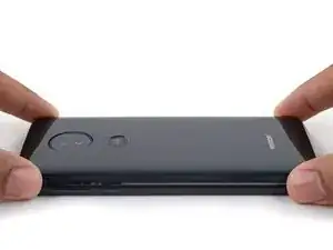
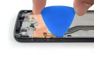
    • Insert the flat end of a spudger into the lower half of the right side of the phone about 2 cm and slide it down the right edge to release the right strip of adhesive.

    • Do not insert the spudger too deep, and pry slowly to prevent damaging the fingerprint sensor cable or cracking the rear glass panel.

  14. SiRxqF65jjFjoivI
    SiRxqF65jjFjoivI
    KJMZVAEkBQXWlI2l
    t2dZYFx5UaJkUmUE
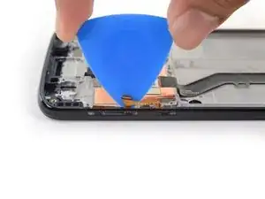
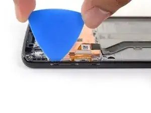
    • Insert a spudger into the lower half of the left side of the phone about 2 cm and slide it down the left edge to release the left strip of adhesive.

    • Do not insert the spudger too deep, and pry slowly to prevent damaging the fingerprint sensor cable or cracking the rear glass panel.

  15. YmrheIDumIXORnmW
    YmrheIDumIXORnmW
    VN5C2tXSPcdVlBcn
    • If the glass remains stuck, re-heat and slice any remaining adhesive repeatedly as needed.

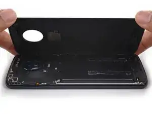
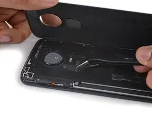
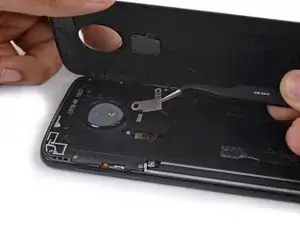
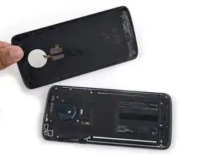
    • Lift the rear glass carefully, making sure it's fully separated from any adhesive.

    • Open the rear glass.

    • Do not completely remove the rear glass panel, as the fingerprint sensor is still connected to the phone via a fragile ribbon cable.

    • During reassembly, pause here to replace the adhesive on the rear glass using a precut adhesive card or high-strength double-sided adhesive tape, such as Tesa 61395.

    • After closing your device back up during reassembly, stack something heavy, like a textbook or two, on top of the device for 30-60 minutes. This ensures a strong adhesive bond.

  16. vSMnSJaMge4ohmcr
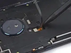
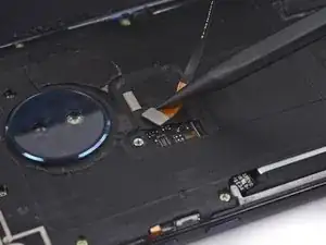
    • Use a Phillips screwdriver to remove the two screws securing the fingerprint sensor cable retention bracket:

    • One silver 1.5 mm screw

    • One gold 3.5 mm screw

  17. erOgWQHHCbKxcmdg
    erOgWQHHCbKxcmdg
    Pm3HoaCgVUQWebaY
    • Use a pair of tweezers to remove the fingerprint sensor cable retention bracket.

  18. fWrrmAX5dpQqIDJM
    fWrrmAX5dpQqIDJM
    MB36QWSIukojp6PG
    • Use the pointed edge of a spudger to disconnect the fingerprint sensor cable.

  19. mnSkGDaAwjObOZcN
    • Remove the rear glass panel.

  20. AviJgSbcSsAPUCCo
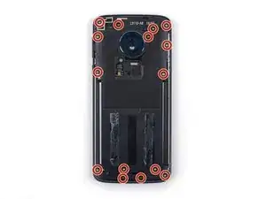
    • Use a Phillips screwdriver to remove the fifteen gold 3.5 mm screws securing the plastic midframe.

    • Some of these screws are covered with stickers. Others are in deep wells and need to be removed with tweezers or pushed out from the other side of the midframe.

    Ein Stückchen Klebeband hilft beim Herausziehen der Schrauben. Auch Krümel vom Kleber können einfach mit Klebestreifen aufgetupft werden.

    Paddler -

  21. ViQohGu5KZbIBfGh
    ViQohGu5KZbIBfGh
    2IB2E2MvvyLhYOiB
    SPLaeVKqKGPGlDEW
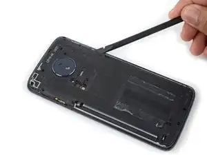
    • Insert a spudger into the notch on the upper right edge of the midframe.

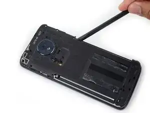
    • Pry the midframe up to release the clips securing it to the device's aluminum frame.

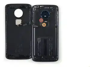
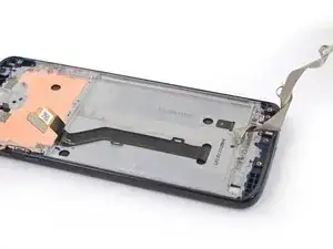
    • Remove the plastic midframe.

  22. hmdYve1A3UkgAFqa
    hmdYve1A3UkgAFqa
    vwqIskuWWjOq5nfk
    • Use a spudger to pry up and disconnect the battery cable.

  23. IyL5SYXZNtHUkEoA
    • Prepare an iOpener and apply it to the middle of the screen, directly behind the battery, for at least two minutes, in order to soften the battery adhesive underneath. Reheat and reapply the iOpener as needed.

    • Be careful not to overheat the battery or display with the iOpener. If you notice the battery swelling at all, immediately remove any heat and let the battery cool down.

    • Alternatively, apply some isopropyl alcohol under each corner of the battery and allow it to penetrate for several minutes to help weaken the adhesive.

  24. P1rrk651UCmiVYAX
    P1rrk651UCmiVYAX
    YNMDUfBNbj3obktX
    nMgWQRNweFaMQ1bZ
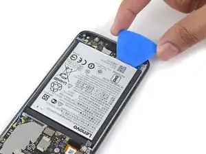
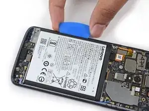
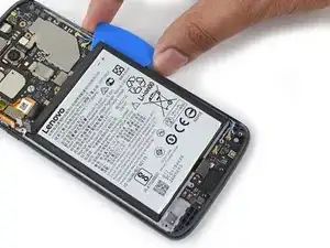
    • Carefully insert an opening pick under the bottom of the battery.

    • You may need to reheat and reapply the iOpener repeatedly to further soften the adhesive. The adhesive is tough and it may take a few tries to get the pick started under the battery. If the battery begins bend out of shape, apply more heat or isopropyl alcohol and pry slower.

    • Try your best not to deform the battery during this process. Soft-shell lithium-ion batteries can leak dangerous chemicals, catch fire, or even explode if damaged. Do not use excessive force or pry at the battery with metal tools.

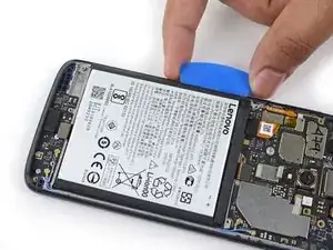
    • Gradually push the pick further under the battery to pry up the bottom edge.

    • Do not insert the pick more that ~1.5 cm past the edge of the battery to avoid damaging the daughterboard and display ribbon cables.

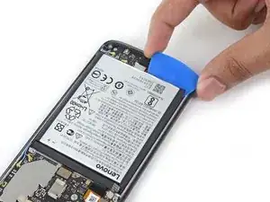
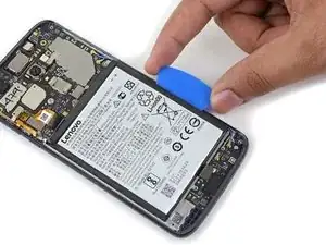
    • Slide the pick all along the bottom edge to release the bottom of the battery.

    Der alte Akku ist wirklich weich. Also langsam und ausgiebig erwärmen. Am unteren Ende des Akkus sind Anfass-Enden, mit denen die beiden Klebestreifen gedehnt und herausgezogen werden können.

    Paddler -

  25. BS6Kl5sNW63dEaGI
    BS6Kl5sNW63dEaGI
    mScHBJpyCiSspegC
    qy3wNddYrpXRUK1S
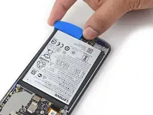
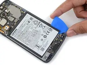
    • Move the pick to the bottom left corner of the battery and begin prying the left edge.

    • If prying becomes difficult, or the battery begins to deform, the adhesive may have cooled down. Reapply a hot iOpener or more isopropyl alcohol to re-soften it.

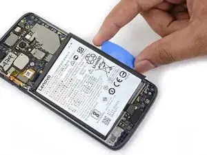
    • Slide the pick all along the left edge to release the adhesive strip under the left side of the battery.

  26. lVjQAyWcfWpsY3oW
    lVjQAyWcfWpsY3oW
    B5bUIF3YA2fWZrM3
    ZilyS1tIII5NNNTU
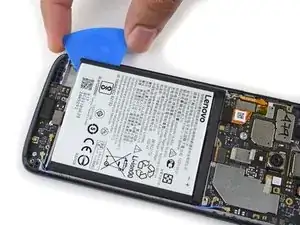
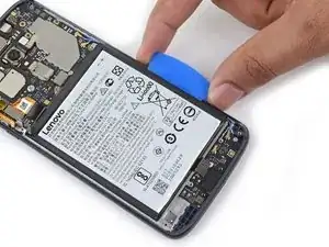
    • Move the pick to the bottom right corner of the battery and begin prying the right edge.

    • If prying becomes difficult, or the battery begins to deform, the adhesive may have cooled down. Reapply a hot iOpener or more isopropyl alcohol to re-soften it.

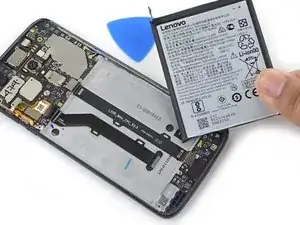
    • Slide the pick all along the right edge to release the adhesive strip under the right side of the battery.

  27. FwLnKpG6Dg2DEQMh
    FwLnKpG6Dg2DEQMh
    q5oLAfcZm3LFlDlk
    5XTjmvTlqZuCFKYh
    • Use the pick to steadily pry the battery up.

    • Remove the battery.

    • Reinstalling a damaged or deformed battery is a safety hazard. Replace it with a new battery.

  28. mExnfRZeyHoIJPIQ
    • Remove the two adhesive strips on either side of the battery well.

    • If you are reusing the screen, during reassembly, clean any residual adhesive in the battery well with isopropyl alcohol. Apply new battery adhesive strips, adhesive from a precut adhesive sheet, or high-strength double-sided tape into the well before pressing the new battery into place.

  29. s5kgCZNKdBoJpxQV
    s5kgCZNKdBoJpxQV
    LmFJx2baqTPTWM4i
    • Use a pair of tweezers to carefully remove the tape covering the camera module connector.

    • It is not necessary to completely remove the tape, just the part covering the connector.

    • Try to not damage the tape so it can be reused during reassembly.

  30. F3wasa1NcMttoKVS
    F3wasa1NcMttoKVS
    MxMW5ZP4NJZK1SFt
    5c2iPsWvqpukui2A
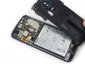
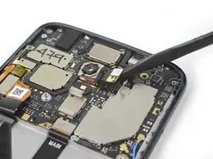
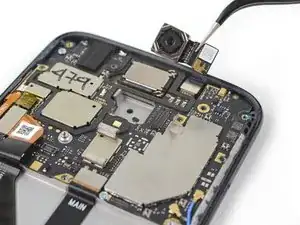
    • Use the flat end of a spudger to pry up the camera module connector and disconnect it.

    • Remove the camera module.

  31. Z1JEmd3svNbDjOpF
    Z1JEmd3svNbDjOpF
    ulthSNFCRHSraoTp
    rixJYjMxXkb6RZcf
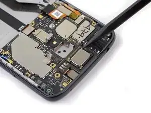
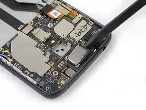
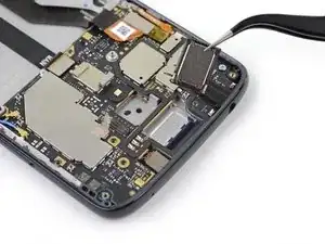
    • Insert the pointed end of a spudger underneath the bottom left corner of the earpiece speaker and pry it up.

    • Remove the earpiece speaker.

  32. Ox6QOMHDqspdeNrB
    Ox6QOMHDqspdeNrB
    gEbqSTGSqmwDmW3W
    • Use a spudger to pry up and disconnect the daughterboard flex cable.

  33. PFacU3XZ6Rq4gmB4
    PFacU3XZ6Rq4gmB4
    To6xwwSbgftWQVk3
    • Use the pointed end of a spudger to pry up and disconnect the black antenna cable.

    • These UFL connectors are fragile. Take care to not damage them when disconnecting or reconnecting.

  34. juiwFhkTBktH2R4J
    juiwFhkTBktH2R4J
    fexCilSQqtGcGJSX
    • Use the pointed end of a spudger to pry up and disconnect the blue antenna cable.

  35. S4m5VSVpvCLHgJVd
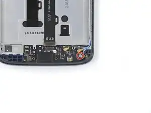
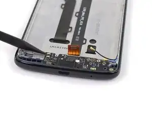
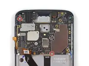
    • Use a Phillips screwdriver to remove the single silver 2 mm screw securing the daughterboard.

  36. lnirNGZgAFRH3lwJ
    lnirNGZgAFRH3lwJ
    d5Ed1JcHDwAfJv5d
    ZEZRfddiCOHRHOig
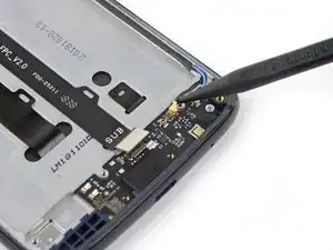
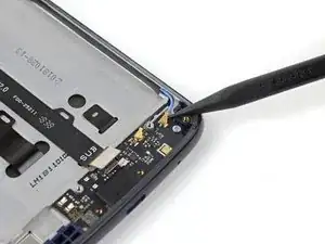
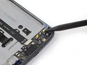
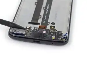
    • Use the pointed end of a spudger to pry up the top left corner of the daughterboard.

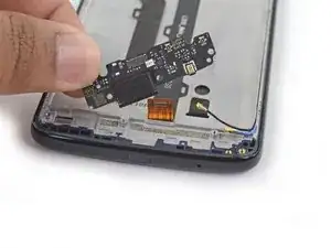
    • Remove the daughterboard.

    • During reassembly, ensure the Micro-USB port gasket is properly seated on to the Micro-USB port. Then, insert the daughterboard gasket-side first, ensuring there are no cables stuck underneath it, and set it into place.

  37. ncZXqCM1eTsxRLF2
    ncZXqCM1eTsxRLF2
    x2N2giuuWVdSGlHx
    • Use a spudger to pry up and disconnect the daughterboard flex cable from the motherboard.

  38. SqPJCNIvVyQJDOdM
    SqPJCNIvVyQJDOdM
    dEBJm2JjS42313rc
    • Use a spudger to pry up and disconnect the display flex cable.

  39. I4stTRuvUJsAIMJt
    I4stTRuvUJsAIMJt
    CNaQk1oyVgwVfiFl
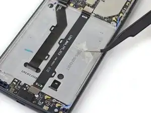
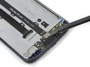
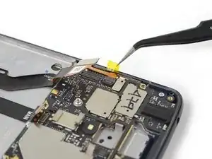
    • Use a pair of tweezers to remove the piece of tape covering the side button flex cable connector.

    • Retain this piece of tape for reassembly.

  40. 6xPV6bR1hnJIlxuE
    6xPV6bR1hnJIlxuE
    fR3FIMbA5bRhx33b
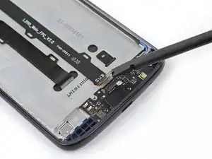
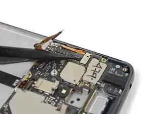
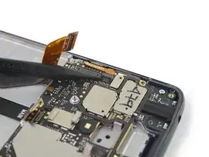
    • Use the pointed end of a spudger to flip up the locking flap on the side button ZIF connector.

  41. EuYyS1pY2HlJX5nj
    EuYyS1pY2HlJX5nj
    fNiNPNMoG5VIROOk
    • Use a pair of tweezers to slide the side button cable out of its socket.

  42. x6JWRHdEM4ohdRs1
    x6JWRHdEM4ohdRs1
    GKDRobMQpQrZIhSB
    • Use the pointed end of a spudger to pry up and disconnect the black antenna cable.

    • These UFL connectors are fragile. Take care to not damage them when disconnecting or reconnecting.

  43. tE5FHPmol6yKoLDD
    tE5FHPmol6yKoLDD
    fdHBfTACEyJYWC1U
    • Use the pointed end of a spudger to pry up and disconnect the blue antenna cable.

  44. VwUxQOmaJm6DSX2p
    • Use a Phillips screwdriver to remove the two silver 2 mm screws securing the motherboard.

  45. XfV5Tx1gQsUmGfQh
    XfV5Tx1gQsUmGfQh
    ZtyUiq5CTTr2aGpe
    bewbrs5BmOBr5GUI
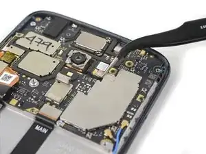
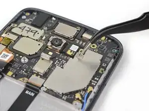
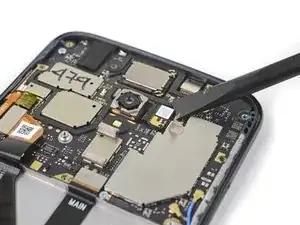
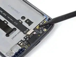
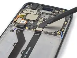
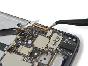
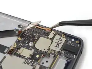
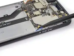
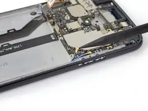
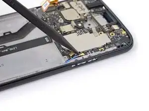
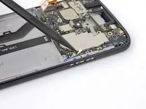
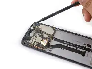
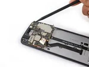
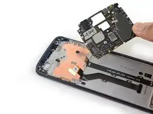
    • Use the pointed edge of a spudger to pry up the top right corner of the motherboard.

    • Remove the motherboard.

    • During reassembly, ensure the headphone jack gasket is properly seated on to the headphone connector. Then, insert the motherboard gasket-side first, ensuring there are no cables stuck underneath it, and set it into place. Ensure the front facing camera is properly seated as well.

  46. RDSH5CgJ4AgVQmnQ
    RDSH5CgJ4AgVQmnQ
    W2I3FWZQfZVkM3RK
    x3o1aHvRBVAEN6tC
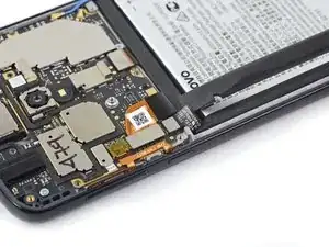
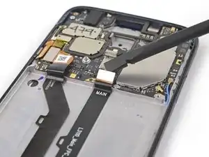
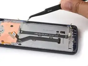
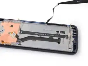
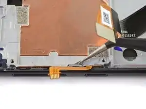
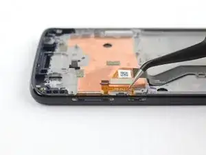
    • Use a pair of tweezers to remove the black strip of tape covering the antenna cables.

    • Retain this piece of tape for reassembly.

  47. VpSlBRhco2h3KArv
    VpSlBRhco2h3KArv
    AHmxsTcYZsduYhRb
    DSBlPefT4h3B5Pcw
    • Remove the two antenna cables from their channel in the side of the battery well.

    • The coaxial cables are fragile and can be damaged if not removed with care, especially if with metal tools.

    • During reassembly, insert the black antenna cable on the bottom of this channel to promote clean cable management.

  48. ZFlj4RIGq3HDGb5U
    ZFlj4RIGq3HDGb5U
    rSVEy4H1BoM3IZrR
    QsU56FNUHwFTQpUD
    • Peel up the daughterboard flex cable and remove it.

    • This ribbon cable is fragile; take care to not damage it if removing with metal tools.

  49. sCFS1oWWpYYnrMuA
    sCFS1oWWpYYnrMuA
    2aRMsWmYTvHblL1Z
    oG3T1bv5QHoWCxAG
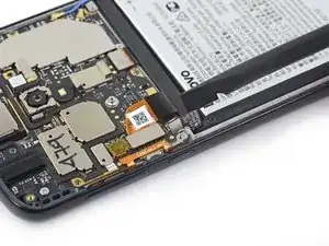
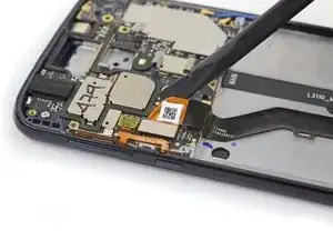
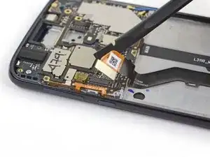
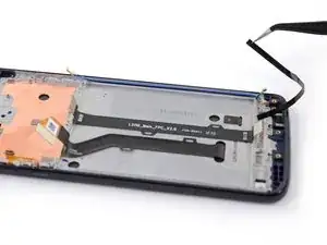
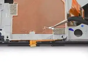
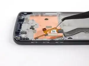
    • Use a pair of tweezers to remove the daughterboard cable adhesive.

    • Try to keep this piece of tape as intact as possible for reassembly.

  50. OT2M1yQt2Wq1EGQY
    OT2M1yQt2Wq1EGQY
    qUKXOgdwmenKVacf
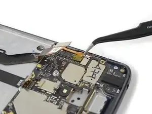
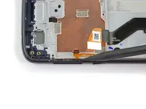
    • Use a pair of tweezers to remove the small silver side button retention bracket from the left side of the device.

  51. xM1DjH3ZAxOTAbWX
    xM1DjH3ZAxOTAbWX
    iQHs4bZERRmPZhoq
    ROmQB3DYFYTwrNtI
    • Use the point of a spudger to push against the back of the volume button, behind its lower end, so that the lower end of the button slides out of the phone first.

    • Use tweezers to gently remove the volume button, by pulling it from its lower end.

    • When reinstalling the volume button, insert the upper end first, then the rest of the button.

  52. tVeJgpbJS6LXSPpA
    tVeJgpbJS6LXSPpA
    NPPAtrT5Fja5Tciu
    GMKqwSBqUdsIDXvo
    • Use the point of a spudger to push against the back of the power button, behind its upper end, so that the upper end of the button slides out of the phone first.

    • Use tweezers to gently remove the power button, by pulling it from its upper end.

    • When reinstalling the power button, insert the lower end first, then the rest of the button.

  53. 61SIxU6XcdZAXtaw
    61SIxU6XcdZAXtaw
    1EaHh1EgMjxrsRrX
    G5JwRPKjVCPECWk2
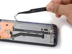
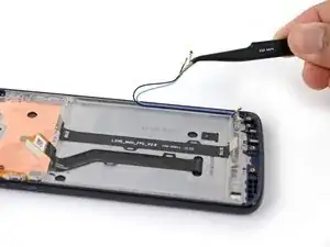
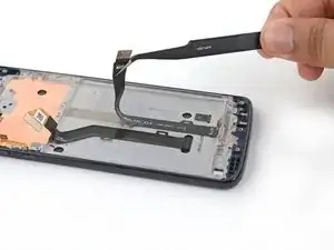
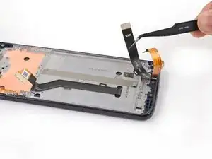
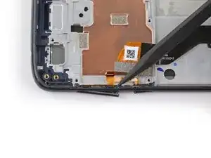
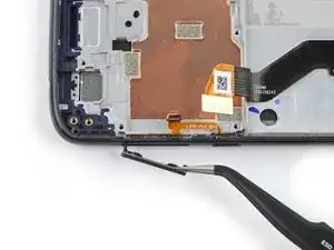
    • Insert an opening pick between the power and volume button circuit board and the frame.

    • Slide the pick behind the circuit board, across the whole board, to separate it from the adhesive securing it to the frame.

    • If it's difficult to slide the pick behind the circuit board, try heating the circuit board to soften its adhesive.

  54. D2VGeRHhavMO5Q1e
    D2VGeRHhavMO5Q1e
    ivMkqhCJMEh1w6Xx
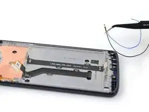
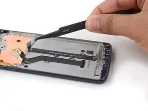
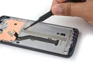
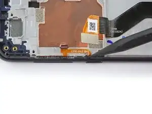
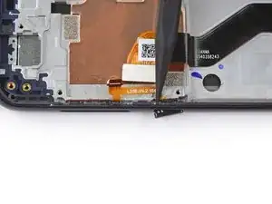
    • Use tweezers to carefully pull the volume and power button circuit board out of its slot. If it's difficult to remove, make sure you've sliced through all its adhesive.

  55. TD5ATQ314K1OQFdu
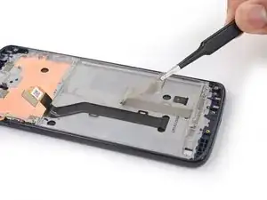
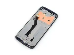
    • Only the screen assembly remains.

    • Compare your new replacement part to the original part—you may need to transfer additional components or remove adhesive backings from the new part before installing.

Conclusion

To reassemble your device, follow the above steps in reverse order.

Take your e-waste to an R2 or e-Stewards certified recycler.

For optimal performance, after completing this guide, calibrate your newly installed battery.

Repair didn’t go as planned? Try some basic troubleshooting, or ask our Moto G6 Play Answers Community for help.

Tarun Thiruma

Member since: 20/11/19

32499 Reputation

0 comments