Introduction
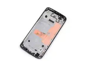
Use this guide to replace the screen on your Moto G6, including the midframe which is glued to the display.
Make sure your replacement part includes both the display and the midframe—this guide does not cover separating the display from the midframe.
This procedure involves removing the battery, which may be damaged during the removal process. We strongly advise you do not reuse the battery as doing so may pose a safety hazard. Replace it with a new battery.
-
-
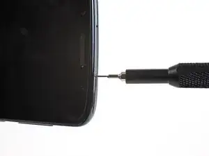
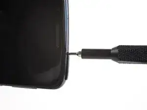
Insert a paperclip or SIM card eject tool into the small hole in the SIM card tray on the right side of the top edge of the phone.
-
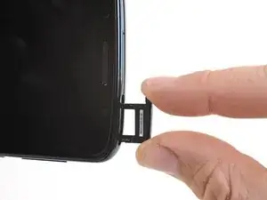
Press the tool into the hole to eject the tray.
-
-
-
If possible, drain the battery before disassembly. When the battery is charged, there's an increased risk of a dangerous thermal event if the battery is overheated or damaged during repairs.
-
Prepare an iOpener and heat the back of the phone along its bottom edge for about two minutes, or until it's slightly too hot to touch. This will help soften the adhesive securing the rear glass.
-
-
-
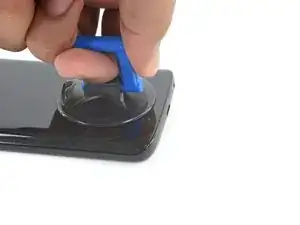
Apply a suction cup to the bottom edge of the rear glass.
-
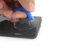
Pull up on the suction cup with firm, constant pressure to create a slight gap between the rear glass and the frame.
-
If you have trouble, apply more heat to further soften the adhesive, and try again. The adhesive cools quickly, so you may need to heat it repeatedly.
-
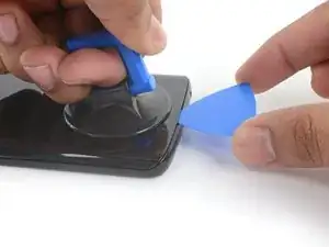
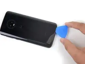
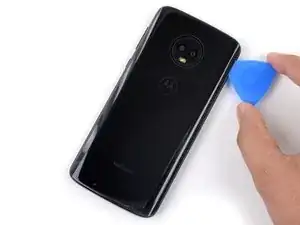
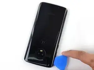
Insert an opening pick into the gap you created under the rear glass.
-
-
-
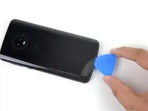
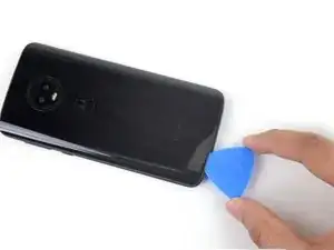
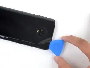
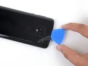
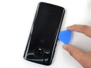
Slide the pick all along the bottom edge of the phone to slice through the adhesive securing the rear glass.
-
-
-
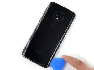
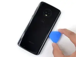
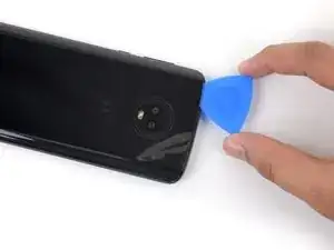
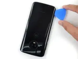
Slide the pick all along the top edge of the phone to slice through the adhesive securing the rear glass.
-
-
-
If the glass remains stuck, re-heat and slice the adhesive repeatedly as needed.
-
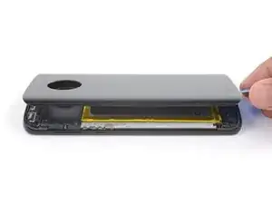
Lift the rear glass carefully, making sure it's fully separated from any adhesive.
-
Remove the rear glass.
-
-
-
Use a pair of tweezers to carefully peel up the black tape covering the battery.
-
Remove the tape.
-
-
-
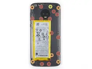
Use a Phillips driver to remove seventeen screws securing the plastic cover:
-
Eleven grey 3 mm-long screws
-
Five black 2.5 mm-long screws
-
One silver 3.5 mm-long screw
-
-
-
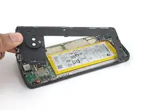
Insert the pointed end of a spudger into the notch at the top left edge of the plastic cover.
-
Pry up with the spudger to lift the upper edge of the cover and release the clips holding the cover down.
-
Remove the plastic cover.
-
-
-
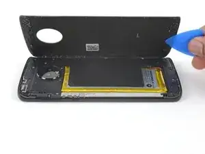
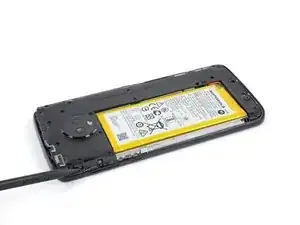
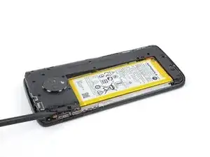
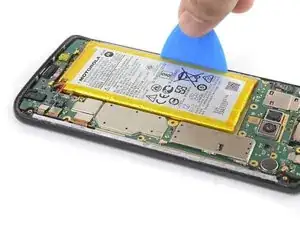
Prepare an iOpener and apply it to the right half of the screen for at least two minutes, in order to soften the battery adhesive underneath. Reheat and reapply the iOpener as needed.
-
-
-
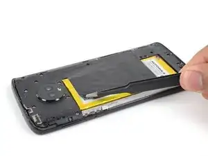
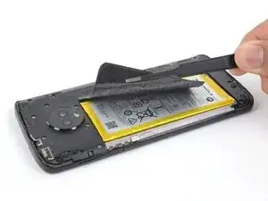
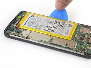
Use an opening pick to steadily pry the battery up, starting from the outer edge of the battery.
-
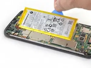
Remove the battery.
-
-
-
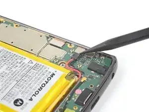
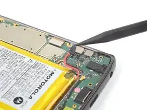
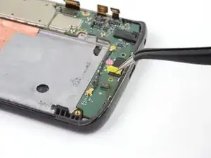
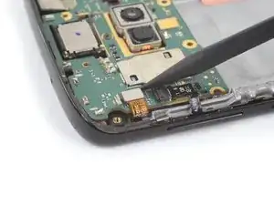
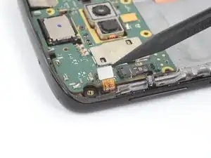
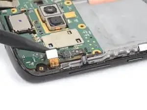
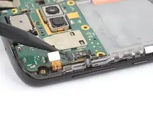
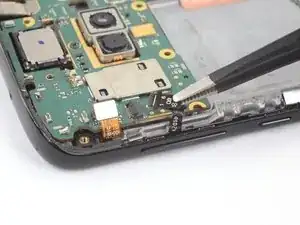
Use the pointed edge of a spudger to pry up and disconnect the three ribbon cables on the bottom right edge of the motherboard.
-
-
-
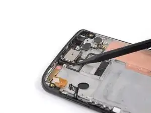
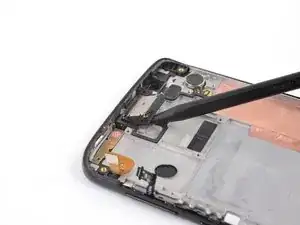
Use the pointed end of a spudger to pry up and disconnect the front-facing sensor cable on the top left edge of the motherboard.
-
-
-
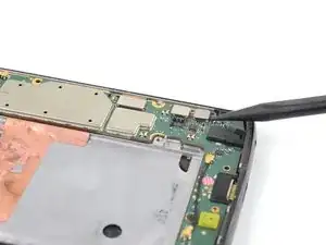
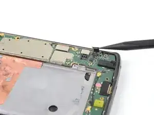
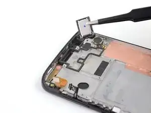
Use the pointed end of a spudger to pry up the locking tab on the button cable's ZIF connector.
-
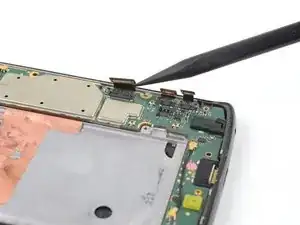
Use a pair of tweezers to slide the button cable out of its socket.
-
-
-
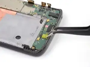
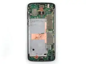
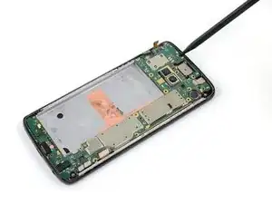
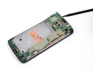
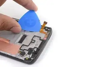
Use the pointed end of a spudger pry up the top edge of the motherboard, while keeping it clear of any cables or connectors.
-
Slide the motherboard toward the top edge, until it is free, and remove it.
-
-
-
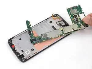
Use the pointed end of a spudger to pry up one corner of the earpiece speaker.
-
Continue lifting the speaker until it is completely separated from its adhesive.
-
Remove the earpiece speaker.
-
-
-
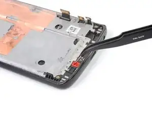
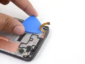
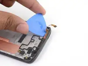
Gently slide an opening pick under the front-facing sensor cable to slice through the adhesive holding it to the midframe.
-
Use the opening pick to carefully pry the front-facing sensor array away from the midframe.
-
-
-
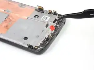
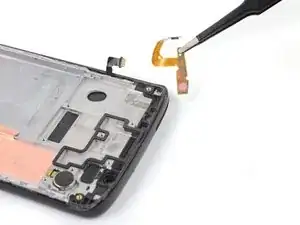
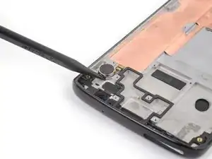
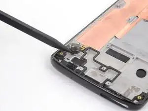
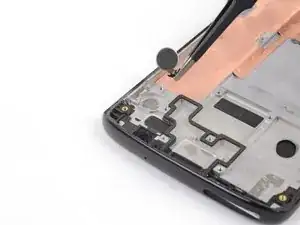
Use the point of a spudger to pry the vibrator motor and its cable up from the adhesive securing them to the midframe.
-
Remove the vibrator motor.
-
-
-
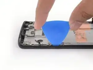
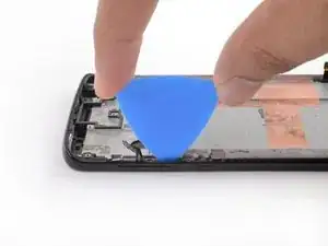
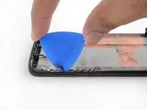
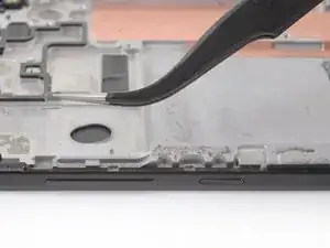
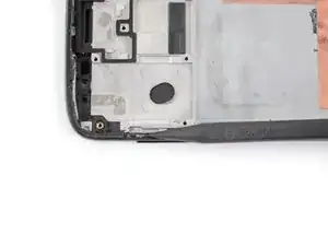
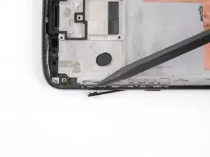
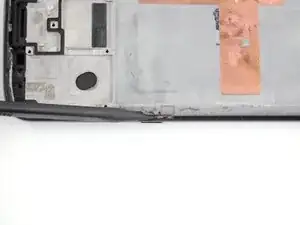
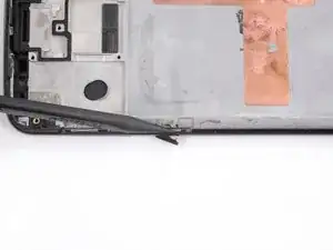
Insert an opening pick between the power and volume button circuit board and the frame.
-
Slide the pick behind the circuit board, across the whole board, to separate it from the adhesive securing it to the frame.
-
-
-
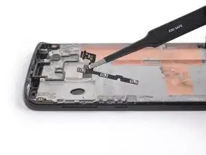
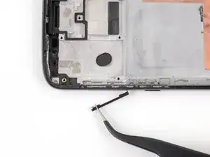
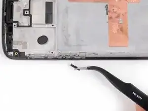
Use tweezers to carefully pull the volume and power button circuit board out of its slot. If it's difficult to remove, make sure you've sliced through all its adhesive.
-
-
-
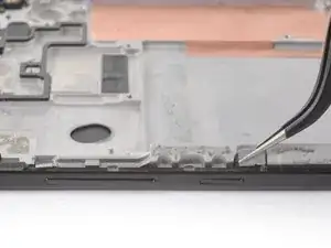
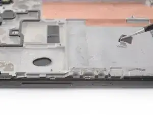
Use tweezers to lift the two silver retention brackets flanking either end of the volume and power buttons straight up and remove them from the phone.
-
-
-
Use the point of a spudger to push against the back of the volume button, behind its upper end, so that the upper end of the button slides out of the phone.
-
Use tweezers to gently remove the volume button, pulling up from the upper end.
-
-
-
Use the point of a spudger to push against the back of the power button, behind its lower end, so that the lower end of the button slides out of the phone.
-
Use tweezers to gently remove the power button, pulling down from the lower end.
-
-
-
Only the screen assembly remains.
-
Compare your new replacement part to the original part—you may need to transfer additional components or remove adhesive backings from the new part before installing.
-


To reassemble your device, follow the above steps in reverse order.
Take your e-waste to an R2 or e-Stewards certified recycler.
For optimal performance, after completing this guide, calibrate your newly installed battery.
Repair didn’t go as planned? Try some basic troubleshooting, or ask our Motorola Moto G6 Answers community for help.

8 comments
hello does anyone knows what is the part number of the housing/bracket or gasket (not sure how to call it) that holds the powerr and volume bottom into place on moto g6play?
1nonly -
Nice instructions. I suggest adding that around step 24 or 25 removal of the rubber gasket/boot around the selfie camera be included. I didn’t see this anywhere in the instructions but found the part rolling around my table shortly after these steps. Also, as a general suggestion, and ice cube tray make organizing all the screws and little parts pretty easy.
Thanks for identifying the selfie gasket.
This can be done more quickly and easier by removing the front glass too. Then unplugging the 3 cables from the motherboard, and feeding your new screen cables through the front into the back.
The sim card eject tool has snapped inside the ejector hole,is there another way to get the sim card out ?.
Amanda Ashley -
You can try to carefully push the snapped pin with another ejector tool to eject the tray. Otherwise, lightly tap the phone edge to try to get the snapped pin out.
Arthur Shi -