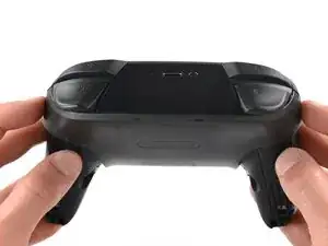
Introduction

Use this guide to replace the joystick control modules on your Nintendo Switch Controller. To complete this project, you must be able to solder. Care should be taken in the removal of the plastic body pieces and the internal circuit board of the device to avoid damage that could render the device inoperable. This project also involves the removal of a lithium-ion battery, and if swollen, be sure to take appropriate precautions.

  1. iaKRfcPV2HNC5yUK
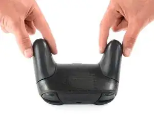
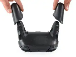
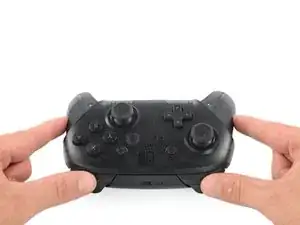
    • Flip the controller over so the model stickers face the ceiling.

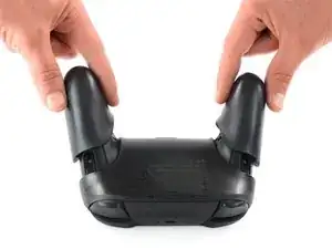
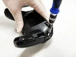
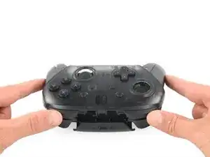
    • Use a JIS #00 screwdriver to remove the two black 8.4 mm screws that secure the handles, located at the ends of the handles.

    Be carefull, these screws are super easy to strip even with the right tools.

    Lukas Eberharter -

    I tried editing these instructions after I had trouble with stripping screws, but it doesn't seem to take. The issue is that these are JIS and not Phillips screws. They are VERY similar looking but a Phillips head screwdriver will strip the screws.

    Isaac Webb -

    I tried using a Philips #00 screwdriver but it didn’t work

    vincent ingrassia -

  2. pFHHOlTyvlQ43DOC
    pFHHOlTyvlQ43DOC
    KCE54LsPyGnuWTkW
    UNYZtREEKVfHallZ
    • Carefully remove the handle covers by pulling them away from the main body.

  3. 3OnYDcOU1gVR2fEG
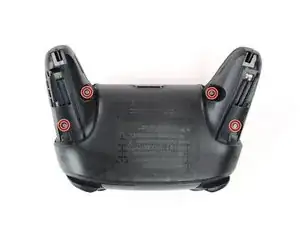
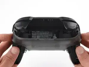
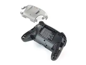
    • Use a JIS #00 screwdriver to remove the four silver 6.8 mm screws that secure the clear back plastic cover.

  4. Zb3Ool4Evh63KKVd
    Zb3Ool4Evh63KKVd
    E4qBEgOibCQbXlIJ
    jihxJQfDSqclVJnF
    • Carefully pry away the clear plastic cover using your fingernail.

  5. p4bHAkTpIvuBFIfc
    • Remove the clear plastic cover.

  6. yUbMYllrTC6sSOGL
    yUbMYllrTC6sSOGL
    6pxWhyQpxoXGbs22
    vEF6WXIGCHUebiZO
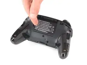
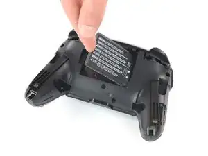
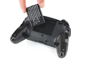
    • Remove the lithium-ion battery by using a fingernail or plastic opening tool to pry it up on the left side.

    • Only a small amount of force is needed.

  7. 41hYi1SofYMKVF4B
    41hYi1SofYMKVF4B
    IhtOVVcrnx5IBHgJ
    WJ4LvGQlKLhlREns
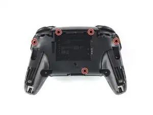
    • Use a Phillips screwdriver to remove the five 5mm-long screws from the back of the controller.

    the 2 screws up at the top are unreachable with the standard fixit kit just a heads up

    drew -

    Seconded. the screws are located too deep below the plastic slot, and the bit holding bulge is too wide for the small aperture (similarly with the flexible extension). the bit length is too shallow to reach.

    An alternative driver with a much narrower & longer shaft is required, which will likely not come with interchangeable bits.

    Douglas Selby -

    I would say it is possible to reach the top left screw, just not the top right - there is a gap in the top left that allows you to slightly bend the standard driver outward to turn it while still making adequate contact.

    El_Mechacontext -

    An update: I was actually able to remove the top right one in a really hacky way - inserting the Phillips #0 bit into the #4 hex bit, and then using that in the standard driver. This added just enough length to successfully reach and make full contact with the screw!

    El_Mechacontext -

    Using the #4 hex bit as an extension was the exact "hack" I needed to get rid of the drift finally. Thank you. You're a lifesaver.

    Das #4 Hex Bit als Verlängerung für das Kreuzschlitz Bit zu nutzen ist zwar etwas eng, aber es erspart einem wirklich einen zusätzlichen Schraubendreher.

    Techn0magier -

  8. PnIrdtdY4KCyxuKK
    PnIrdtdY4KCyxuKK
    ZBKtxPXnhQuBTaDN
    OZcevYGCPPARFaRx
    • Delicately take off the plastic cover from the controller.

    • Do not completely remove the front cover just yet, as it is still attached to the motherboard via a white ribbon cable.

    Didn't realize there is adhesive holding the front cover onto the unit. It's located inside of the handles. Just a bit of force there helped, just be careful of the cable.

    Roger Perez -

  9. NpVhXDsYSWmW4tBT
    NpVhXDsYSWmW4tBT
    QXe1DlCMuCXbrveX
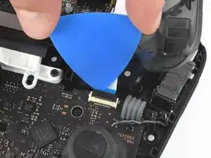
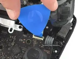
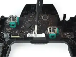
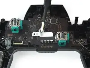
    • Use the tip of an opening pick to open the black flap of the ZIF connector by pushing it upwards.

  10. 3qj6VtFJtKAHHm6I
    3qj6VtFJtKAHHm6I
    YJvaLXngDhvHF1Gr
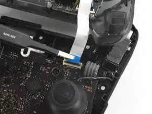
    • Use your fingers or a pair of blunt nose tweezers to disconnect the interconnect cable from its connector.

  11. OpC2vBHXBB35uAQ4
    • Remove the front case.

  12. fmhalkYPurcsCRYL
    fmhalkYPurcsCRYL
    elaYKLLtkDSyGABw
    rEIOPXEXhFo3sEO1
    • With light force pull the two joystick caps off of the controller.

  13. dTuT4xSHUxiNECZU
    • Use a Philipps screwdriver to remove the four 5 mm-long screws securing the motherboard.

  14. BMiSYbhVXs6Z3Y6U
    BMiSYbhVXs6Z3Y6U
    sZdbNwAjKaEEAa2e
    SM4NBN5cFyWiAWXF
    • Use your fingernail or a pair of tweezers to pry the LED light away from its slot.

    • Set aside the LED light with its corresponding screw for reassembly.

    You are not removing the 4 LEDs here, they are soldered on the board. You are only removing the light transporting plastic piece.

    Uncle BenZ -

  15. ZhSJFHfoB5uIhdwh
    ZhSJFHfoB5uIhdwh
    FocRPjIyriVEQ5Y6
    BgjPKaESfuRXL5Bj
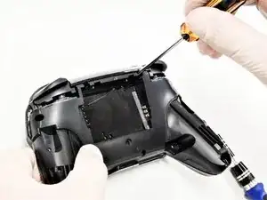
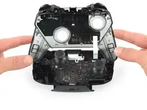
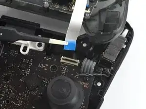
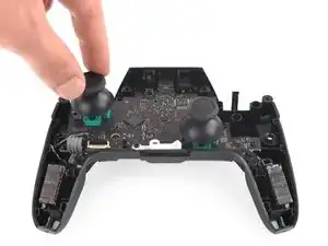
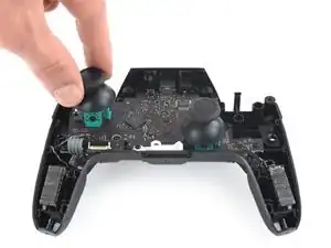
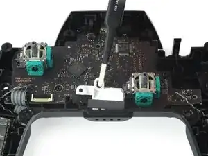
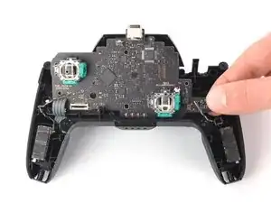
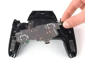
    • Loosen the circuit board off the chassis by gently pulling at the bottom right corner.

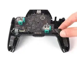
    • Lift the circuit board up to expose its backside.

    • Avoid using too much force when lifting the circuit board to prevent damaging the wires.

  16. uia1EpJV3nO4epIX
    uia1EpJV3nO4epIX
    UGJsFktqRYicBsPH
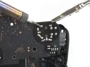
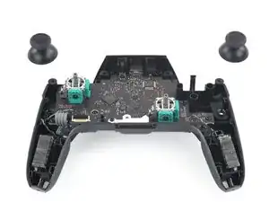
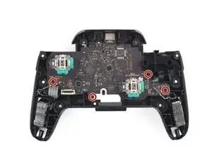
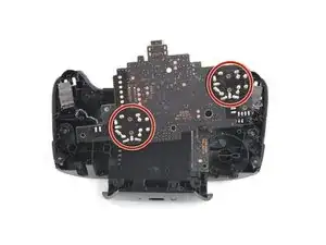
    • Turn to the backside of the circuit board for clear access to the solder joints.

    • Desolder all of the outlined solder joints.

    • Remove the joystick module from the circuit board.

    • Refer to the following solder guide if necessary: How To Solder and Desolder Connections

    Bonjour,pour dessouder les joysticks, qu’avez-vous utilisez comme outil: de la tresse ou une pompe à dessouder ?

    Par avance merci.

    Patrick

    le hellegouarch -

    J’ai utilisé une pompe, avec de bons résultats

    Brian -

    The most difficult part of this was desoldering. I used no-clean soldering braid and the original solder did not wick up. I heated each solder pad and added just a bit of 60/40 tin/lead solder. After that the braid worked much better and all solder wicked up to the braid allowing me to remove the component.

    paulshopping -

    I used this tutorial to replace one broken joystick after it took s heavy hit but now both of my joysticks drift and when I tried to calibrate them they looked to be moving on there own please help

    Jeroen Zomer -

Conclusion

To reassemble your device, follow these instructions in reverse order.

Daniel Tagalog

Member since: 10/10/19

1212 Reputation

16 comments

I managed to replace mine with much difficulty with the soldering but the stick does not seem to turn fully anymore, both with the replacement and the original. For reference, when I go to test it, it no longer registers as reaching the outer circle when pressed all the way down. Similarly when I go to calibrate it, it only reaches up til about the 2nd outer circle, not enough to actually trigger the green arrow. Since this seems to occur on both the replacement and original stick now, I’m guessing this must be some issue that arose while I was struggling with the desoldering process. Anybody have any ideas what might be causing my issue? Have I just damaged it beyond repair?

Tyler -

Without pictures it is impossible to tell, but there is the possibility that you strips the metal connection on the solder point. This is fixable by “bridging” the connection. You will want to find schematics of the wiring for the PCB and then solder the wire over to the next connection.

As a side note, I should mention that I have never tried this on a controller of any sort and that I have only used this method on keyboards with single wire connections. It is possible that the connection in a controller PCB have more going on and that this technique will not work.

Gavin A -

I have the same problem, I buy 2 joystick module from iFixit and the two gave me the same issue, the joystick module don't reach the green arrow.

I can't calibrate because of that issue.

Any ideas?

Piero Grasso -

I have also had the same issue with replacement, only reaches roughly 75%. I contacted ifixit and they sent me a replacement thinking it might be a faulty pot, I installed the new stick and have the same issue. Maybe different years used different resistance.

marcos aguilera -

Excellent guide. Thank you. Saved me from having to buy a $70 controller.

One comment though, all the screws are actually Phillips #0 except for the grip screws, which are Phillips #00

Brian -

I managed to repair a drifting stick input without any soldering by just replacing the potentiometer in the stick module. You can pry open the housing on the sides, swap it out (make sure it’s the right orientation), and snap it back into place. Potentiometers for Dualshock 4 analog sticks worked for me—apparently these parts are industry standard. Doing this from now on for all my drifty sticks.

Scott Baker -

Hi Scott —

.

So, first off, thanks for the tip! Now, I realize I may be asking a bit much of you here, but, is there any chance you could post/take/fwd any pics of the (sub)procedure you describe? It’d be really helpful to have a reference like that before I tear into a functioning joystick — even if it has a sporadic (though no less infuriating for that) issue.

.

If that’s not feasible, then perhaps you know of and can post a link to a decent guide for doing so on any of the platforms that use these (apparently standard) items?

.

Thanks in advance for any help on this! :oD

anatinus -

I would like to try it your way. Do you have any pictures or something like it. Maybe a video?

André Schenkels -

Do you know how to correctly reassemble the grey piece in the picture?

First thought was something had snapped but after popping off the same piece from the other (working) thumbstick they seem to be identical and neither the part nor the socket seems damaged. I also can’t see any evidence of glue.

The problem is I can’t get the part to clip back into place - it is supposed to sit flush and taught without any movement when the stick is rotated. But no matter how I reapply it I can’t clip it into place.

https://i.imgur.com/mFOQEUy.jpg

Casey -

After doing this. I lost charging capabilities and the capability to even plug it into a PC. Any advice will be beneficial.

Jose Godoi -

I think the grip screws are JIS #00 which would make sense since this is made in Japan.

jorach -

After replacing my analog with one from iFixIt I am only getting about half range on my analog and cannot complete recalibration. I tried 2 analogs from iFixIt with the same issue. I replaced with the original and have full range again

Peter Roach -

I destroyed some of the wiring, but measured connections on the other stick, and used a thin wire to re-wire the broken connection from top to bottom. Works great, even could calibrate it without issues. Unfortunately I broke the thick wires soldering that connects the battery, I’ll need some more delicate equipment to fix that one, until then it works fine when connected to power with cable.

Thraex Aquator -

I have a broken joystick cap, can I just replace it and stop at step 12?

Thank you

Daniel Cardenas -

Is this verified to be working with the replacement part from ifixit? I ordered 2 but don't want to do all the solder work if ppl are only getting 75% range of motion from the non oem parts

ALAN MITCHELL -

For anyone having problems with reduced stick movement, I ran into the same issue but was able to calibrate the stick in the Switch settings by being persistent and repeatedly trying to give the Switch the calibration input it wanted. I sometimes took short breaks in between inputs, not sure if that mattered. The rotation took the longest, maybe two minutes but eventually it completed and now my left stick is as precise as the right stick which I didn't touch. I hope this helps anyone else!

Luna -