
Introduction
Follow this guide to replace the screen and battery assembly on your Samsung Galaxy S20+ with a genuine Samsung part.
This guide is written for the genuine Samsung screen and battery assembly. The assembly consists of the screen, battery, and frame together in one part. Be sure you have the right part before you begin the repair.
Before you begin, refer to the Samsung Self-Repair document for safety information.
If your battery is swollen, take appropriate precautions. Before disassembling your device, completely discharge the battery. This reduces the risk of a dangerous thermal event if the battery is accidentally damaged during the repair.
Note: Retaining water resistance after the repair will depend on how well you reapply the adhesive, but your device will lose its IP (Ingress Protection) rating.
Some images in this guide may show minor discontinuities. They should not affect the overall guide procedure.
-
-
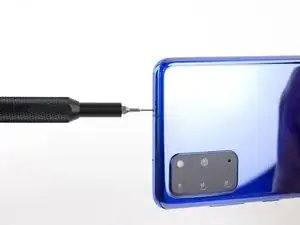
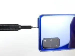
Insert a SIM card eject tool, bit, or a straightened paperclip into the hole on the SIM tray, located at the top edge of the phone next to the plastic antenna band.
-
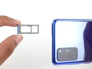
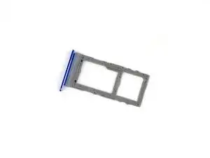
Press in firmly to eject the tray.
-
-
-
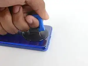
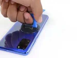
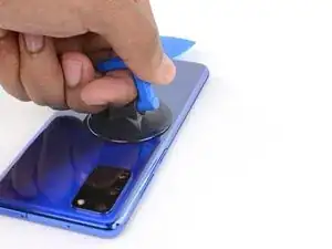
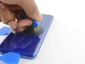
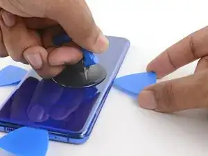
Apply a suction cup to the back of the phone, as close to the center of the bottom edge as possible.
-
Pull on the suction cup with strong, steady force to create a gap between the back cover and the frame.
-
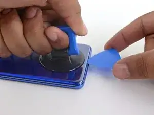
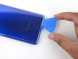
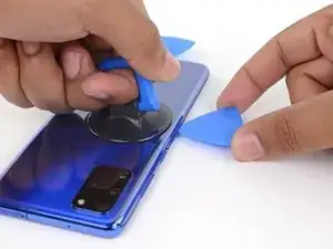
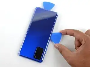
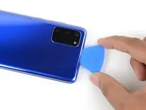
Insert the point of an opening pick into the gap.
-
-
-
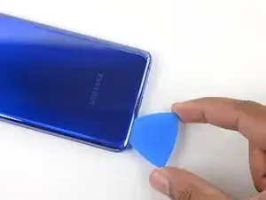
Slide the pick back and forth along the bottom edge to slice through the adhesive.
-
Leave your opening pick in the seam to prevent the adhesive from resealing.
-
-
-
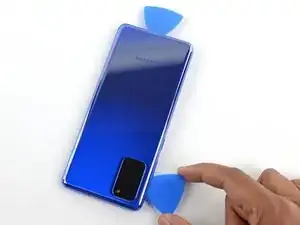
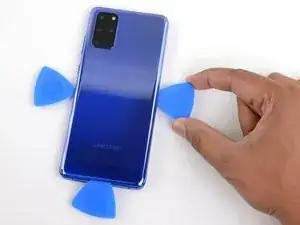
Apply a suction cup to the back of the phone, as close to the center of the left edge as possible.
-
Pull on the suction cup with strong, steady force to create a gap between the back cover and the frame.
-
Insert the point of an opening pick into the gap.
-
You can try also applying a few drops of high concentration (over 90%) isopropyl alcohol into the seam to help loosen the adhesive.
-
-
-
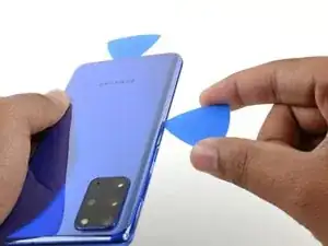
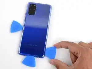
Once the pick is underneath the glass's edge, tilt it downward and insert it further to fully separate the back cover's adhesive.
-
-
-
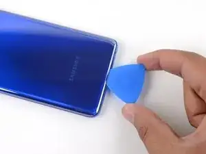
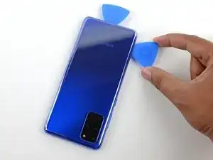
Slide the pick all along the left edge of the phone to separate the back cover's adhesive.
-
Leave your pick under the left edge of the glass to prevent the adhesive from resealing.
-
-
-
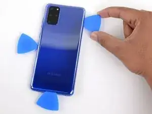
Apply a suction cup to the back of the phone, as close to the center of the right edge as possible.
-
Pull on the suction cup with strong, steady force to create a gap between the back cover and the frame.
-
Insert the point of an opening pick into the gap.
-
-
-
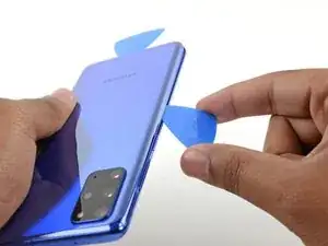
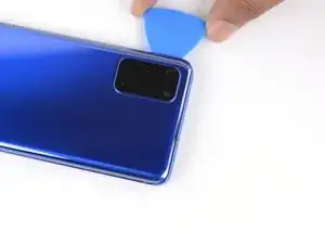
Slide the pick all along the right edge of the phone to separate the back cover's adhesive.
-
Leave your pick under the right edge of the glass near the top of the device to prevent the adhesive from resealing.
-
-
-
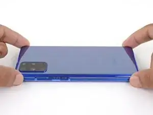
Gradually slide the pick from the right edge of the device around the top right corner.
-
Continue slicing along the top edge all the way around to the left edge to fully separate the back cover adhesive.
-
-
-
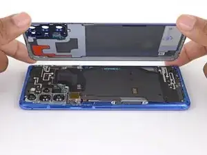
Lift the back cover slowly. Use opening picks to slice any remaining adhesive.
-
Remove the back cover.
-
This is a good point to power on your phone and test all functions before sealing it up. Be sure to power your phone back down completely before you continue working.
-
Remove any adhesive chunks with a pair of tweezers or your fingers. Apply heat if you're having trouble separating the adhesive.
-
If you're using Samsung custom-cut adhesives, follow this guide.
-
If you're using double-sided tape, follow this guide.
-
-
-
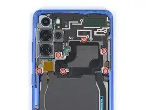
Use a Phillips #00 screwdriver to remove the six 4 mm-long screws securing the motherboard bracket.
-
-
-
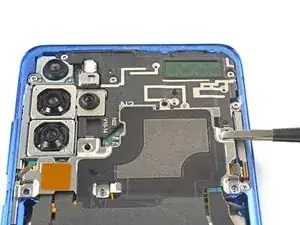
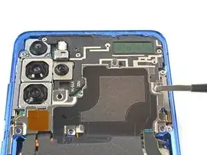
Use a pair of tweezers to gently pull up and unclip the motherboard bracket from the plastic midframe.
-
-
-
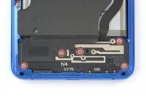
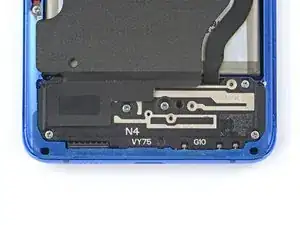
Use a Phillips #00 screwdriver to remove the five 4 mm-long screws securing the loudspeaker and lower midframe.
-
-
-
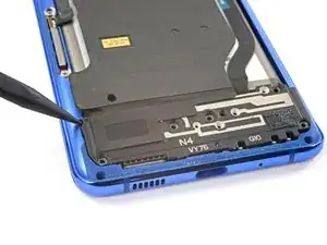
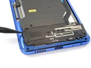
Insert the point of a spudger into the notch in the top left corner of the midframe and pry up to release the clips holding it in place.
-
Remove the loudspeaker and lower midframe.
-
-
-
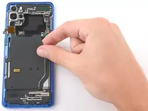
Use a pair of blunt-nose tweezers to gently peel the wireless charging coil away from the device.
-
Remove the wireless charging coil.
-
-
-
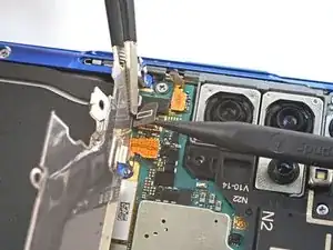
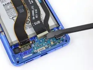
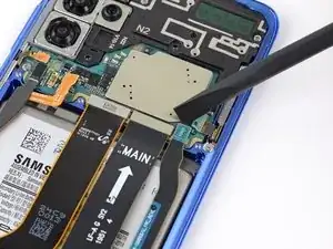
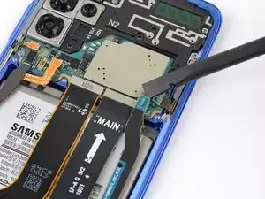
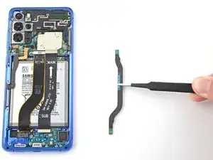
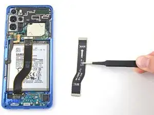
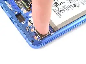
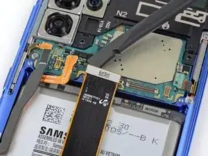
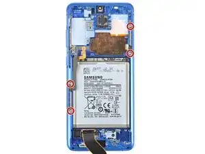
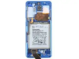
Use a spudger to pry up and disconnect the primary and secondary flex cables from the daughterboard near the bottom of the device.
-
-
-
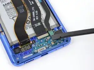
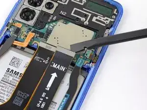
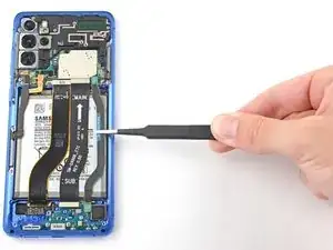
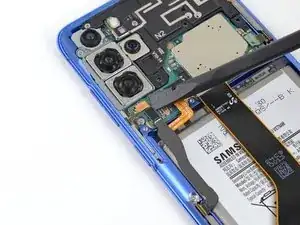
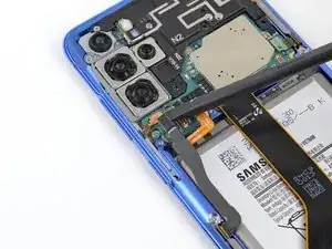
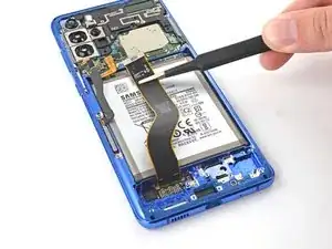
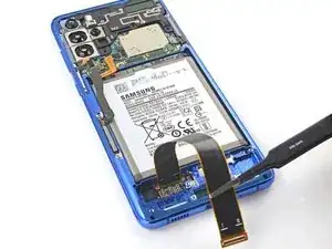
Use a spudger to pry up and disconnect the primary and secondary flex cables from the motherboard.
-
-
-
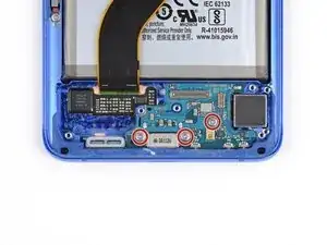
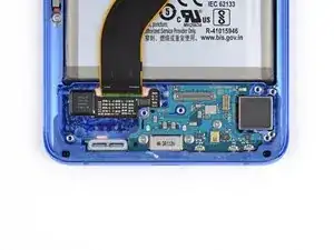
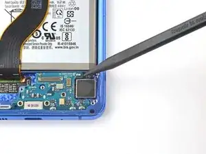
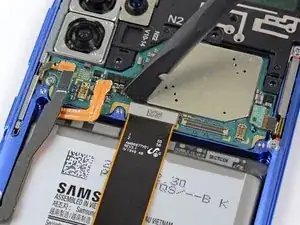
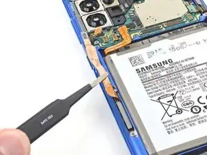
Use a Phillips #00 screwdriver to remove the three 3.4 mm-long screws securing the USB-C port and daughterboard.
-
-
-
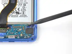
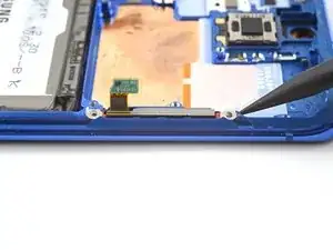
Insert the pointed end of a spudger under the left edge of the daughterboard and pry up to release it from its recess.
-
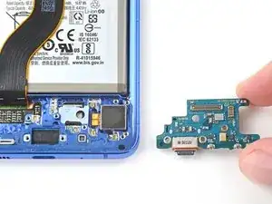
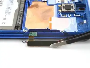
Use a pair of blunt-nose tweezers to pull the daughterboard up and away from the bottom of the device and remove it.
-
-
-
Insert the tip of a spudger between the frame and the notch in the vibrator's edge, close to the bottom edge of the device.
-
Pry up with the spudger to separate the vibrator from the frame.
-
Remove the vibrator.
-
-
-
Peel off the vibrator adhesive from its liner and apply the sticky end to the bottom of the vibrator.
-
Use tweezers, or your fingers, to pull up on the white liner to expose the top layer of adhesive.
-
Insert the vibrator and apply pressure to adhere it to the frame.
-
-
-
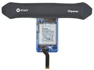
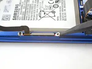
Gently peel up and bend the display and left 5G mmWave antenna flex cables out of the way of the motherboard and battery.
-
-
-
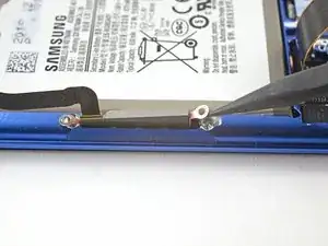
Use a Phillips #00 screwdriver to remove the three 4 mm-long screws securing the upper midframe.
-
If you're reassembling with the Samsung Self-Repair kit, be sure to replace the screws with new ones labeled #3373.
-
-
-
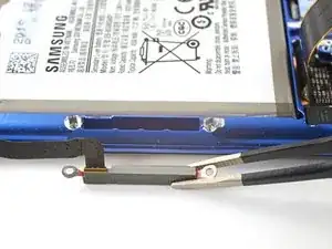
Insert the point of a spudger into the notch on the right side of the upper midframe and pry up to release the clips holding it into place.
-
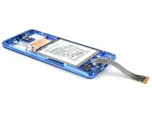
Remove the upper midframe.
-
-
-
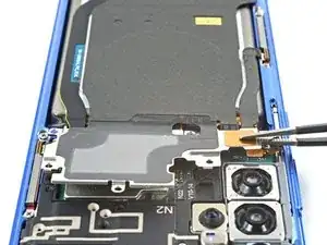
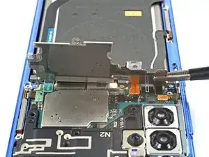
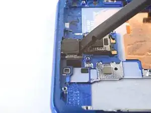
Use a spudger to pry up and disconnect the right 5G mmWave antenna flex cable from the motherboard.
-
Bend the cable out of the way of the motherboard.
-
-
-
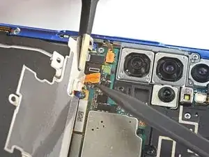
Pry up and disconnect the side button flex cable from the motherboard.
-
Bend the cable out of the way of the motherboard.
-
-
-
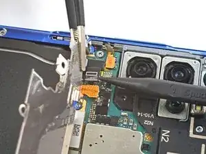
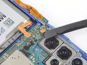
Pry up and disconnect the front facing camera flex cable from the motherboard.
-
Bend the cable out of the way of the motherboard.
-
-
-
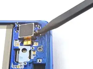
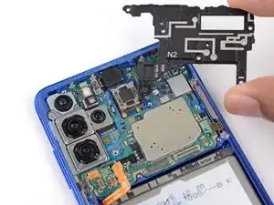
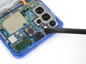
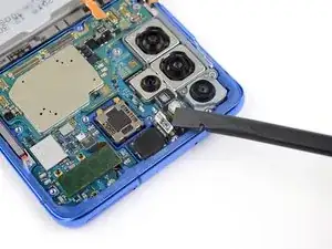
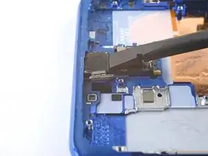
Use the flat end of a spudger to pry up and disconnect the 5G mmWave antenna module.
-
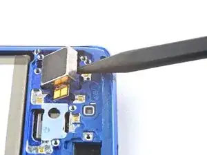
Use the flat end of a spudger to pry up the corner of the antenna module.
-
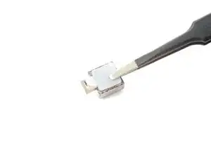
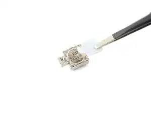
Remove the mmWave antenna module.
-
-
-
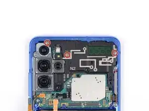
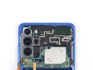
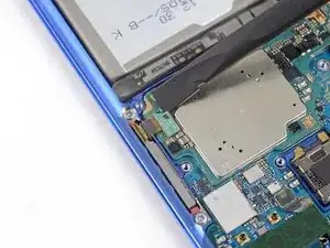
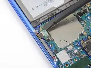
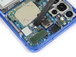
Use a Phillips #00 screwdriver to remove the two screws securing the motherboard and camera assembly:
-
One 4 mm-long screw
-
One 3.4 mm-long screw
-
Screw labelled #3373
-
Screw labelled #3394
-
-
-
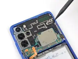
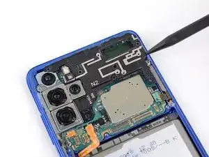
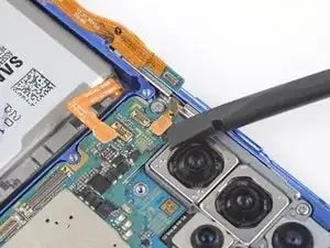
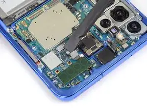
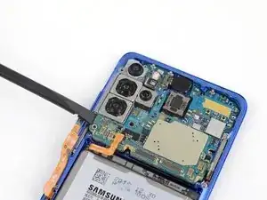
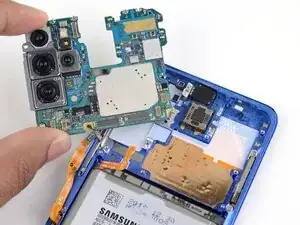
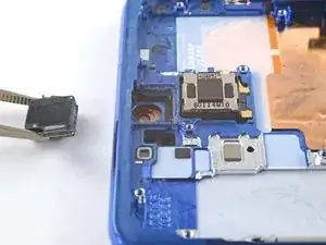
Insert the flat end of a spudger into the bottom left corner of the motherboard assembly and pry up to release it from the phone body.
-
Remove the motherboard assembly.
-
-
-
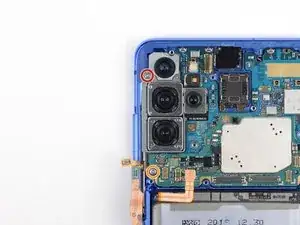
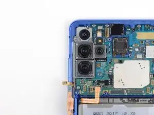
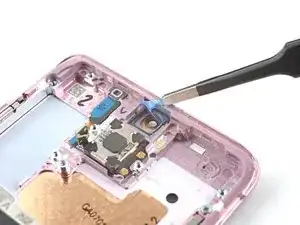
Insert a spudger into the gap between the frame and the front camera.
-
Pry up with the spudger to separate the front camera from the frame.
-
Use tweezers, or your fingers, to remove the front camera.
-
-
-
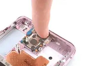
Peel off the front camera adhesive from its liner and apply the sticky end to the frame.
-
Use tweezers, or your fingers, to pull on the tab and expose the top layer of adhesive.
-
Insert the front camera and apply pressure to adhere it to the frame.
-
-
-
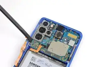
Use a Phillips screwdriver to remove the four 3.4 mm-long screws securing the 5G mmWave antennas.
-
-
-
Use the point of a spudger to pry up on the 5G antenna bracket's bottom screw tab.
-
Use tweezers, or your fingers, to remove the 5G antenna.
-
-
-
Use the point of a spudger to pry up on the 5G antenna bracket's top edge.
-
Use tweezers, or your fingers, to remove the 5G antenna.
-


Compare your new replacement part to the original part—you may need to transfer remaining components or remove adhesive backings from the new part before installing.
To reassemble your device, follow the instructions in reverse order and perform the opposite actions, e.g., "reattach" instead of "removing." Skip steps that use heating and prying, and pay close attention to the 📌 bullets as you work through the steps.
After you've completed the repair, download the Samsung Members App from the Galaxy Store or the Play Store, and Samsung Self-Repair document (beginning page 10) to make sure your device is fully functional.
Download the Self Repair Assistant on your device and follow the Samsung Self-Repair document (beginning page 11) to perform a battery cycle reset.
Take your e-waste to an R2 or e-Stewards certified recycler.
Repair didn’t go as planned? Check out our Answers community for troubleshooting help.

4 comments
I just finished this repair. Note that when separating the back cover, you can go straight in for the top and bottom. The sides have curves in the glass. This requires angling your tool slightly up towards back cover to separate. Too much could scratch the back glass.
Also, between step 23 and #0024 there is a missing step. Before you heat and remove the vibrate component, you need to remove the circuit board for the charging port. There are 3 screws to remove using the #00 Phillips screwdriver. Also, disconnect the two ribbons. You can just disconnect the Main side to remove them with the circuit board.
Finally, I have yet to be able to find the Galaxy Cal APK
Hi Dave.
Thank you for the comment! I have added the missing steps. To find the Galaxy Cal APK, there's a link in the conclusion section labeled "Galaxy Cal App" that should give you the APK.
I really appreciate the response and the link. I downloaded and when I tried to run, after install, the app received the message "Try again after getting new version." The apk was Version 1.0.1-usa. Can you please advise? Thanks.
This requires an immense amount of patience and the persistent use of heat to disassemble this phone. I ended up breaking the front camera module while trying to pry it loose. Fortunately, this is available as a repair part and I was able to replace the front screen, camera, and battery and the phone now works perfectly.