Introduction
Follow this guide to replace the screen and battery assembly on your Samsung Galaxy S21 with a genuine Samsung part.
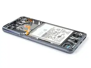
This guide is written for the genuine Samsung screen and battery assembly. The assembly consists of the screen, battery, and frame together in one part. Be sure you have the right part before you begin the repair.
Before you begin, refer to the Samsung Self-Repair document for safety information.
If your battery is swollen, take appropriate precautions. Before disassembling your device, completely discharge the battery. This reduces the risk of a dangerous thermal event if the battery is accidentally damaged during the repair.
Note: Retaining water resistance after the repair will depend on how well you reapply the adhesive, but your device will lose its IP (Ingress Protection) rating.
Some images in this guide may show minor discontinuities. They should not affect the overall guide procedure.
-
-
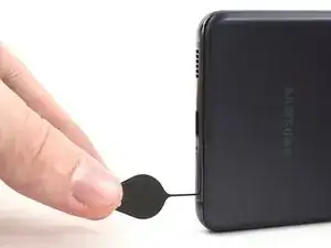
Insert a SIM eject tool, bit, or straightened paper clip into the SIM card tray hole on the bottom edge of the phone.
-
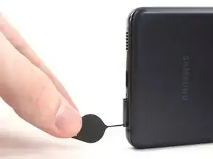
Press the SIM eject tool into the SIM card tray hole to eject the SIM card tray.
-
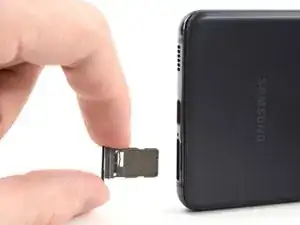
Remove the SIM card tray.
-
-
-
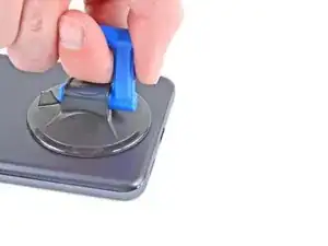
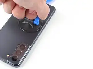
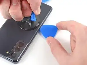
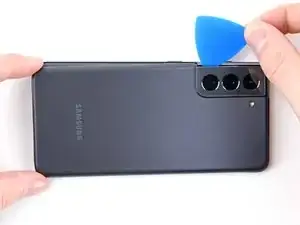
Apply a suction cup to the back of the phone, as close to the center of the bottom edge as possible.
-
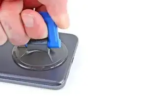
Pull up on the suction cup with strong, steady force to create a gap between the back cover and the frame.
-
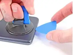
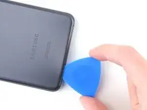
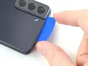
Insert an opening pick into the gap.
-
-
-
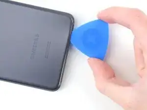
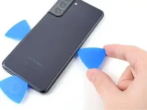
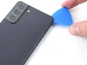
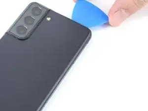
Slide the pick back and forth along the bottom edge to slice through the adhesive.
-
Leave the pick in to prevent the adhesive from resealing.
-
-
-
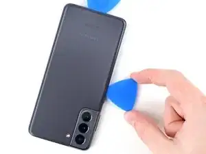
Apply a suction cup to the back of the phone, as close to the center of the left edge as possible.
-
Pull up on the suction cup with strong, steady force to create a gap between the back cover and the frame.
-
Insert an opening pick into the gap.
-
-
-
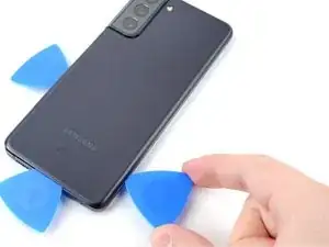
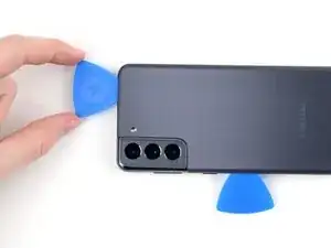
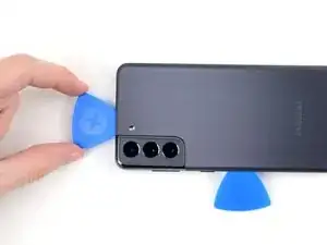
Slide an opening pick along the left edge towards the bottom left corner to cut the adhesive.
-
Leave the pick in to prevent the adhesive from resealing.
-
-
-
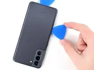
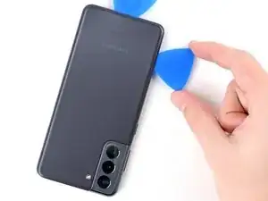
Apply a suction cup to the back of the phone, as close to the center of the right edge as possible.
-
Pull up on the suction cup with strong, steady force to create a gap between the back cover and the frame.
-
Insert an opening pick into the gap.
-
-
-
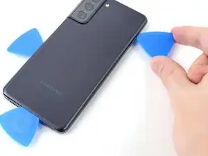
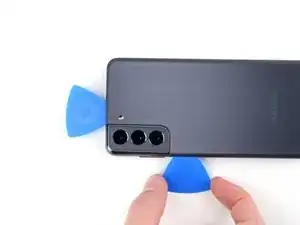
Slide an opening pick back and forth along the back cover's right edge to cut the adhesive.
-
Leave the pick in to prevent the adhesive from resealing.
-
-
-
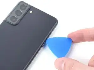
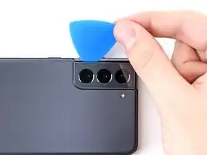
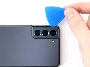
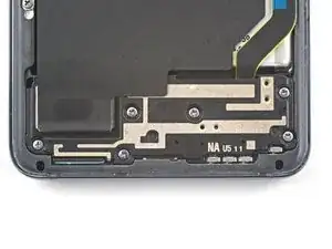
Slide the top-most opening pick as close to the camera shell as possible.
-
Repeat for the left-edge pick.
-
-
-
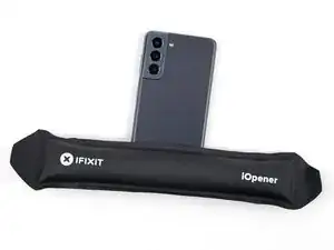
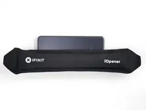
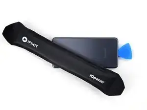
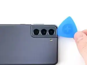
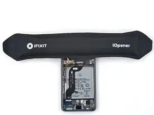
Heat an iOpener and apply it to the camera shell for two minutes.
-
There's additional adhesive to the right of the camera that you need to cut through.
-
Angle the pick downward to avoid any damage.
-
-
-
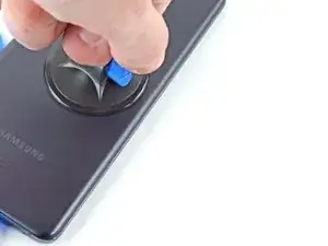
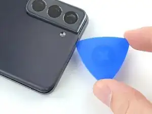
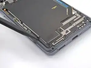
Rotate the back cover counterclockwise to create a gap between the camera shell and the frame.
-
Insert an opening pick in the gap.
-
-
-
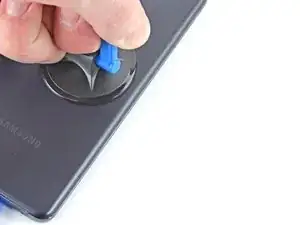
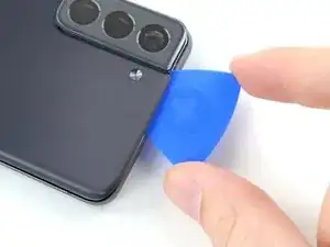
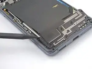
Line up the opening pick's tip with your phone's flash
-
Insert the pick slowly, making sure to avoid the flash's plate.
-
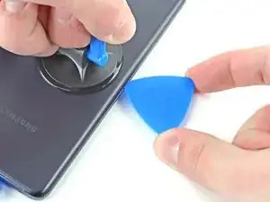
Slice the adhesive to the right of the camera.
-
-
-
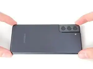
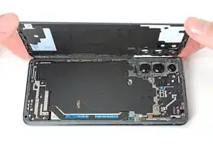
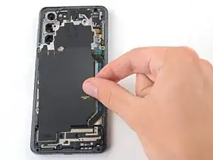
Remove the back cover.
-
This is a good point to power on your phone and test all functions before sealing it up. Be sure to power your phone back down completely before you continue working.
-
Remove any adhesive chunks with a pair of tweezers or your fingers. Apply heat if you're having trouble separating the adhesive.
-
If you're using Samsung custom-cut adhesives, follow this guide.
-
If you're using double-sided tape, follow this guide.
-
-
-
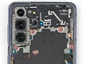
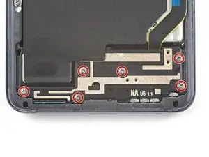
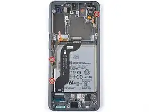
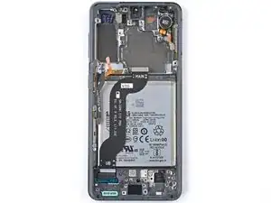
Use a Phillips screwdriver to remove the five 4 mm-long screws securing the motherboard bracket to the frame.
-
-
-
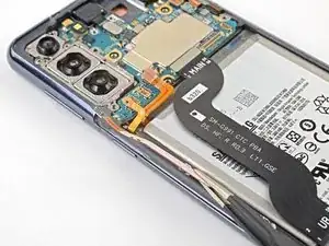
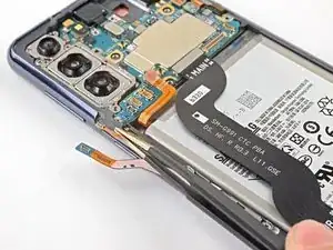
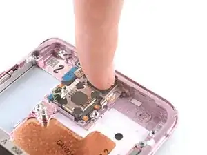
While using tweezers, or your fingers, to hold the motherboard bracket out of the way, use a spudger to pry up the battery press connector.
-
-
-
While holding the motherboard bracket out of the way, use a spudger to pry up and disconnect the wireless charging coil's press connector.
-
-
-
Use a Phillips screwdriver to remove the six 4 mm-long screws securing the loudspeaker to the frame.
-
-
-
Insert the point of a spudger into the notch in the top-left corner of the loudspeaker and pry up to release the clips holding it in place.
-
-
-
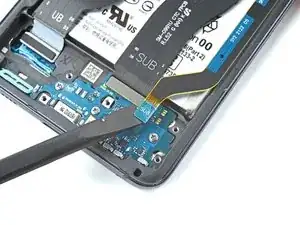
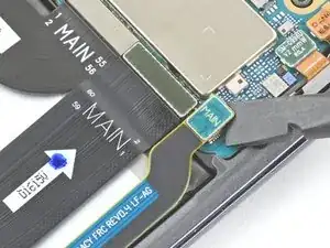
Use the flat end of a spudger to pry up and disconnect the primary interconnect cable's press connector.
-
-
-
Use the flat end of a spudger to pry up and disconnect the secondary interconnect cable's press connector.
-
-
-
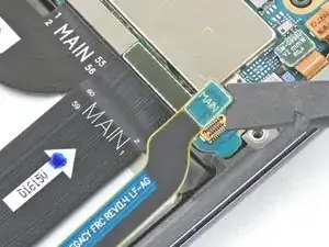
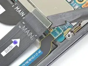
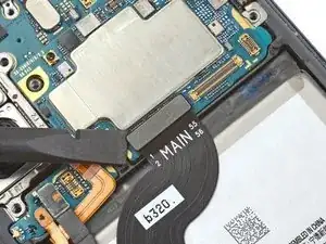
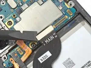
Use a spudger to pry up and disconnect the secondary interconnect cable's press connector.
-
Repeat for the main interconnect cable's press connector.
-
-
-
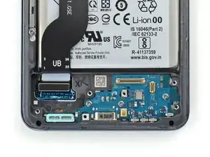
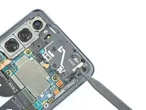
Use a Phillips screwdriver to remove the three 3.5 mm-long screws securing the daughterboard to the frame.
-
-
-
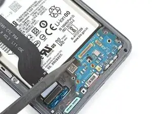
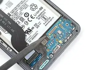
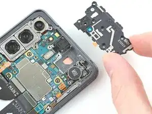
Use the point of a spudger to pry up the daughterboard.
-
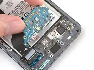
Use your fingers to pull the daughterboard up and away from the bottom of the phone and remove it.
-
-
-
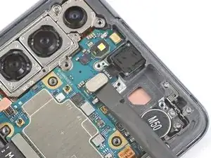
Use the point of a spudger to pry up and disconnect the earpiece speaker cable's press connector.
-
-
-
Use a Phillips screwdriver to remove the seven 4 mm-long screws securing the earpiece speaker to the motherboard.
-
-
-
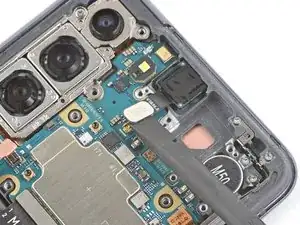
Insert the point of a spudger into the gap between the right-most edge of the earpiece speaker and the phone.
-
Use the spudger to pry up and release the clips holding the earpiece speaker in place.
-
Use tweezers, or your fingers, to remove the earpiece speaker.
-
-
-
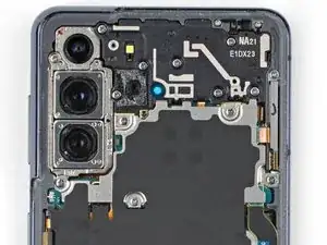
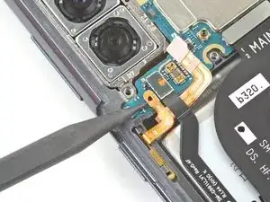
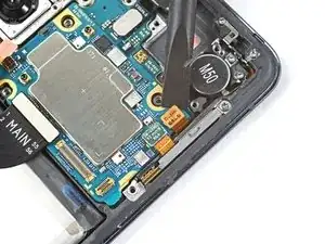
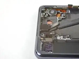
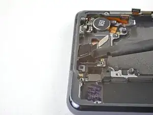
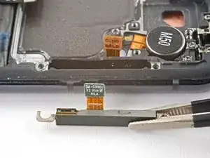
Use a spudger to pry up and disconnect the left 5G mmWave antenna cable's press connector.
-
Repeat for the power button cable's press connector.
-
-
-
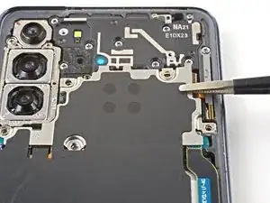
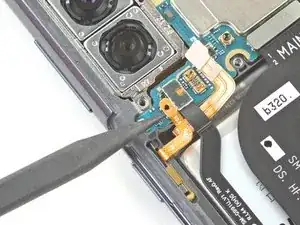
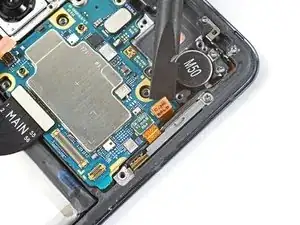
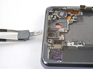
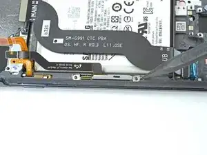
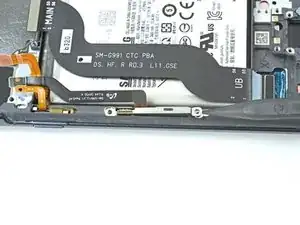
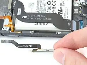
Use tweezers, or your fingers, to bend the power button cable away from the phone.
-
Repeat for the left-edge 5G mmWave antenna cable.
-
-
-
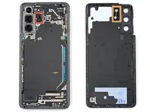
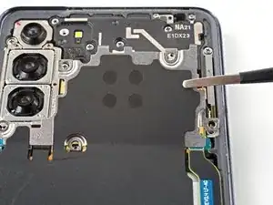
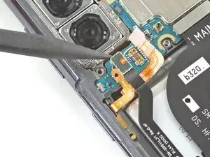
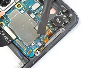
Use a spudger to pry up and disconnect the orange press connector adjacent to the 5G mmWave antenna cable's press connector.
-
Repeat for the green 5G mmWave antenna cable's press connector.
-
-
-
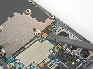
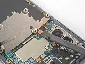
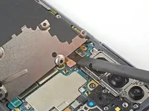
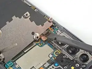
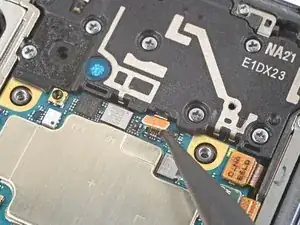
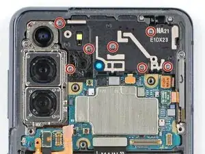
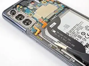
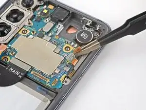
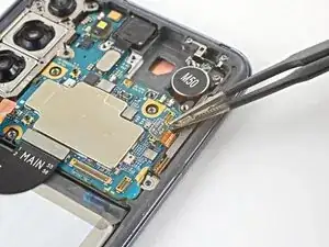
Use a Phillips screwdriver to remove the 4 mm-long screw securing the camera bracket and the motherboard to the frame.
-
-
-
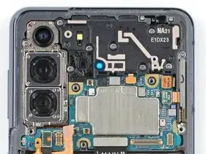
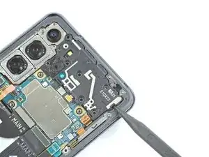
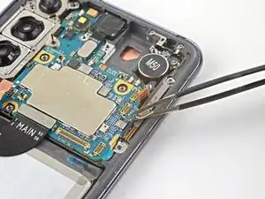
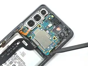
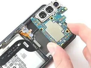
Insert a spudger between the bottom-right edge of the motherboard and the frame.
-
Pry up with the spudger to release the clips securing the motherboard.
-
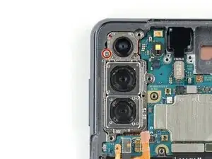
Use your fingers to remove the motherboard.
-
-
-
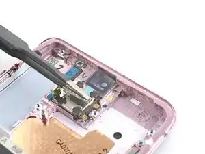
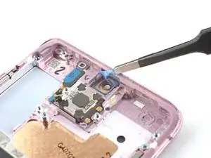
Insert the point of a spudger into the gap between the frame and the front camera.
-
Pry up with the spudger to detach the front camera.
-
Use tweezers, or your fingers, to remove the front camera.
-
-
-
Peel off the front camera adhesive from its liner and apply the sticky end to the frame.
-
Use tweezers, or your fingers, to pull on the tab and expose the top layer of adhesive.
-
Insert the front camera and apply pressure to adhere it to the frame.
-
-
-
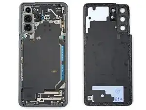
Use a Phillips screwdriver to remove the three 3.5 mm-long screws securing the 5G mmWave antenna brackets to the frame.
-
-
-
Use the point of a spudger to pry up on the right 5G mmWave antenna bracket's bottom screw tab.
-
Use tweezers, or your fingers, to remove the 5G mmWave antenna.
-
-
-
Use the point of a spudger to pry up on the left 5G mmWave antenna bracket's top edge.
-
Use tweezers, or your fingers, to remove the 5G mmWave antenna.
-
-
-
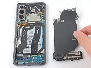
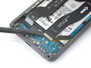
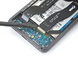
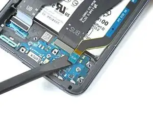
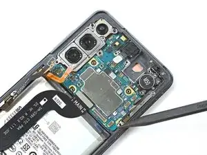
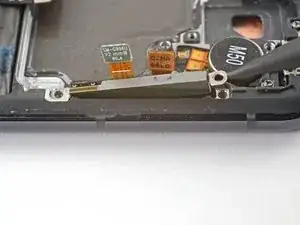
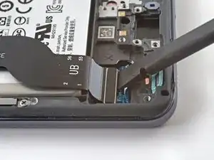
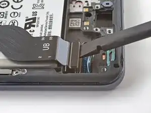
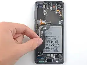
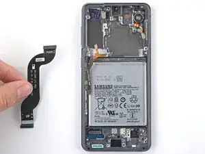
Use a spudger to pry up and disconnect the display cable's press connector near the bottom of the device.
-


To reassemble your device, follow the instructions in reverse order and perform the opposite actions, e.g., "reattach" instead of "removing." Skip steps that use heating and prying, and pay close attention to the 📌 bullets as you work through the steps.
After you've completed the repair, download the Samsung Members App from the Galaxy Store or the Play Store, and follow the Samsung Self-Repair document (beginning page 10) to make sure your device is fully functional.
Download the Self Repair Assistant on your device and follow the Samsung Self-Repair document (beginning page 11) to perform a battery cycle reset.
Take your e-waste to an R2 or e-Stewards certified recycler.
Repair didn’t go as planned? Check out our Answers community for troubleshooting help.

3 comments
This was good overall. Thank you. If you can come up with a suggestion for gluing the front camera back in place properly, that would be great. The tiny Samsung/IFIXIT ring of tape seems ridiculous honestly.
As a note, you need to remove the flex antenna in the top right corner from the old frame and move it over to the new frame, or you won't have signal. This applies even if you have a antenna in the new frame. Takes a tri-point screwdriver bit.
Hi Vincent.
Thank you for your comment! The OEM replacement screen and battery assembly should come with the flex antenna pre-installed, and it should work properly after your repair. If your part didn't come with the antenna, please contact our customer support.