Introduction

Follow this guide to replace the screen and battery assembly in your Samsung Galaxy S22 with a genuine Samsung part.

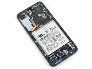
This guide is written for the genuine Samsung screen and battery assembly. The assembly consists of the screen, battery, and frame together in one part. Be sure you have the right part before you begin the repair.

Before you begin, refer to the Samsung Self-Repair document for safety information.

If your battery is swollen, take appropriate precautions. Before disassembling your device, completely discharge the battery. This reduces the risk of a dangerous thermal event if the battery is accidentally damaged during the repair.

Note: Retaining water resistance after the repair will depend on how well you reapply the adhesive, but your device will lose its IP (Ingress Protection) rating.

  1. jIBLZU3XEIKpYmwc
    jIBLZU3XEIKpYmwc
    QO3dkpBpLQBdprAK
    ttrIyvp2tGb1Fhpf
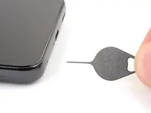
    • Insert a SIM eject tool, bit, or straightened paper clip into the SIM card tray hole on the bottom edge of the phone.

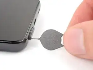
    • Press the SIM eject tool into the SIM card tray hole to eject the SIM card tray.

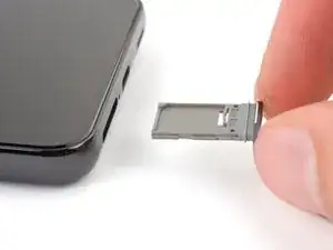
    • Remove the SIM card tray.

    • If you accidentally inserted the SIM eject tool into a microphone hole, don't worry! You most likely didn't damage the microphone.

  2. vNyZTvpxmtsuoSpd
    • Heat an iOpener and apply it to the bottom edge of the back cover for two minutes.

    • A hair dryer, heat gun, or hot plate may also be used, but be careful not to overheat the phone—the display and internal battery are susceptible to heat damage.

  3. YON54aNhBiS4PrTH
    YON54aNhBiS4PrTH
    seCjL4ClIyjmKX6D
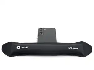
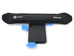
    • While you wait for the adhesive to soften, note the following:

    • There's adhesive securing the back cover around the perimeter of the frame.

    • The adhesive is strongest in the bottom right and top left corners.

  4. YxFOVARobQPP1QR4
    YxFOVARobQPP1QR4
    2srRAIFDtwIFXaO3
    tVPUbDOpBhoqH4V5
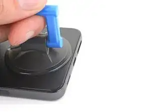
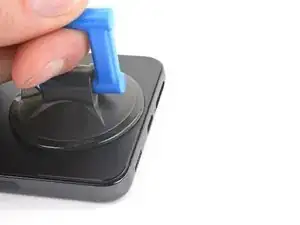
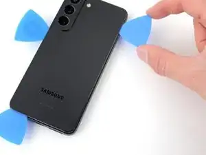
    • Apply a suction cup to the back cover, as close to the bottom edge as possible.

    • Pull up on the suction cup with strong, steady force to create a gap between the cover and the frame.

    • If you have trouble creating a gap, apply more heat to further soften the adhesive. Follow the iOpener instructions to avoid overheating.

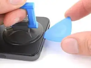
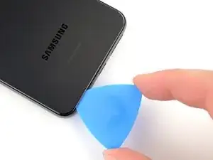
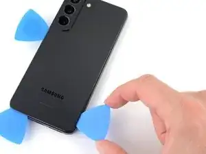
    • Insert an opening pick into the gap.

  5. WLnbDwXlhG4MOJl2
    WLnbDwXlhG4MOJl2
    uHMLOEhtaImqfiIE
    uQ5RQDuVxTILKBGW
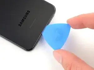
    • Slide the pick back and forth along the bottom edge to slice through the adhesive.

    • Leave the pick inserted in the bottom left corner to prevent the adhesive from resealing.

  6. gKXKJKeQYjBbsHfU
    • Apply a heated iOpener to the left edge of the back cover for two minutes.

  7. 62VpFTVYJRAIXEJt
    62VpFTVYJRAIXEJt
    kBKqJWGYyCGEQfPy
    IyiMLqKuUYELf1nb
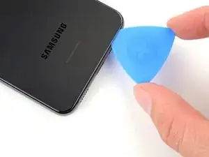
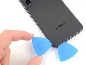
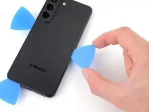
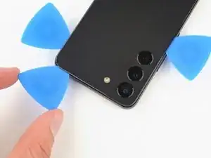
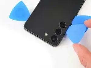
    • Insert a second opening pick at the bottom left corner.

    • Slide the pick to the bottom of the camera bezel to slice the left adhesive.

    • Only insert the pick up to 5 mm, as you may damage the antenna flex cable or the power button cable.

    • Leave the pick in to prevent the adhesive from resealing.

  8. FhTaFqcQ1vxSsa6L
    • Heat an iOpener and apply it to the right edge of the back cover for two minutes.

  9. ZDWRbYhC1c1jpAhH
    ZDWRbYhC1c1jpAhH
    5DbSUfYTkyoVd1qv
    xMcAMI4LpNRWJEDs
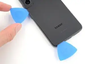
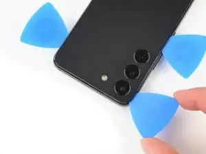
    • Insert a third opening pick at the bottom right corner.

    • If the adhesive has resealed, insert the pick closer to the bottom edge.

    • Slide the pick to the top right corner to slice the adhesive.

    • Leave the pick in the top right corner to prevent the adhesive from resealing.

  10. DFokNwiJlo2s4SVS
    • Heat an iOpener and apply it to the top edge of the back cover for two minutes.

  11. AUBZZFcbTkMlUJhi
    AUBZZFcbTkMlUJhi
    NyjDcgePKJWlgDPP
    AfoogBYpba2mrHZ2
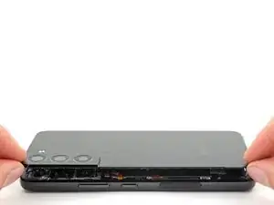
    • Insert an opening pick in the gap at the top right edge.

    • Slide the pick across the top edge and around the top left corner to slice the remaining adhesive.

    • Only insert the pick up to 4 mm, as you may damage the rear cameras or flash.

  12. kLwKvCruLUwnP6ub
    kLwKvCruLUwnP6ub
    2qckA2vYZ2lSYya1
    O6I4YVbwWwyFvN1q
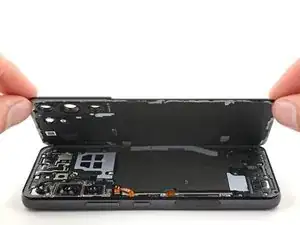
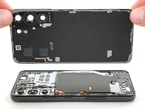
    • Grab and remove the back cover.

    • If your cover is still sticking to the frame, slide an opening pick around the perimeter until the cover completely separates.

    • During reassembly:

    • This is a good point to power on your phone and test all functions before sealing it up. Be sure to power your phone back down completely before you continue working.

    • Remove any adhesive chunks with a pair of tweezers or your fingers. Apply heat if you're having trouble separating the adhesive.

    • To apply new adhesive, follow this guide.

  13. aKCJXduIcwPEN2rh
    aKCJXduIcwPEN2rh
    HpFDyFeSynreDYVt
    • Use the pointed end of a spudger to pry and disconnect the wireless charging coil from the motherboard.

    • To re-attach press connectors, carefully align and press down on one side until it clicks into place, then repeat on the other side. Don't press down on the middle. If the connector is misaligned, the pins can bend and cause permanent damage.

  14. QU6VDaABwB4KFtDG
    • If you're using the Samsung Self Repair Kit, take a moment to identify your screws and label them accordingly:

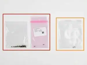
    • Label the bag with the most screws and the colored bag #3428.

    • If you're replacing the screen and battery, label the clear bag with two screws #3229.

  15. AE4QbvOGd1mGn4eS
    AE4QbvOGd1mGn4eS
    juSC3X6EpWkVwGsP
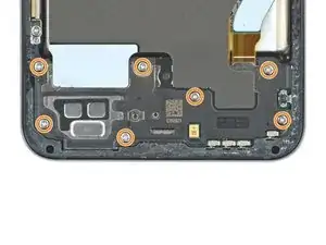
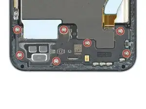
    • Use your Phillips screwdriver to remove the six 3.5 mm-long screws securing the wireless charging coil.

    • If you're reassembling with the Samsung Self-Repair kit, be sure to replace the screws with the new ones labeled #3428.

  16. bptEIHWSoIvHnV6T
    • Use your Phillips screwdriver to remove the seven 3.5 mm screws securing the loudspeaker.

    • If you're reassembling with the Samsung Self-Repair kit, be sure to replace the screws with the new ones labeled #3428.

  17. KgkxN4rnWYOOYCCj
    KgkxN4rnWYOOYCCj
    kRCZtqZR2txYyVMX
    Ds1WRYnZOKhxMiDw
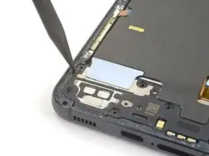
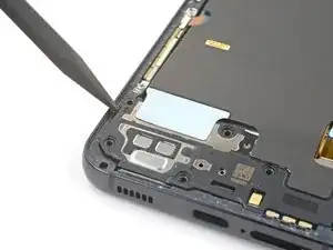
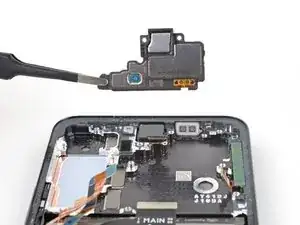
    • Insert the pointed end of your spudger between the upper left corner of the loudspeaker and the frame.

    • Pry up to unclip the loudspeaker from the frame.

    • During reassembly, press around the perimeter of the loudspeaker to engage the clips.

  18. FrNwOCsmhWXXSeMe
    FrNwOCsmhWXXSeMe
    A3JyQGRrPFeXkWAo
    RDWAUlIpGiCdlPMc
    • Grab and remove the wireless charging coil and loudspeaker from the frame.

    • Do not separate the charging coil from the loudspeaker.

  19. BmMXmHSqjwHBE3co
    BmMXmHSqjwHBE3co
    oZsI1A3jWoECYYvB
    • Use the pointed end of your spudger to pry up and disconnect the battery press connector.

  20. DnLI6tsgLB6AZBnA
    DnLI6tsgLB6AZBnA
    LpJUeoLITW4s2Dal
    5gZEnYUSQ3bEQayB
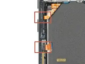
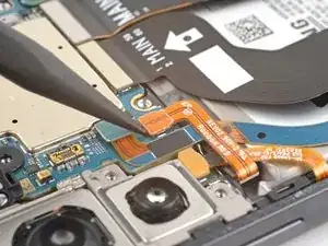
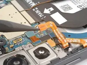
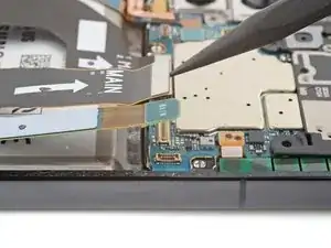
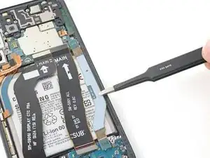
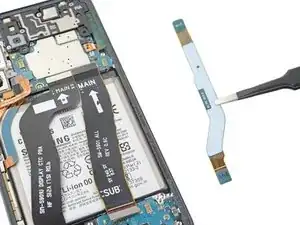
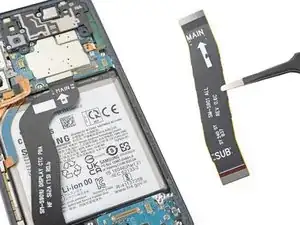
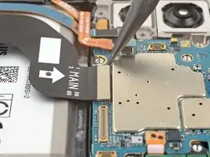
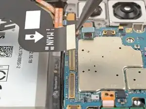
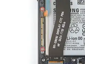
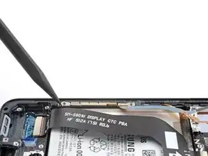
    • Use the pointed end of your spudger to pry up and disconnect both interconnect cables from the motherboard.

  21. I5voYwmLb5NGpdKV
    I5voYwmLb5NGpdKV
    RrsijEGy1guqimNF
    HTv3TL1VJGoVeBGw
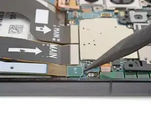
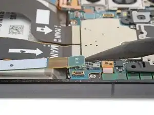
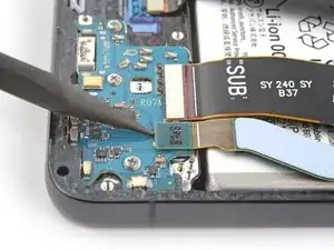
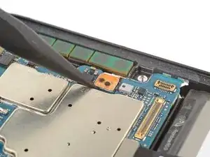
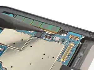
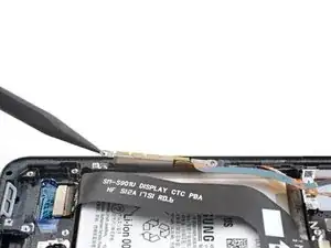
    • Use the pointed end of your spudger to pry up and disconnect both interconnect cables from the charging board.

  22. EdgKJGCEC3Zqeccd
    EdgKJGCEC3Zqeccd
    uoS1dojO3WOvZOlr
    vr4MCULBK3wlkq2D
    • Grab and remove the two interconnect cables from the frame.

    • During reassembly, orient the cables so the "main" ends are toward the top of the phone and the "sub" ends are toward the bottom.

  23. vJI2HfshlwRhEtx1
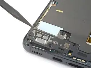
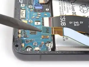
    • Use your Phillips screwdriver to remove the four 3.5 mm-long screws securing the motherboard cover.

    • If you're reassembling with the Samsung Self-Repair kit, be sure to replace the screws with the new ones labeled #3428.

  24. BqANkwMIwwj3bTrN
    BqANkwMIwwj3bTrN
    HFOmLKLjCDLRGL2g
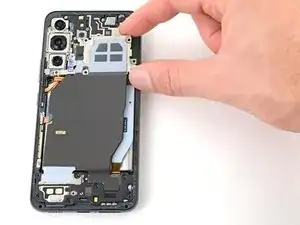
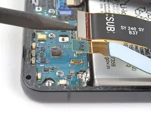
    • Insert the pointed end of your spudger between the bottom of the motherboard cover and the motherboard.

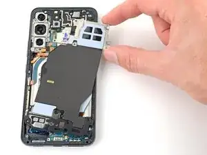
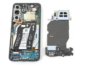
    • Pry up on the cover to unclip it from the frame.

  25. UAKtt3AnvBYservK
    UAKtt3AnvBYservK
    yxNa2rDZfpKYGZBP
    • Grab and remove the motherboard cover.

  26. BW4pXHPR6IF2FoJQ
    BW4pXHPR6IF2FoJQ
    3gXxsw6DmeBhnOkX
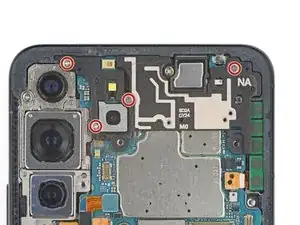
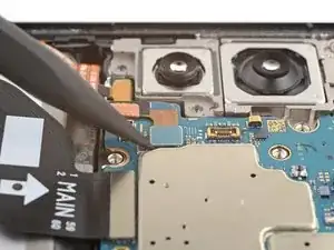
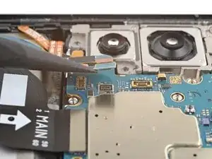
    • Use the pointed end of your spudger to pry up and disconnect the left 5G mmWave antenna press connector.

  27. RxacHjvkjNObYnNT
    RxacHjvkjNObYnNT
    5BTfXguMMNQskplb
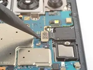
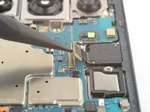
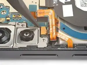
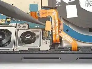
    • Use the pointed end of your spudger to pry up and disconnect the front-facing camera press connector.

  28. xcRO2KDCohJEHM3Q
    xcRO2KDCohJEHM3Q
    3UZoPRsV2UAYeatS
    • Use the pointed end of your spudger to pry up and disconnect the screen press connector.

  29. WCUxxVZyDHqd4pwx
    WCUxxVZyDHqd4pwx
    djOQ2aGHCRP3hXSI
    • Use the pointed end of your spudger to pry up and disconnect the right 5G mmWave antenna press connector.

  30. N5n15FnZGQmGoFtL
    N5n15FnZGQmGoFtL
    SG1UcHQNXLhJVHu4
    • Use the pointed end of your spudger to pry up and disconnect the power and volume button's press connector.

    • During reassembly, make sure this cable is under the battery cable.

  31. vZssCYAgpQGhMYx1
    • Use your Phillips screwdriver to remove the 3.5 mm-long screw securing the motherboard.

    • If you're reassembling with the Samsung Self-Repair kit, be sure to replace the screw with the new one labeled #3428.

  32. rTHTqs2DCT34OJrC
    rTHTqs2DCT34OJrC
    3bW3T4kgJQNERIiT
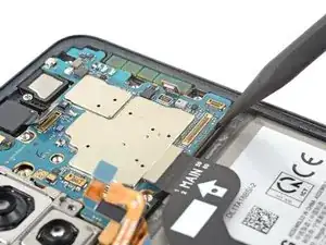
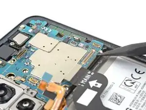
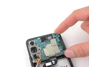
    • Insert the pointed end of your spudger between the bottom right of the motherboard and the frame.

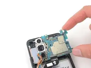
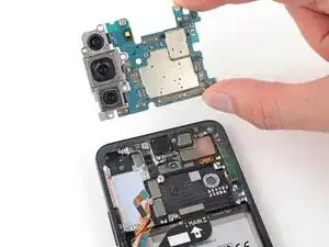
    • Pry the motherboard up until you can grab it with your fingers.

  33. QKgEZvivNu1fPlc2
    QKgEZvivNu1fPlc2
    pYxhOCxowPQHh2wT
    YVdaxAD5YtVWdKK1
    • Grab the motherboard by the right edge and remove it from the frame.

    • Be careful not to catch the motherboard on any loose cables.

    • During reassembly, be sure the cables are above the motherboard when reinserting it.

  34. 4TFDs1XH2FXZkESu
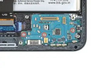
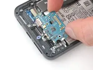
    • Use your Phillips screwdriver to remove the three 3.5 mm-long screws securing the charging board.

    • If you're reassembling with the Samsung Self-Repair kit, be sure to replace the screws with the new ones labeled #3428.

  35. P6wFQCFo4TmDpOiO
    P6wFQCFo4TmDpOiO
    bLNHuMnxooYYKNsy
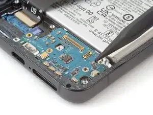
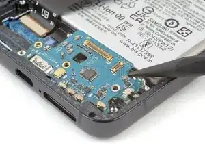
    • Insert the pointed end of your spudger between the top right of the charging board and the frame.

    • Pry the charging board up from its recess until you can grab it with your fingers.

  36. d3j2D1dyILA5kG5i
    d3j2D1dyILA5kG5i
    JvXF4shNWRJ4DS5M
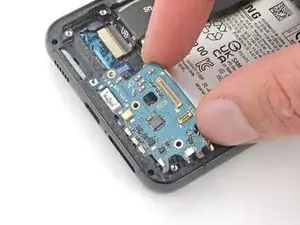
    • Grip the charging board by its corners and slide it out of its recess in the frame.

    • Remove the charging board.

    • During reassembly, reinsert the charging board at a downward angle to guide the USB-C port into its recess.

  37. WfCSQgRSCyggJ5md
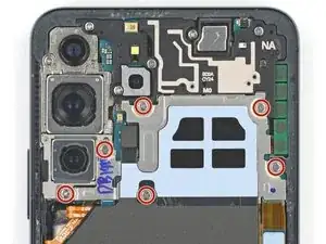
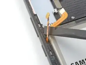
    • Use your Phillips screwdriver to remove the two 2.9 mm-long screws securing the earpiece speaker and vibration motor.

    • If you're reassembling with the Samsung Self-Repair kit, be sure to replace the screws with the new ones labeled #3229.

  38. APxDOdXChP6GZlQ1
    APxDOdXChP6GZlQ1
    JIsLPhIRvQ6lkxWB
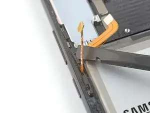
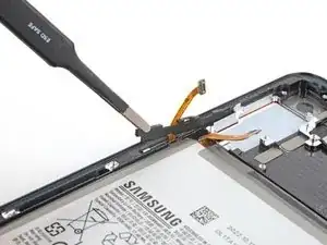
    • Insert the pointed end of your spudger under the left edge of the earpiece speaker and vibration motor.

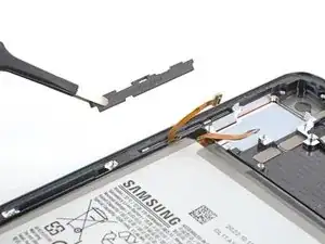
    • Pry up to unclip the earpiece speaker and vibration motor from the frame.

  39. Wxde3Sr6dbXw5MUd
    Wxde3Sr6dbXw5MUd
    TUhy4jlgh2fRxKPa
    • Grab and remove the earpiece speaker and vibration motor.

  40. K6QDHkW3XVMXLOnT
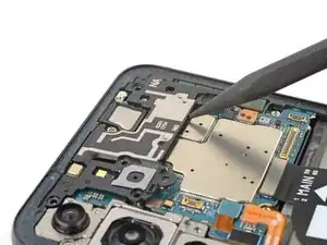
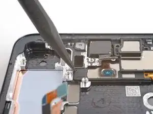
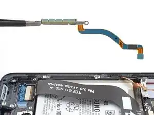
    • Use your Phillips screwdriver to remove the two 3.5 mm-long screws securing the lower 5G mmWave antenna.

    • If you're reassembling with the Samsung Self-Repair kit, be sure to replace the screws with the new ones labeled #3428.

  41. VK54NjQ3coZSjuDf
    VK54NjQ3coZSjuDf
    soJ2DCD4CBMlc2m5
    uBD5NqlSIe1IcmZi
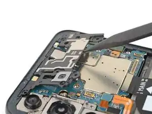
    • Insert the pointed end of your spudger between the lower screw mount of the antenna bracket and the frame.

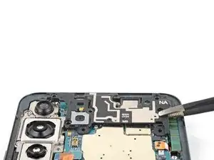
    • Pry up on the bracket until you can grab it with blunt nose tweezers or your fingers.

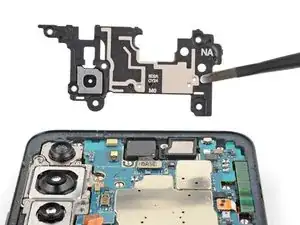
    • Remove the lower 5G mmWave antenna.

  42. JgUSKkPHl36MdUG2
    JgUSKkPHl36MdUG2
    GEweF6fB13cBlhJ2
    FmCArQKVB41ghf2h
    • Before reinstalling the lower 5G mmWave antenna, replace the bracket with a new one. If you don't have a new bracket, skip this step.

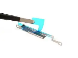
    • Remove the antenna and connector from the old bracket.

    • Remove the L-shaped adhesive liner from your new bracket.

    • Place the antenna in the bracket's recess with the connector fed underneath the longer screw mount.

    • Remove the thin adhesive liner on the outside of the bracket before installing it in the frame.

  43. VwMqg4qUdFQQ5VEe
    VwMqg4qUdFQQ5VEe
    grB3VWCSIuTBPU2R
    QNvexjsylcnvqFYx
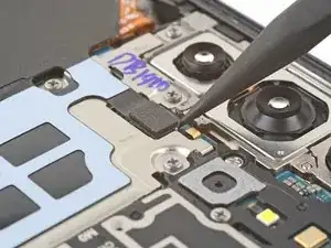
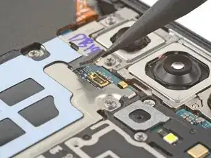
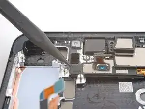
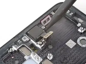
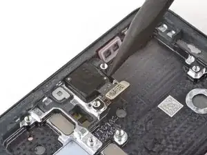
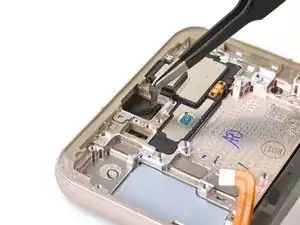
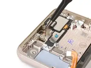
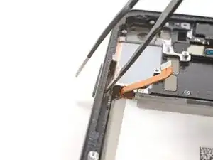
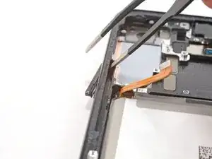
    • Insert the pointed end of your spudger in the gap between the upper 5G mmWave antenna and the frame

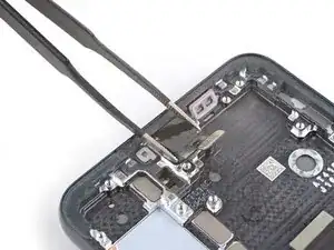
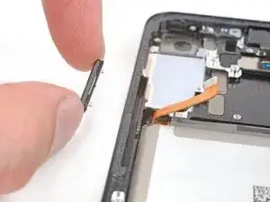
    • Pry the antenna out of its recess until you can grab it with your fingers or blunt nose tweezers.

    • If the antenna feels stuck, apply a heated iOpener for two minutes to soften the adhesive.

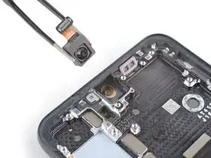
    • Remove the upper 5G mmWave antenna.

  44. pakcQmOXlWTBJKEA
    pakcQmOXlWTBJKEA
    lAPYPS6rHJpQBC1Q
    HWZOsINsCVIOSxF5
    • Replace the adhesive on the upper 5G mmWave antenna before reinstalling it. If you don't have replacement adhesive, reuse your old one or use custom-cut adhesive.

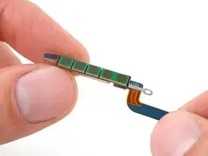
    • Remove the existing adhesive from the antenna with blunt nose tweezers or your fingers.

    • Remove the clear liner from your new adhesive.

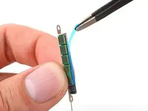
    • Apply the new adhesive to the bottom of the antenna, with its round end farthest from the connector.

    • Remove the green liner from the adhesive before reinstalling the antenna in the frame.

  45. oEBE6XWOUO6yV6aw
    • Heat an iOpener and apply it to the top of the screen for two minutes.

    • A hair dryer, heat gun, or hot plate may also be used, but be careful not to overheat the phone—the display is susceptible to heat damage.

  46. AtZLqFRxBmsRXkLS
    AtZLqFRxBmsRXkLS
    xuGqvAhh1oK2uNpN
    • The adhesive securing the camera is very strong. Work slowly and apply more heat if the camera feels stuck. Avoid separating the circuit board from the camera, like this.

    • Use the pointed end of your spudger to pry the front-facing camera from its recess.

    • If the camera doesn't loosen, use your SIM card eject tool to scrape away the epoxy surrounding the camera.

  47. LbWthYgSp5JQVVGv
    LbWthYgSp5JQVVGv
    slc1FTLNwfmiJEhj
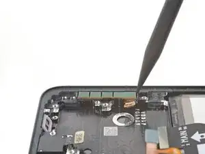
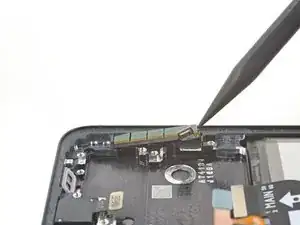
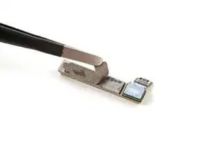
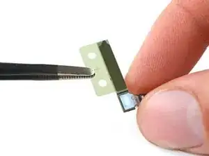
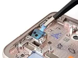
    • Use a pair of blunt nose tweezers to grab and remove the front-facing camera from its recess.

  48. kZg5kZ6TleqjnSkR
    kZg5kZ6TleqjnSkR
    KA4bMno1swI23MXd
    • During reassembly, prepare your new frame for the front-facing camera:

    • Remove the black adhesive liner from the front-facing camera recess.

    • Peel and remove the foam liner from the new frame.

    • This liner isn't necessary for the repair.

  49. 2JqDMEC2w6DRQTDY
    2JqDMEC2w6DRQTDY
    nrcEkA21AUwdufcT
    • Before installing the front-facing camera, replace the adhesive in the frame:

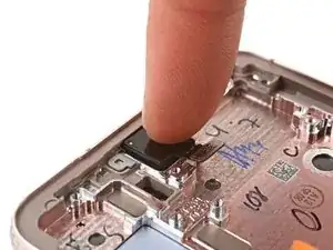
    • Remove the clear liner from the front-facing camera adhesive.

    • Place the adhesive in the camera recess with its pull tab facing right.

    • Remove the blue adhesive liner using its pull tab.

    • Insert the front-facing camera into its recess in the frame and apply pressure to secure it.

  50. E1SVKxP1PGZvGiXl
    E1SVKxP1PGZvGiXl
    TlTmSJBKMOsRMRBh
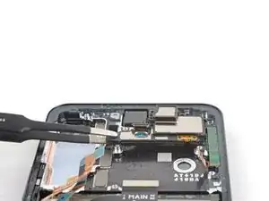
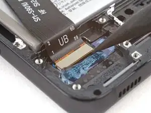
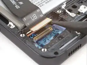
    • Use the pointed end of your spudger to pry up and disconnect the display cable press connector.

  51. CGKQyd2rnCPv2hQa
    CGKQyd2rnCPv2hQa
    UXZJDkOCDAmklYxE
    • Grab and remove the display cable from the frame.

  52. 2xIJt6yvsgk4TBFy
    2xIJt6yvsgk4TBFy
    sOsLMPwdHarcqHZs
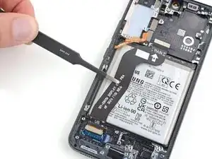
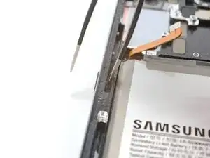
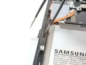
    • Insert the corner of your spudger in the tab on the power and volume button bracket.

    • Twist the spudger upward to pry and loosen the bracket from its recess in the frame.

    • During reassembly, press each button to make sure they "click." They should have the same sound and feel as before disassembly.

  53. m5Sfr3Tqu6gxd2px
    m5Sfr3Tqu6gxd2px
    JTYeu3OYNbyTBFfW
    i1myTDUCkd2daIVT
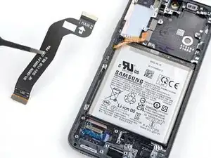
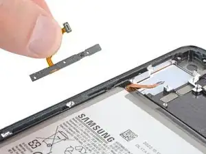
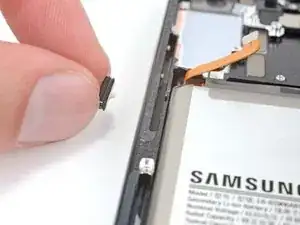
    • Use blunt nose tweezers or your fingers to grab and remove the power and volume button bracket.

    • The button pad may come out with the bracket.

    • Use your fingers to grab and remove the button pad.

    • During reassembly, insert the button pad first. Then, insert the bracket against the back of the button pad. Together, they look like this.

  54. ryveOMAD3kCPiFLa
    ryveOMAD3kCPiFLa
    GSokgJZFDaQMTvvZ
    UL4mcSVRj4PMGf13
    • Insert one arm of your blunt nose tweezers into the power button's recess.

    • Press against the power button's peg to separate it from the frame enough so you can grab the button with your fingers.

    • If blunt nose tweezers don't reach deep enough into the recess, use the bent tip of a paperclip or a similarly-shaped object.

    • Use your fingers to grab and remove the power button.

  55. stKBOiQUxTRE5G4r
    stKBOiQUxTRE5G4r
    CDom3fQvRWxD5H6Y
    WubJ4B4t5TdFnlmw
    • Insert one arm of your blunt nose tweezers into the volume button's recess.

    • Press against both of the volume button's pegs to separate them from the frame enough so you can grab the buttons with your fingers.

    • If blunt nose tweezers don't reach deep enough into the recess, use the bent tip of a paperclip or a similar-shaped object.

    • Use your fingers to grab and remove the volume buttons.

  56. aFIhQQeshHkKImmk
    • You're now left with the screen and battery assembly.

    • Compare your new replacement part to the original part—be sure to transfer remaining components and remove adhesive backings from the new part before installing.

Conclusion

To reassemble your device, follow the instructions in reverse order and perform the opposite actions, e.g., "reattach" instead of "removing." Skip steps that use heating and prying, and pay close attention to the 📌 bullets as you work through the steps.

After you've completed the repair, download the Samsung Members App from the Galaxy Store or the Play Store, and Samsung Self-Repair document (beginning page 9) to make sure your device is fully functional.

Download the Self Repair Assistant on your device and follow the Samsung Self-Repair document (beginning page 11) to perform a battery cycle reset.

Take your e-waste to an R2 or e-Stewards certified recycler.

Repair didn’t go as planned? Check out our Answers community for troubleshooting help.

Clay Eickemeyer

Member since: 19/09/22

22501 Reputation

0 comments