Introduction

This is a prerequisite-only guide! This guide is part of another procedure and isn't meant to be used alone.

  1. gNkOBiPPpophUDNr
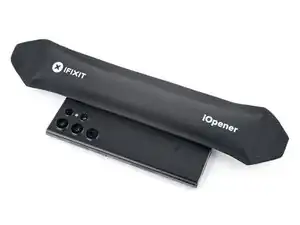
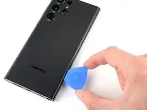
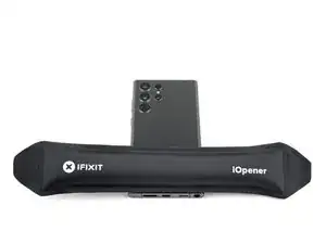
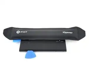
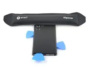
    • Heat an iOpener and apply it to the right edge of the back cover for two minutes.

    • A hair dryer, heat gun, or hot plate may also be used, but be careful not to overheat the phone—the display and internal battery are susceptible to heat damage.

  2. kYc43bqgcFdoWxId
    kYc43bqgcFdoWxId
    byEoPoLBxQl3sP31
    • While you wait for the adhesive to soften, note the following:

    • There's adhesive securing the back cover around the perimeter of the frame.

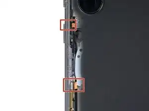
    • The adhesive is strongest in the bottom right and top left corners.

  3. vMQmqEcgrXmLtjLt
    vMQmqEcgrXmLtjLt
    xv4POooYFbuFFQaL
    1ew2vBskdRhjA1oc
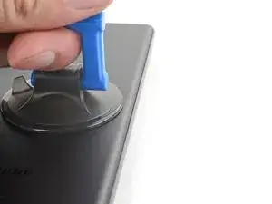
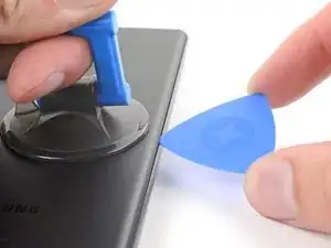
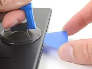
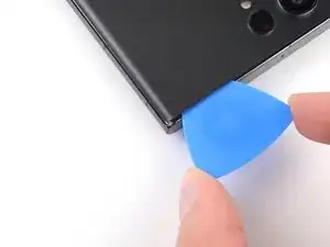
    • Apply a suction cup to the back cover, as close to the center of the right edge as possible.

    • Pull up on the suction cup with strong, steady force to create a gap between the cover and the frame.

    • If you have trouble creating a gap, apply more heat to further soften the adhesive. Follow the iOpener instructions to avoid overheating.

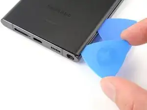
    • Insert an opening pick into the gap.

  4. epeLbFTQBXjV2jZW
    epeLbFTQBXjV2jZW
    m6ugW1SmIVnKgjbL
    JxOIJfnD5MqPsSIZ
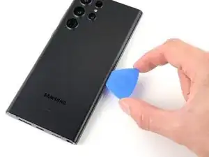
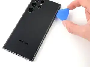
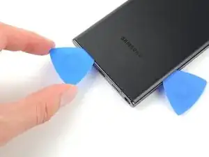
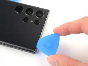
    • Slide the pick back and forth along the right edge to slice through the adhesive.

    • Leave the pick inserted near the bottom of the right edge to prevent the adhesive from resealing.

  5. KFdNe44w3fG4TbWI
    • Apply a heated iOpener to the bottom edge of the back cover for two minutes.

  6. EL5XPENpDlhIiOyA
    EL5XPENpDlhIiOyA
    wRhFidJoSdjeGULV
    WUD33WamJEQHTyHI
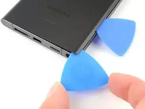
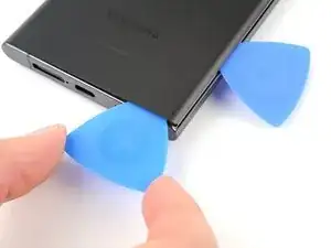
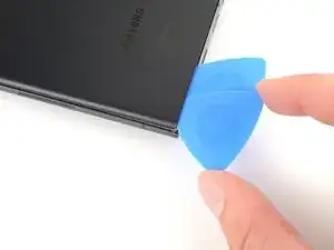
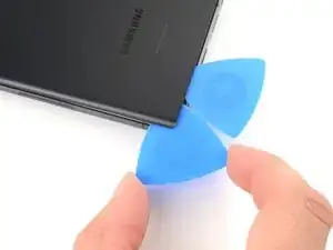
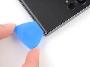
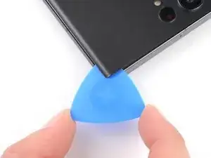
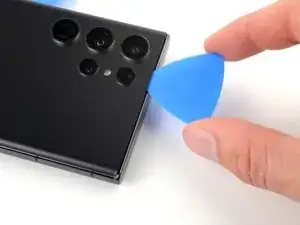
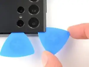
    • Insert a second opening pick at the bottom right corner.

    • Angle the pick upward to match the curved edge and rotate it around the bottom right corner.

    • Be careful while slicing around the corners, as the glass is very fragile here. Work slowly to avoid cracking the glass.

  7. cty2RNPr1Xsulgpr
    cty2RNPr1Xsulgpr
    nXBxWO6bjwLC6cnM
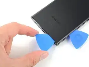
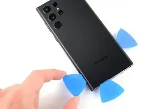
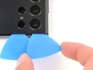
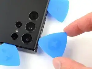
    • Slide your opening pick to the bottom left corner to slice the adhesive.

    • Leave the pick in the bottom left corner to prevent the adhesive from resealing.

  8. IEXDLNdqR3xFYkmP
    • Apply a heated iOpener to the left edge of the back cover for two minutes.

  9. mxXPBGcWiCJfJ3BS
    mxXPBGcWiCJfJ3BS
    olFGEuhIxCIMJcdh
    Arf4HwrTgVSrTFcF
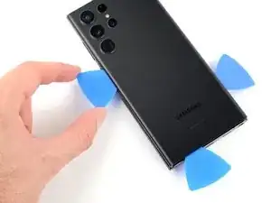
    • Insert a third opening pick at the bottom left corner.

    • Angle the pick upward to match the curved edge and rotate it around the bottom left corner.

    • Be careful while slicing around the corners, as the glass is very fragile here. Work slowly to avoid cracking the glass.

  10. WQmptomBoBQeKuJX
    WQmptomBoBQeKuJX
    4xUwuDfsngL1cFlA
    lkBfZG4mnYPnx1Sb
    • Slide your opening pick along the left edge to slice the adhesive, stopping when you reach the power button.

    • Only insert the pick up to 5 mm, as you may damage the antenna flex cable or the power button cable.

    • Leave the pick in the left edge to prevent the adhesive from resealing.

  11. YMTlXG5toWQfJoLs
    • Heat an iOpener and apply it to the top edge of the back cover for two minutes.

  12. XfPcTdZECHnXRILb
    XfPcTdZECHnXRILb
    MGUhrVwiAaWJfCKS
    tFFB6IAGHuBb5NvR
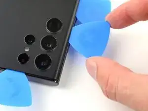
    • Insert an opening pick in the gap at the top right edge.

    • Angle the pick upward to match the curved edge and rotate it around the top right corner.

    • Be careful while slicing around the corners, as the glass is very fragile here. Work slowly to avoid cracking the glass.

  13. AuYJOFYpAYcxqteY
    AuYJOFYpAYcxqteY
    oxPnH3tCjYANEWsu
    • Slide the pick to the top left corner to slice the adhesive.

    • Only insert the pick up to 4 mm, as you may damage the cameras or sensors.

    • Leave the pick in to prevent the adhesive from resealing.

  14. ypnYS5EupERNUwVm
    ypnYS5EupERNUwVm
    GceGlFTsFRUWDKiq
    • Only insert the pick up to 4 mm, as you may damage the cameras.

    • Insert an opening pick in the gap at the top left edge.

    • Angle the pick upward to match the curved edge and rotate it around the top left corner.

  15. NaNGOKtwpRwEUZYI
    NaNGOKtwpRwEUZYI
    RSCerWvIrEVKfxol
    • Only insert the pick up to 4 mm, as you may damage the cameras.

    • Slide the pick toward the bottom camera to slice through the remaining adhesive, stopping before you reach the power button.

  16. 6KZlteiv3dn3pxHZ
    6KZlteiv3dn3pxHZ
    jHQ6dlD1wdCYxMDh
    GQuLOoFxfNlkTyID
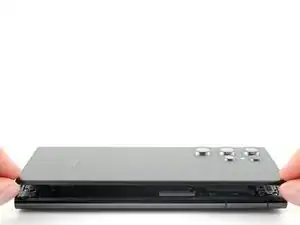
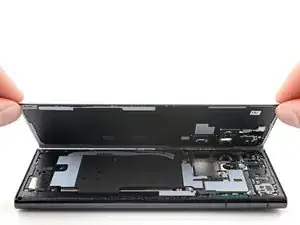
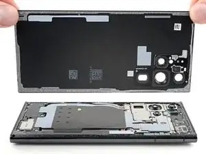
    • Grab and remove the back cover.

    • If your cover is still sticking to the frame, slide an opening pick around the perimeter until the cover completely separates.

    • During reassembly:

    • This is a good point to power on your phone and test all functions before sealing it up. Be sure to power your phone back down completely before you continue working.

    • Remove any adhesive chunks with a pair of tweezers or your fingers. Apply heat if you're having trouble separating the adhesive.

    • If you're using Samsung custom-cut adhesives, follow this guide.

    • If you're using double-sided tape, follow this guide.

  17. NlWmTFLIZEbOfCH4
    NlWmTFLIZEbOfCH4
    AHnQXWp3tJ46AijX
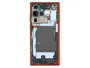
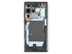
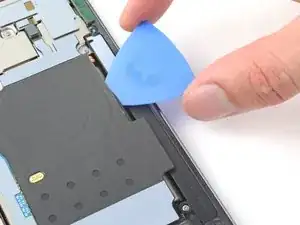
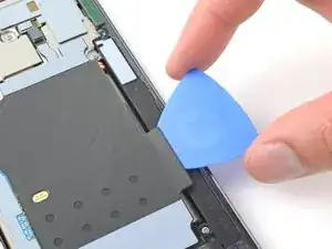
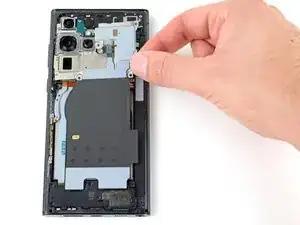
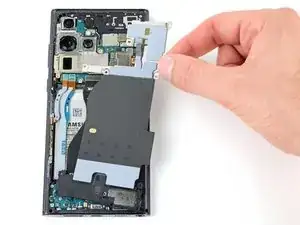
    • The wireless charging coil is lightly adhered to the battery.

    • Insert an opening pick between the right edge of the wireless charging coil and the battery.

    • Slide the pick along the right edge to separate the adhesive.

  18. LkkFQBAUpkc3A6lo
    LkkFQBAUpkc3A6lo
    qHnhXAvFUFxYjrqI
    dYSjnrwnIHpJAxTK
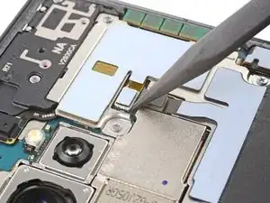
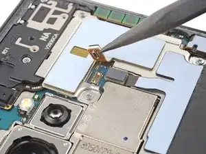
    • Use the pointed end of a spudger to pry and disconnect the NFC antenna press connector from the motherboard.

    • Repeat for the wireless charging coil press connector.

    • To re-attach press connectors, carefully align and press down on one side until it clicks into place, then repeat on the other side. Don't press down on the middle. If the connector is misaligned, the pins can bend and cause permanent damage.

  19. FdOvtNrMGmSEvs1L
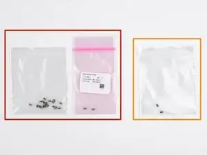
    • If you're using the Samsung Self Repair Kit, take a moment to identify your screws and label them accordingly:

    • Label the bag with the most screws and the colored bag #3428.

    • If you're replacing the screen and battery, label the clear bag with two screws #3439.

  20. PWL4r4HXGRHqY1XV
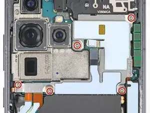
    • Use your Phillips screwdriver to remove the five 3.5 mm-long screws securing the NFC antenna and charging coil.

    • If you're reassembling with the Samsung Self-Repair kit, be sure to replace the screws with the new ones labeled #3428.

  21. GlXu2jnEUd2TqHBG
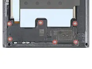
    • Use your Phillips screwdriver to remove the six 3.5 mm screws securing the loudspeaker.

    • If you're reassembling with the Samsung Self-Repair kit, be sure to replace the screws with the new ones labeled #3428.

  22. mrHaOwFjtYwy6FqR
    mrHaOwFjtYwy6FqR
    RxNg3tgcUVbdh5Ro
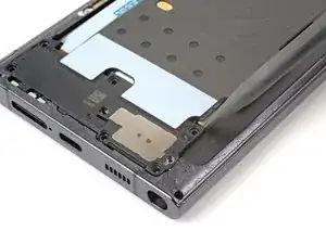
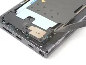
    • Insert the pointed end of your spudger between the upper right corner of the loudspeaker and the frame.

    • Pry up to unclip the loudspeaker from the frame.

    • Don't pry against the battery. Use protrusions in the frame for leverage.

    • During reassembly, press around the perimeter of the loudspeaker to clip it to the frame.

  23. 4oVHriLPAxteTb25
    4oVHriLPAxteTb25
    UhorNSFn4kBlAPkJ
    lxFo3mkGBowDDOEv
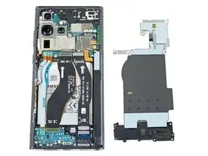
    • Grab and remove the NFC, wireless charging coil, and loudspeaker from the frame.

    • The wireless charging coil holds these parts together.

  24. XJDftpsGEpBocRqr
    XJDftpsGEpBocRqr
    G3YsXnQ6EhDARntr
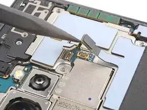
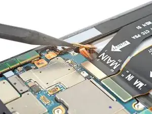
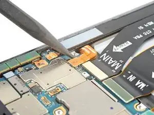
    • Use the pointed end of your spudger to pry up and disconnect the battery press connector.

Conclusion

To reassemble your device, follow these instructions in reverse order.
Clay Eickemeyer

Member since: 19/09/22

22501 Reputation

0 comments