
Introduction
Follow this guide to replace the screen and battery assembly on your Samsung Galaxy S22 Ultra with a genuine Samsung part.
This guide is written for the genuine Samsung screen and battery assembly. The assembly consists of the screen, battery, and frame together in one part. Be sure you have the right part before you begin the repair.
Before you begin, refer to the Samsung Self-Repair document for safety information.
If your battery is swollen, take appropriate precautions. Before disassembling your device, completely discharge the battery. This reduces the risk of a dangerous thermal event if the battery is accidentally damaged during the repair.
Note: Retaining water resistance after the repair will depend on how well you reapply the adhesive, but your device will lose its IP (Ingress Protection) rating.
-
-
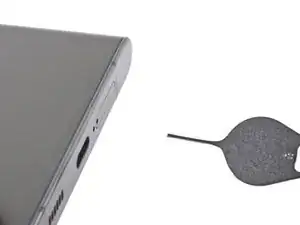
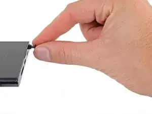
Insert a SIM eject tool, bit, or straightened paper clip into the SIM card tray hole on the bottom edge of the phone.
-
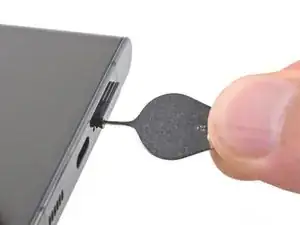
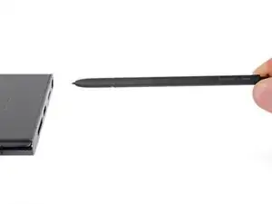
Press the SIM eject tool into the SIM card tray hole to eject the SIM card tray.
-
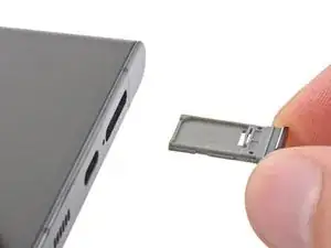
Remove the SIM card tray.
-
-
-
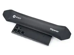
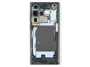
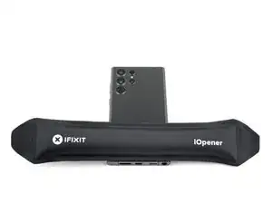
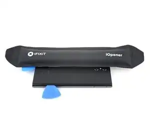
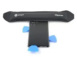
While you wait for the adhesive to soften, note the following:
-
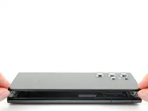
There's adhesive securing the back cover around the perimeter of the frame.
-
-
-
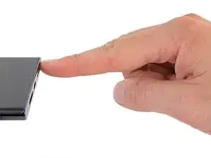
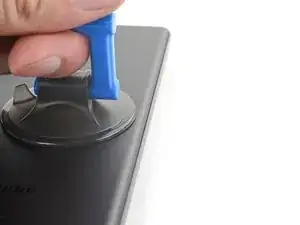
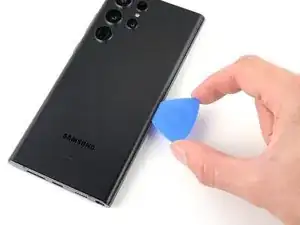
Apply a suction cup to the back cover, as close to the center of the right edge as possible.
-
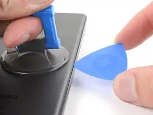
Pull up on the suction cup with strong, steady force to create a gap between the cover and the frame.
-
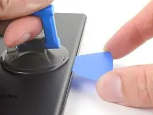
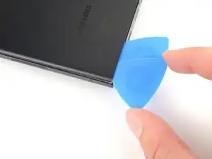
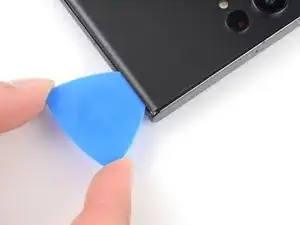
Insert an opening pick into the gap.
-
-
-
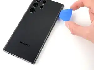
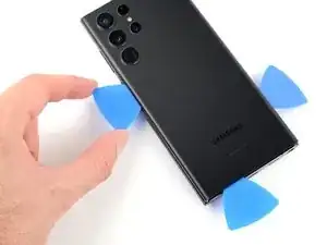
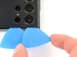
Slide the pick back and forth along the right edge to slice through the adhesive.
-
Leave the pick inserted near the bottom of the right edge to prevent the adhesive from resealing.
-
-
-
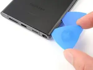
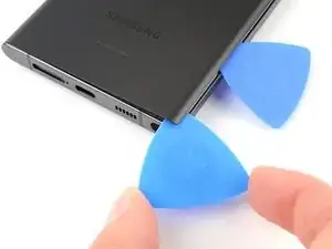
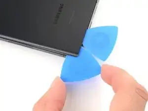
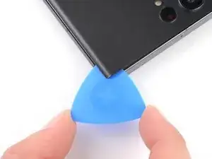
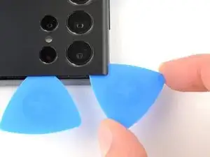
Insert a second opening pick at the bottom right corner.
-
Angle the pick upward to match the curved edge and rotate it around the bottom right corner.
-
-
-
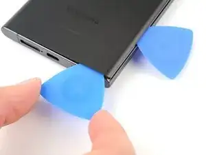
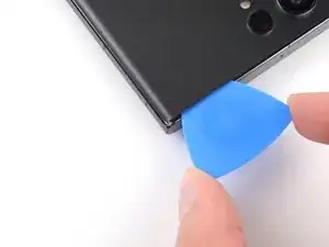
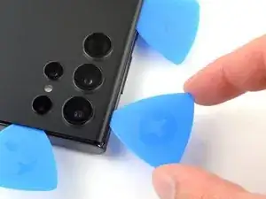
Slide your opening pick to the bottom left corner to slice the adhesive.
-
Leave the pick in the bottom left corner to prevent the adhesive from resealing.
-
-
-
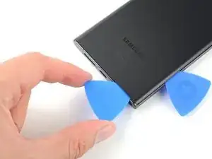
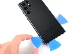
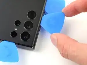
Insert a third opening pick at the bottom left corner.
-
Angle the pick upward to match the curved edge and rotate it around the bottom left corner.
-
-
-
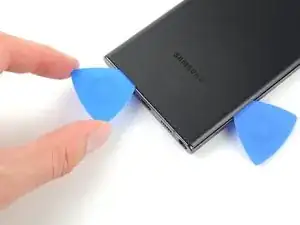
Slide your opening pick along the left edge to slice the adhesive, stopping when you reach the power button.
-
Leave the pick in the left edge to prevent the adhesive from resealing.
-
-
-
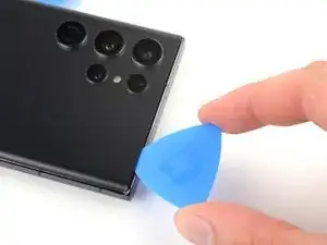
Insert an opening pick in the gap at the top right edge.
-
Angle the pick upward to match the curved edge and rotate it around the top right corner.
-
-
-
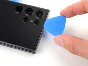
Slide the pick to the top left corner to slice the adhesive.
-
Leave the pick in to prevent the adhesive from resealing.
-
-
-
Insert an opening pick in the gap at the top left edge.
-
Angle the pick upward to match the curved edge and rotate it around the top left corner.
-
-
-
Slide the pick toward the bottom camera to slice through the remaining adhesive, stopping before you reach the power button.
-
-
-
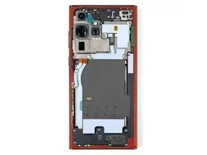
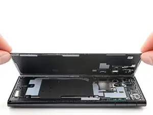
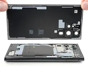
Grab and remove the back cover.
-
This is a good point to power on your phone and test all functions before sealing it up. Be sure to power your phone back down completely before you continue working.
-
Remove any adhesive chunks with a pair of tweezers or your fingers. Apply heat if you're having trouble separating the adhesive.
-
If you're using Samsung custom-cut adhesives, follow this guide.
-
If you're using double-sided tape, follow this guide.
-
-
-
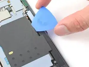
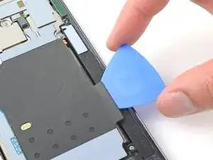
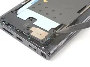
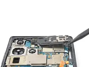
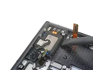
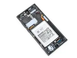
Insert an opening pick between the right edge of the wireless charging coil and the battery.
-
Slide the pick along the right edge to separate the adhesive.
-
-
-
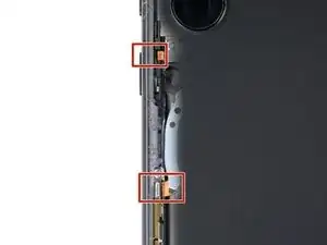
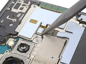
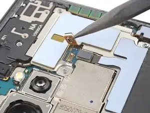
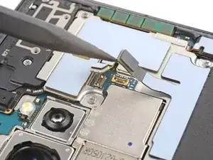
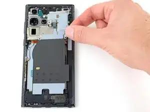
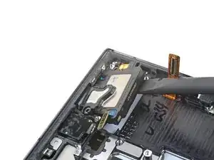
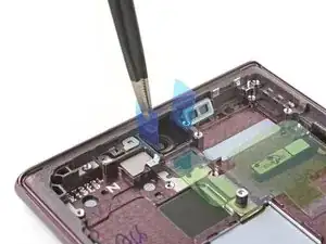
Use the pointed end of a spudger to pry and disconnect the NFC antenna press connector from the motherboard.
-
Repeat for the wireless charging coil press connector.
-
-
-
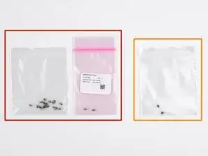
Label the bag with the most screws and the colored bag #3428.
-
If you're replacing the screen and battery, label the clear bag with two screws #3439.
-
-
-
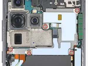
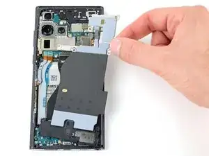
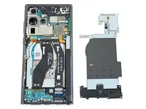
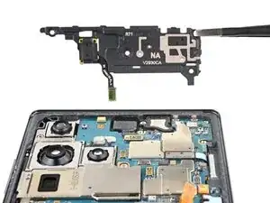
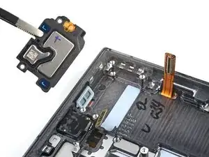
Use your Phillips screwdriver to remove the five 3.5 mm-long screws securing the NFC antenna and charging coil.
-
-
-
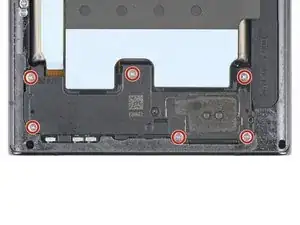
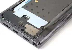
Insert the pointed end of your spudger between the upper right corner of the loudspeaker and the frame.
-
Pry up to unclip the loudspeaker from the frame.
-
-
-
Use the pointed end of your spudger to pry up and disconnect the lower 5G mmWave antenna press connector.
-
-
-
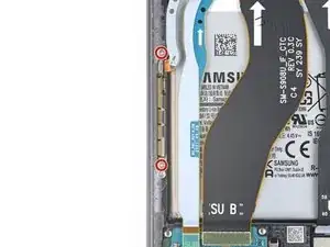
Use your Phillips screwdriver to remove the two 3.5 mm-long screws securing the antenna bracket.
-
-
-
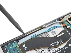
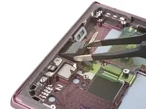
Insert the pointed end of your spudger between the lower screw mount of the antenna bracket and the frame.
-
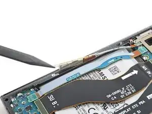
Pry up on the bracket until you can grab it with blunt nose tweezers or your fingers.
-
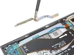
Remove the lower 5G mmWave antenna.
-
-
-
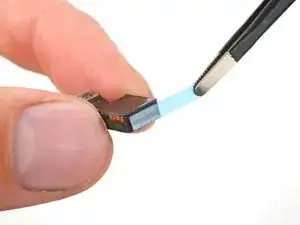
Remove the antenna and connector from the old bracket.
-
Remove the L-shaped adhesive liner from your new bracket.
-
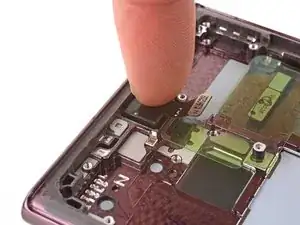
Place the antenna in the bracket's recess with the connector fed underneath the longer screw mount.
-
Remove the thin adhesive liner on the outside of the bracket before installing it in the frame.
-
-
-
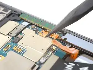
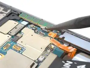
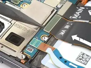
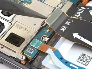
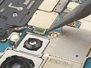
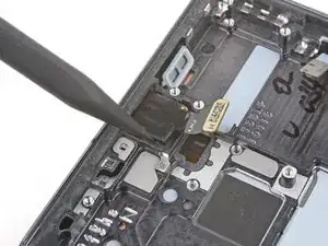
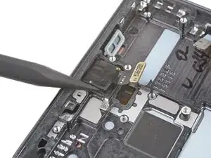
Use the pointed end of your spudger to pry up and disconnect the upper 5G mmWave antenna press connector.
-
-
-
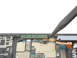
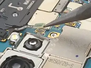
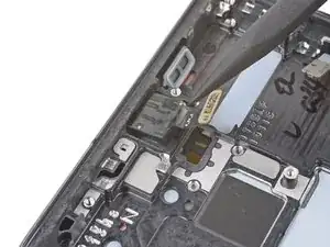
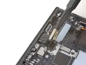
Insert the pointed end of your spudger in the gap between the bottom edge of the 5G mmWave antenna and the motherboard.
-
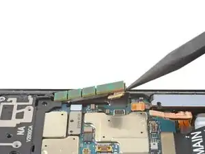
Pry the antenna out of its recess until you can grab it with your fingers or blunt nose tweezers.
-
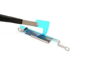
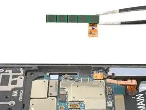
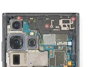
Remove the upper 5G mmWave antenna.
-
-
-
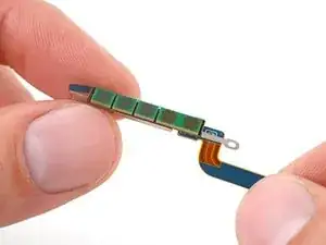
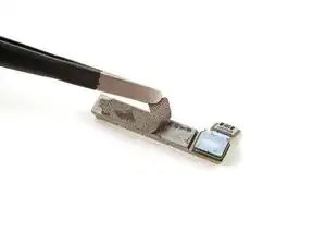
Remove the existing adhesive from the antenna with blunt nose tweezers or your fingers.
-
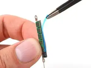
Remove the clear liner from your new adhesive.
-
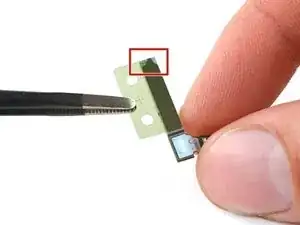
Apply the new adhesive to the bottom of the antenna, with its round end farthest from the connector.
-
Remove the green liner from the adhesive before reinstalling the antenna in the frame.
-
-
-
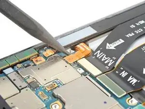
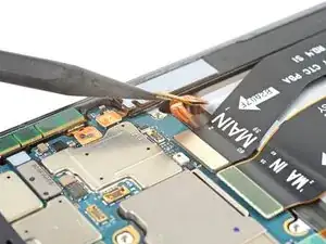
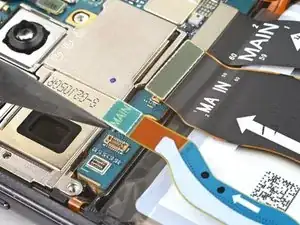
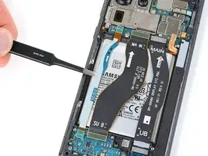
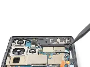
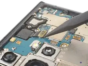
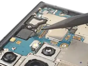
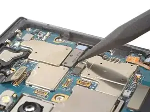
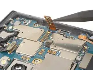
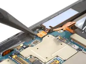
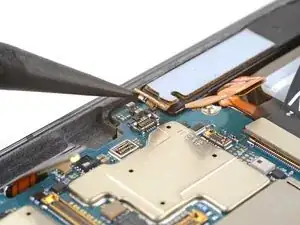
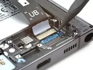
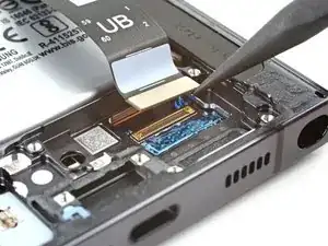
Use the pointed end of your spudger to pry up and disconnect the primary interconnect cable from the motherboard.
-
Repeat for the secondary interconnect located to the left of the primary cable.
-
-
-
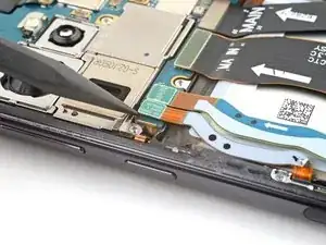
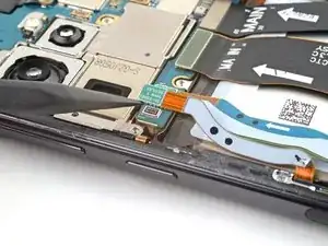
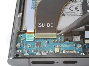
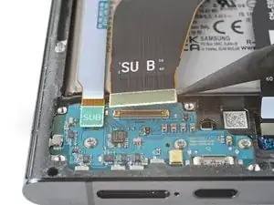
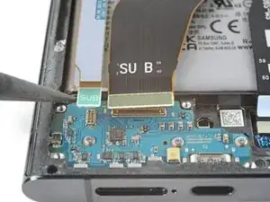
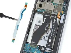
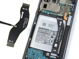
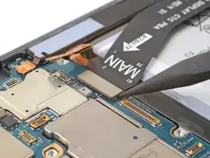
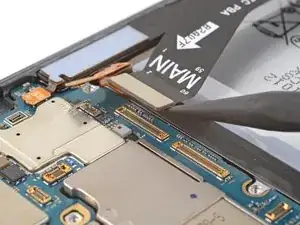
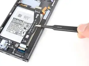
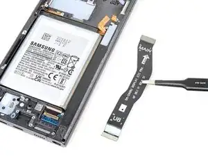
Use the pointed end of your spudger to pry up and disconnect the primary interconnect cable from the charging board.
-
Repeat for the secondary interconnect cable.
-
-
-
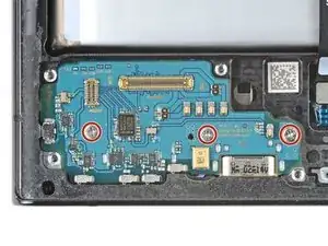
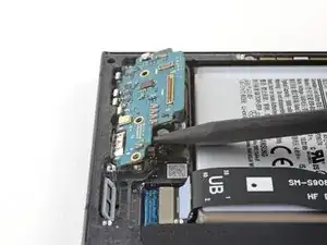
Use your Phillips screwdriver to remove the three 3.5 mm-long screws securing the charging board.
-
-
-
Insert the pointed end of your spudger under the charging board opposite the USB-C port.
-
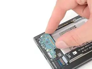
Pry the charging board up from its recess until you can grab it with your fingers.
-
-
-
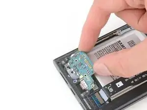
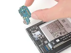
Grip the charging board by its corners and slide it out of its recess in the frame.
-
Remove the charging board.
-
-
-
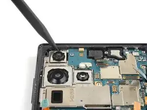
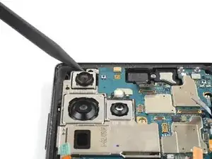
Use the pointed end of your spudger to pry up and disconnect the laser autofocus module press connector.
-
-
-
Use your Phillips screwdriver to remove the three 3.5 mm-long screws securing the motherboard cover.
-
-
-
Insert the pointed end of your spudger between the bottom right corner of the motherboard cover and the frame.
-
Pry up on the cover to unclip it from the frame.
-
Remove the motherboard cover and laser AF module.
-
-
-
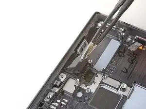
Use the pointed end of your spudger to pry up and disconnect the front-facing camera press connector.
-
-
-
Use the pointed end of your spudger to pry up and disconnect the fingerprint reader press connector.
-
-
-
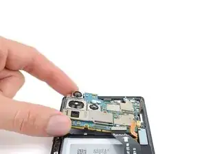
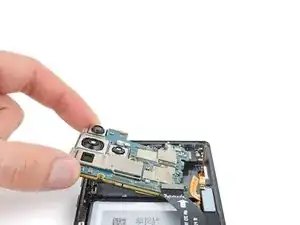
Insert the pointed end of your spudger between the top left of the motherboard and the frame.
-
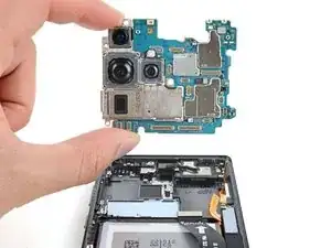
Pry the motherboard up until you can grab it with your fingers.
-
-
-
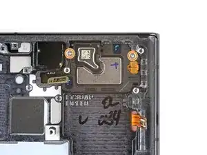
Use your Phillips screwdriver to remove the two 3.2 mm-long screws securing the earpiece speaker and vibration motor.
-
-
-
Insert the flat end of your spudger underneath the bottom edge of the earpiece speaker and vibration motor.
-
Pry the earpiece speaker and vibration motor up from its recess and remove it.
-
-
-
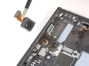
Use a pair of blunt nose tweezers to grab and remove the front-facing camera from its recess.
-
-
-
Remove the black adhesive liner from the front-facing camera recess.
-
Peel and remove the foam liner from the new frame.
-
-
-
Remove the two large clear rectangular liners from the adhesive sheet and place the adhesives on the sides of the camera recess.
-
Remove the liner from the main adhesive piece and place it in the center of the camera recess with its pull tab facing the bottom of the frame.
-
Remove any adhesive residue from the front-facing camera module.
-
Remove the liner from the thin piece of adhesive and place it on the top edge of the camera.
-
-
-
Remove all four blue adhesive liners from the camera and the frame.
-
Insert the front-facing camera into its recess in the frame and apply pressure to secure it.
-
-
-
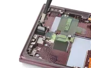
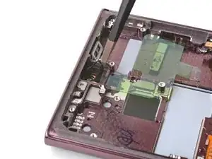
Use the pointed end of your spudger to pry up and disconnect the display cable press connector.
-


To reassemble your device, follow the instructions in reverse order and perform the opposite actions, e.g., "reattach" instead of "removing." Skip steps that use heating and prying, and pay close attention to the 📌 bullets as you work through the steps.
After you've completed the repair, download the Samsung Members App from the Galaxy Store or the Play Store, and Samsung Self-Repair document (beginning page 10) to make sure your device is fully functional.
Download the Self Repair Assistant on your device and Samsung Self-Repair document (beginning page 11) to perform a battery cycle reset.
Take your e-waste to an R2 or e-Stewards certified recycler.
Repair didn’t go as planned? Check out our Answers community for troubleshooting help.

6 comments
What about the adhesive when reassembling? Do I need to apply more? Or, does the original adhesive, reseal itself?
Hi! The Samsung Self Repair kit includes replacement adhesive to seal up the back cover. As mentioned in Step 18, follow this guide to clean your phone and apply the adhesive with an official replacement. If you don't have replacement adhesive, cut your own adhesive using double-sided tape, as described in this guide. Note that water resistance depends on how well you reapply your adhesive.
If you don't have access to either of these options, and your existing adhesive is in great condition, you may temporarily reuse the existing adhesive. I recommend shaping the adhesive exactly how it was before disassembly, and heating it with a heat gun or hair dryer to soften it before installing your back cover. Exercise caution when heating the phone, and follow this guide as a reference for heating your device.
So I have a stupid question but I was told that if you had a different color phone that the Amoled screen had to match the casing of the phone or it would affect the effectiveness of the screen and the calibration. This sounds so incredibly stupid to me but is this true?
Anything regarding part compatibility is important to us. May I ask where you heard this, and in what context? My initial reaction is that the screens are compatible, since there is no calibration software, anyway. There is only fingerprint sensor calibration.
Been following this guide and unfortunately the replacement screen with frame I got has a different bracket for the Upper 5mm wave antenna, so it doesn't fit back into it. The new one has a little bump out in the middle of the silver bracket (and the molded frame itself). The old one is as pictured here in the guide. The antenna part has a perfectly straight edge, so there's no way to get it in to fit. Any ideas?
Mike W -
Figured it out - to anyone reading this! The 5mmWave radio is different in the Intl models vs the USA "U" models and the frame has a different molding and the aren't compatible! I ordered a replacement screen and frame, from a reputable US vendor, listed as the U model and all the packaging too- and it wasn't. You'll see various parts listed all over online for sale that says 908U or 908B/E interchangeable. They are not! The shell is different so the upper radio antenna doesn't fit and it's impossible to make it fit. You need to make sure you're truly getting the U model frame with any replacement screen.
Mike W -