
Introduction
Prerequisite-only guide to replace the logic board assembly in an iMac 27" 2017.
-
-
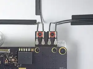
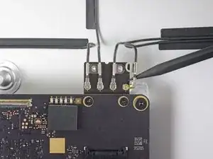
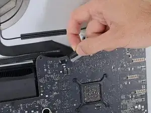
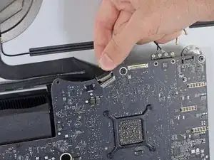
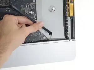
Use a T5 Torx screwdriver to remove the two 4 mm screws securing the AirPort/Bluetooth antenna cables.
-
-
-
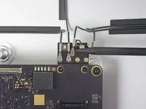
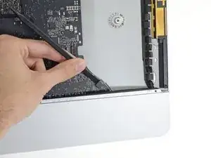
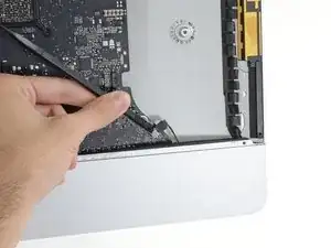
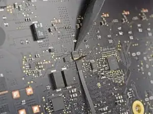
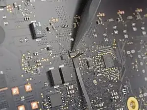
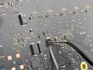
Use the point of a spudger to disconnect each of the four antenna connectors from the AirPort/Bluetooth card.
-
Leftmost
-
Top
-
Upper right
-
Lower right
-
-
-
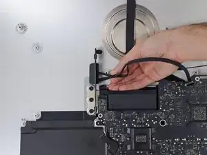
Flip up the metal retaining bracket on the iSight camera cable.
-
Pull the camera cable connector straight out of its socket, toward the top of the iMac.
-
-
-
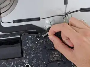
Use the flat end of a spudger to disconnect the headphone jack cable connector from its socket on the logic board.
-
Gently push the cable out of the way.
-
-
-
Use the tip of a spudger to flip open the retaining flap on the microphone ribbon cable ZIF socket.
-
Use tweezers to gently pull the microphone ribbon cable straight out of its socket.
-
-
-
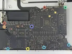
Remove the following screws securing the logic board:
-
Two 23.7 mm T8 screws
-
One 20.1 mm T25 spacer screw
-
One 17.6 mm T8 screw
-
One 7.2 mm T8 screw
-
Three 7.1 mm T8 screws
-
One captive T8 screw
-
-
-
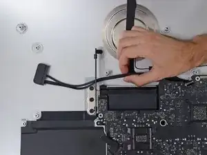
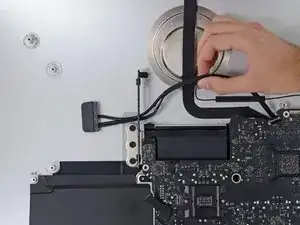
Pull the hard drive SATA cable and connector through the right hard drive bracket. Move the cable to the right side of the iMac, out of the way of the exhaust port.
-
-
-
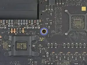
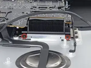
Use a T8 Torx screwdriver to remove the two 5.6 mm screws from the top of the heat sink exhaust duct.
-
-
-
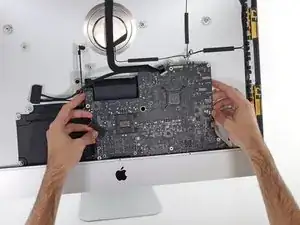
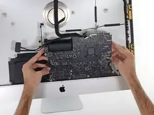
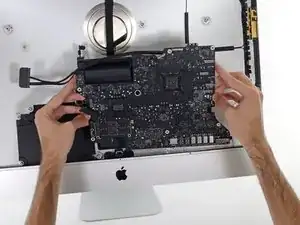
Tilt the logic board slightly forward.
-
Lift the logic board straight up and out of the iMac. Be careful not to snag it on any of the screw posts attached to the inside of the rear case.
-
-
-
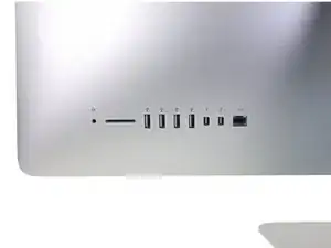
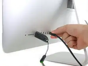
When reassembling your iMac, be very careful to align the exterior I/O ports correctly. The logic board can sit crooked even when secured with all its screws.
-
You can use a USB flashdrive or ethernet cable to ensure the logic board is seated correctly while you screw it in.
-

To reassemble your device, follow these instructions in reverse order.

Rather than unscrew the antenna cables, I usually unscrew the screws on the board and slide out the whole AirPort/Bluetooth module, which means I need not keep track of which antenna cable goes where.
johann beda -
Confirmed. 2 T5 screws, and pull the board straight up out of its socket behind he motherboard. Leave all cables attached.
ebay -