Introduction
Follow the steps in this guide to replace the logic board in an iPad 5 LTE.
Note that replacing the logic board will result in losing all your data, as well as Touch ID functionality.
Parts of this guide were shot with a Wi-Fi model and as such the internals may look slightly different from the LTE model. The procedure is the same for both models except where noted.
-
-
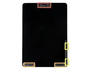
While you're waiting for the adhesive to loosen, note the following areas that are sensitive to prying:
-
Front camera
-
Antennas
-
Display cables
-
-
-
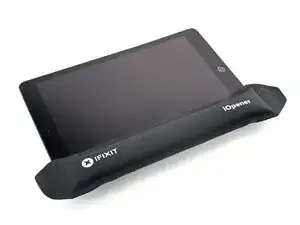
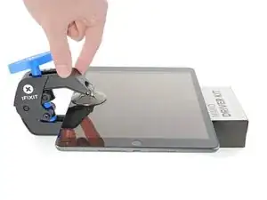
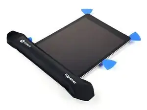
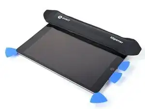
Elevate the iPad enough for the Anti-Clamp's arms to rest above and below the screen.
-
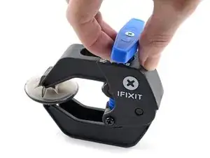
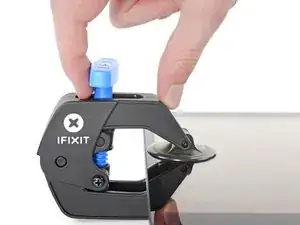
Pull the blue handle towards the hinge to disengage opening mode.
-
Position the suction cups near the left edge of the iPad—one on the front, and one on the back.
-
Push down on the cups to apply suction to the desired area.
-
-
-
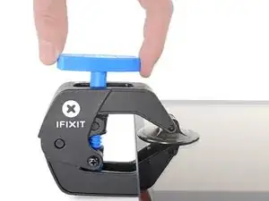
Push the blue handle away from the hinge to engage opening mode.
-
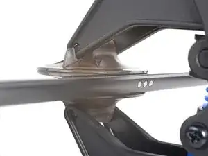
Turn the handle clockwise until you see the cups start to stretch.
-
Wait one minute to give the adhesive a chance to release and present an opening gap.
-
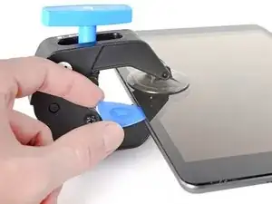
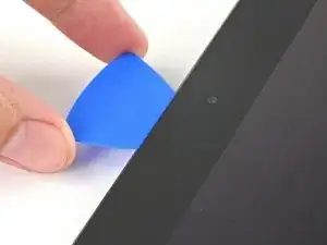
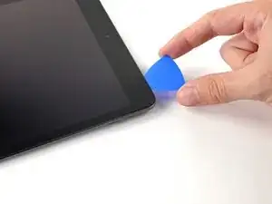
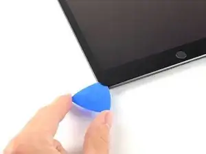
Insert an opening pick under the digitizer when the Anti-Clamp creates a large enough gap.
-
Skip the next step.
-
-
-
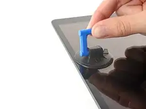
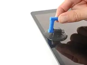
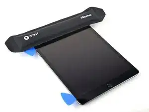
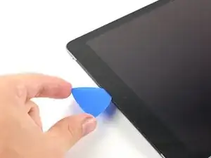
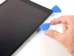
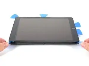
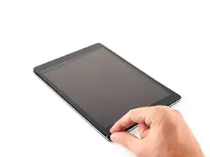
Once the screen is warm to touch, apply a suction handle to the left edge of the screen and as close to the edge as possible.
-
Lift the screen with the suction handle to create a small gap between the digitizer and the frame.
-
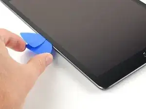
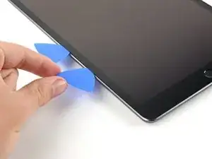
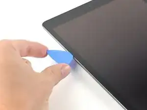
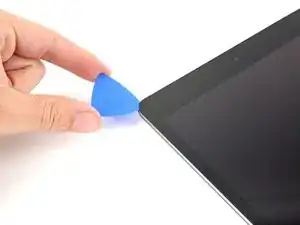
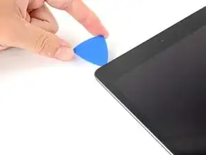
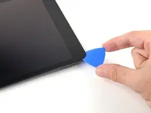
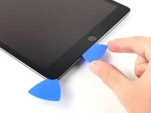
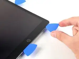
Insert an opening pick into the gap between the digitizer and the frame.
-
-
-
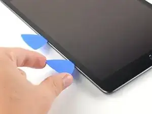
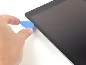
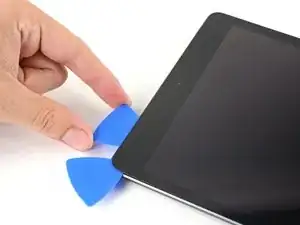
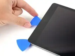
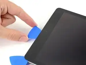
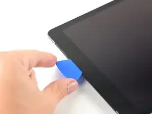
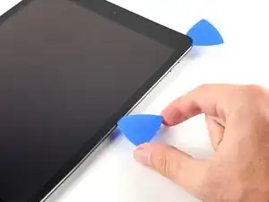
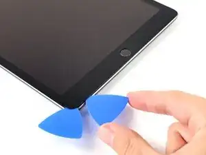
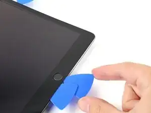
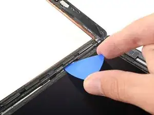
Insert a second opening pick into the gap you just created.
-
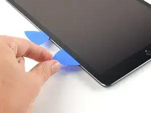
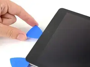
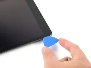
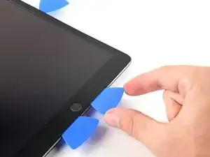
Slide the pick toward the bottom-left corner of the device to separate the adhesive.
-
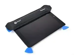
Leave the pick in the bottom-left corner to prevent the adhesive from re-sealing.
-
-
-
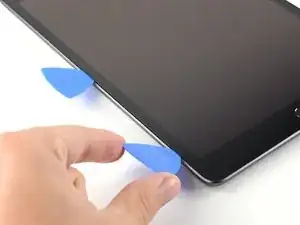
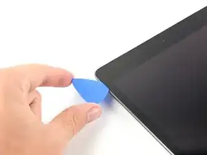
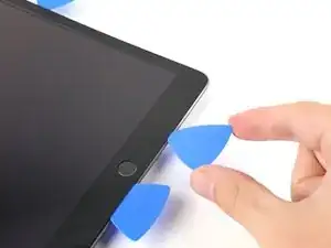
If the opening pick gets stuck in the adhesive, "roll" the pick along the side of the iPad to continue separating the adhesive.
-
-
-
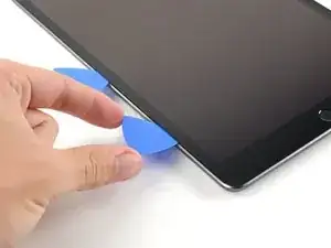
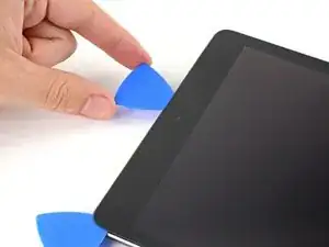
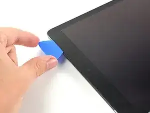
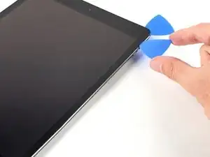
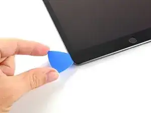
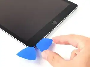
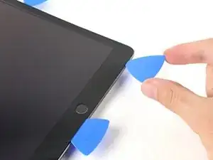
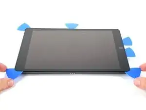
Slide the first opening pick towards the top-left corner of the device to separate the adhesive.
-
Leave the pick in the top-left corner to prevent the adhesive from re-sealing.
-
-
-
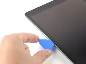
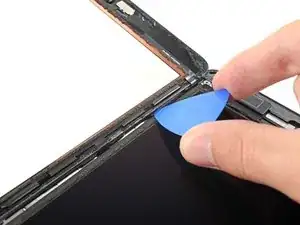
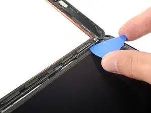
Slide the opening pick along the top edge of the device, stopping just before you reach the front camera.
-
-
-
Pull the pick out until only the tip is between the digitizer and the frame.
-
Slide the pick above the front camera to separate the adhesive.
-
Leave the pick near the right side of the front camera before continuing.
-
-
-
Re-insert the pick and slide it towards the top-right corner of the device to completely separate the top adhesive.
-
Leave the pick in the top-right corner to prevent the adhesive from re-sealing.
-
-
-
Slide the bottom-left pick to the bottom-left corner to separate the adhesive.
-
Leave the pick in the bottom-left corner before moving to the next step.
-
-
-
Insert a new opening pick into the gap you just created on the bottom edge of the iPad.
-
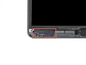
Slide the pick over the antenna, stopping just before the home button.
-
Leave the pick to the left of the home button before continuing.
-
-
-
Insert an opening pick into the gap you just created.
-
Slide the pick underneath the home button and towards the bottom-right corner, making sure only the tip is between the digitizer and the frame.
-
-
-
Re-insert the pick and slide it towards the home button to completely separate the bottom adhesive.
-
Leave the pick to the right of the home button before continuing.
-
-
-
Twist the two opening picks on the left corners of the iPad to lift the digitizer slightly, separating the the last of the adhesive in the process.
-
-
-
Lift the left edge of the digitizer upwards to further separate the adhesive along the right edge of the iPad.
-
-
-
While supporting the digitizer, slide an opening pick between the two display cables to separate the last of the adhesive.
-
-
-
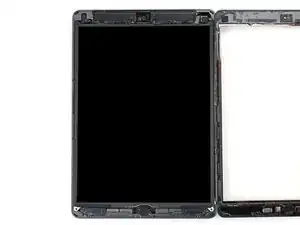
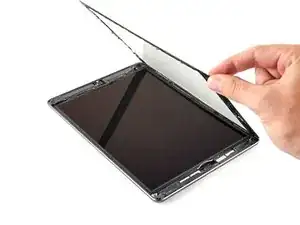
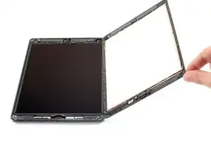
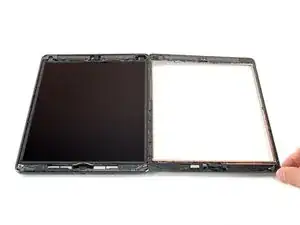
Once all of the adhesive has been separated, open the digitizer like a book and rest it parallel to the iPad.
-
-
-
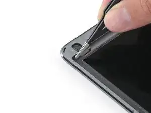
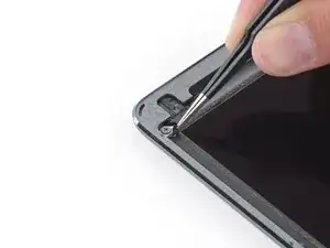
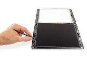
Use the flat end of a spudger to pry the LCD out of its recess just enough to grab it with your fingers.
-
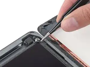
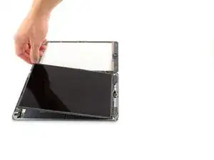
Flip the iPad LCD like a page in a book, lifting near the camera and turning it over the home button end of the rear case.
-
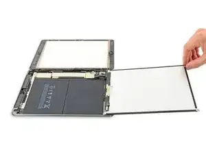
Lay the LCD on its face to allow access to the display cables.
-
-
-
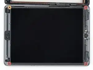
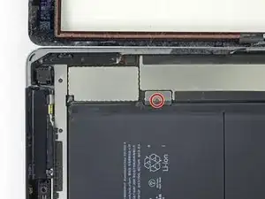
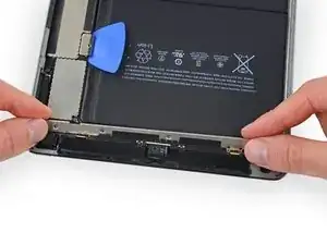
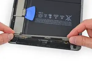
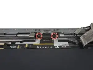
Remove the single 2.3 mm Phillips screw securing the battery connector to the logic board.
-
Leave the blocker there to prevent the battery connector leads from making contact until you have completed your repairs.
-
-
-
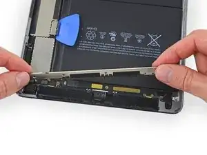
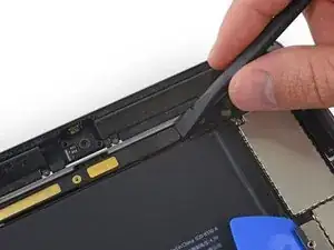
Use the flat end of a spudger to gently pry the display cable bracket straight up from the logic board.
-
-
-
Use the flat end of a spudger to flip the tab on the home button ribbon cable ZIF connector upward.
-
Carefully pull the home button ribbon cable straight out of the ZIF connector.
-
-
-
Use the flat end of a spudger or a fingernail to carefully pop the two digitizer cable connectors straight up from their sockets.
-
-
-
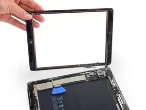
Remove the front panel assembly.
-
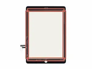
If you experience "ghost" or "phantom" touch input issues with your new display, this can be resolved by adding a layer of very thin insulating tape, such as Kapton (polyimide) tape, to the highlighted areas on the back of the panel. iFixit panels come with the proper insulation, and should not require the addition of any tape.
-
-
-
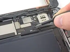
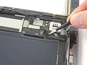
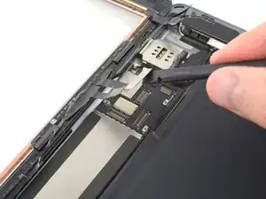
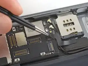
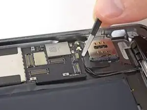
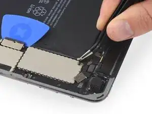
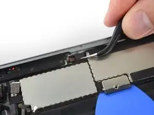
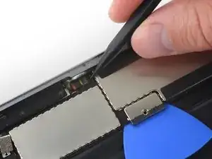
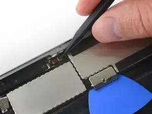
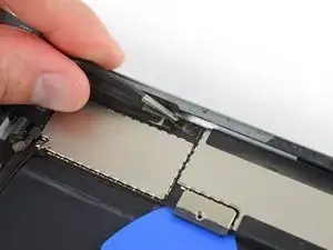
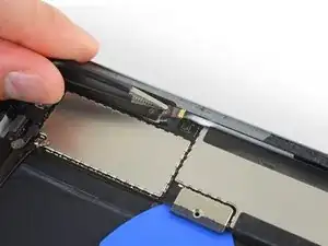
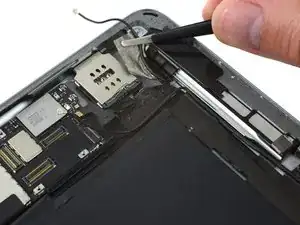
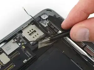
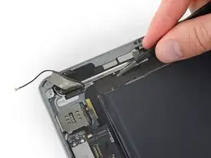
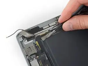
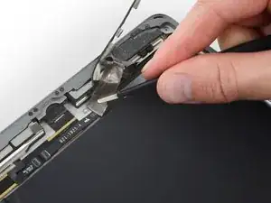
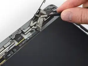
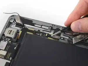
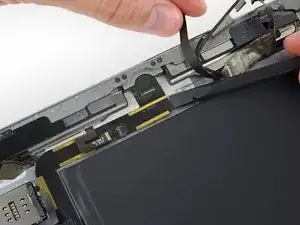
Use tweezers to peel and remove the piece of tape covering the SIM board cable connector on the logic board.
-
-
-
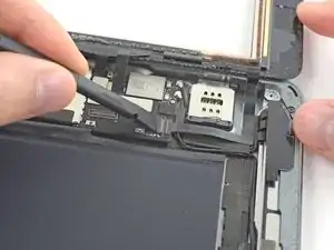
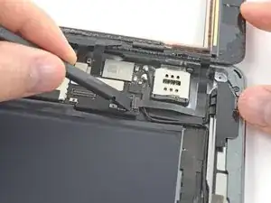
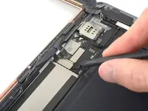
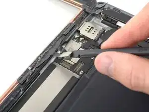
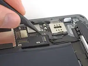
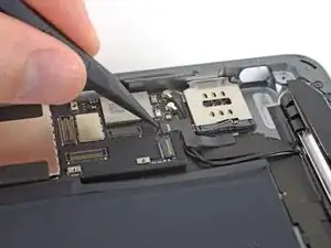
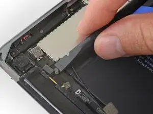
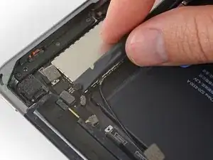
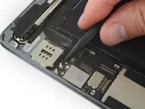
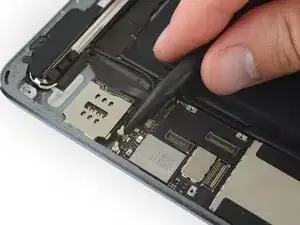
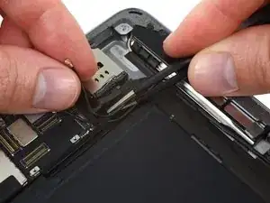
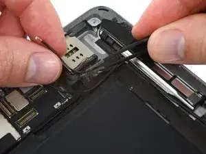
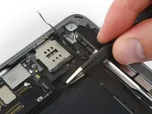
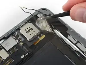
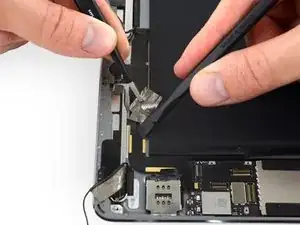
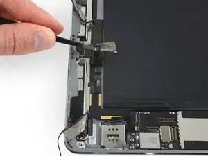
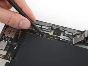
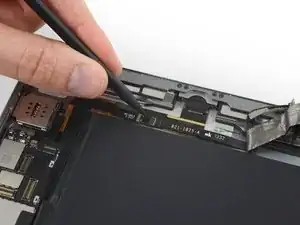
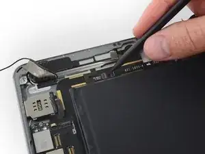
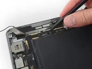
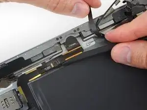
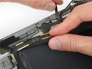
Use the pointed end of a spudger to flip up the retaining flap on the SIM board cable connector.
-
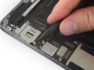
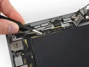
Slide the SIM board cable straight out of its ZIF connector.
-
-
-
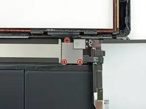
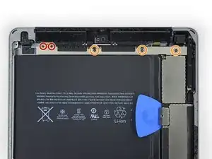
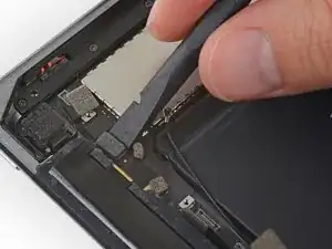
Remove the following screws securing the upper component cable bracket:
-
Two 2.0 mm Phillips screws
-
Three 1.4 mm Phillips screws
-
-
-
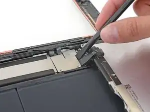
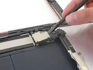
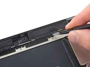
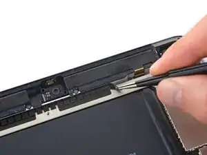
Slowly peel the upper component cable bracket up out of the iPad—leaving the tape pieces on the bracket to make it easier to reinstall.
-
-
-
Use the flat end of a spudger to disconnect the front-facing camera connector from its socket on the logic board.
-
-
-
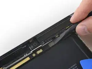
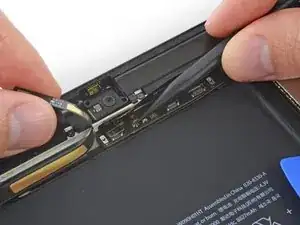
Slide an opening pick underneath the front-facing camera cable to break up the adhesive holding it in place.
-
Push the camera cable up with a spudger to reveal a second ribbon cable connector underneath.
-
-
-
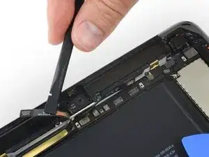
Use the flat end of a spudger to gently disconnect the headphone jack ribbon cable from its socket on the logic board.
-
Again, carefully push this second ribbon cable aside to reveal more connectors underneath.
-
-
-
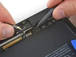
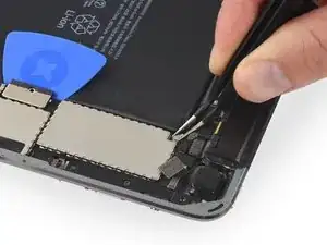
Use the pointed tip of a spudger to disconnect the microphone cable connector from its socket on the logic board.
-
Use the pointed tip of the spudger to disconnect the GPS antenna cable, directly to the right of the microphone cable connector.
-
-
-
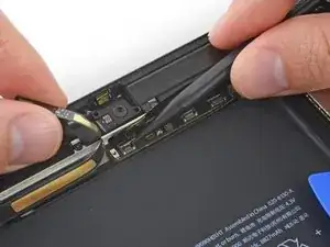
Use the flat tip of a spudger to disconnect the rear-facing camera cable by prying it straight up from its socket on the logic board.
-
-
-
Disconnect the antenna interconnect cable by lifting it straight up from its socket on the logic board.
-
-
-
Use the flat end of a spudger to disconnect the primary cellular antenna interconnect cable from its socket on the logic board.
-
-
-
Use the flat end of a spudger to lift the primary cellular antenna connector from its socket on the logic board.
-
-
-
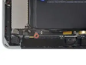
Remove the 1.4 mm Phillips screw securing the primary cellular antenna interconnect cable bracket.
-
-
-
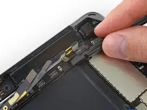
Use the flat end of a spudger to gently fold the primary cellular antenna interconnect cable bracket up and out of the way.
-
-
-
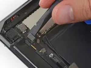
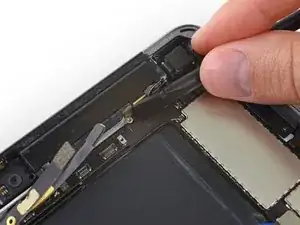
Use the pointed tip of a spudger to flip up the retaining flap on the upper button assembly cable connector.
-
-
-
Use tweezers to carefully pull the upper button assembly ribbon cable straight out of its connector.
-
-
-
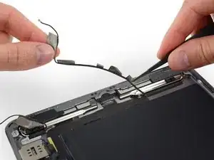
Disconnect the left and right Wi-Fi antenna cables by lifting them straight up from their sockets on the lower end of the logic board.
-
-
-
Use a pair of tweezers to peel up the tape securing the right Wi-Fi antenna cable near the SIM board.
-
-
-
Repeat the previous step to peel up a second piece of tape directly underneath, securing the left Wi-Fi antenna cable.
-
If you accidentally peeled up both pieces of tape together, carefully peel them apart and separate them before proceeding to the next step.
-
-
-
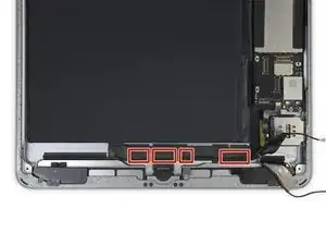
Four additional pieces of tape secure the left Wi-Fi antenna near the lower edge of the iPad.
-
Peel the tape up from the rear case.
-
Fold the antenna cable out of the way.
-
-
-
Instead, grip the tape just under the speaker and peel it down, away from the edge of the case.
-
-
-
Continue peeling up the tape away until there is enough slack in the left speaker cable to disconnect it.
-
-
-
Use the pointed end of a spudger to flip up the retaining flap on the left speaker cable connector.
-
Disconnect the left speaker cable by pulling it straight out of its socket.
-
-
-
Use the pointed end of a spudger to flip up the retaining flap on the right speaker cable connector.
-
Disconnect the right speaker cable by pulling it straight out of its socket.
-
-
-
The adhesive is in the form of seven strips of black tape—refer to this step as you work at heating and prying to keep track of where each piece is located.
-
-
-
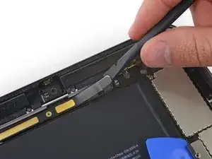
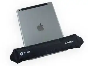
Reheat your iOpener and lay it over the bottom edge of the iPad to soften the adhesive securing the Lightning port ribbon cable to the rear case.
-
Wait a couple minutes for the adhesive to soften, then move on to the next step.
-
-
-
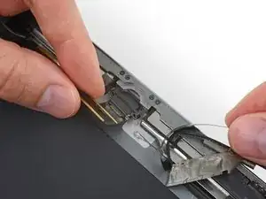
Slide the flat end of a spudger under the Lightning connector cable to break up the adhesive securing it to the rear case.
-
If necessary, push the left speaker cable gently aside to provide access to the Lightning connector cable.
-
-
-
Lay a warm iOpener over the upper edge of the iPad and let it sit for a couple minutes to soften the adhesive holding the logic board in place.
-
-
-
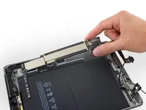
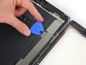
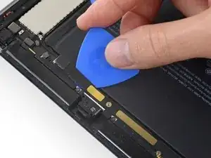
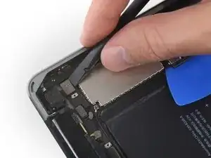
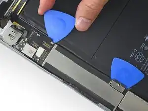
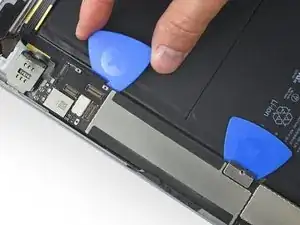
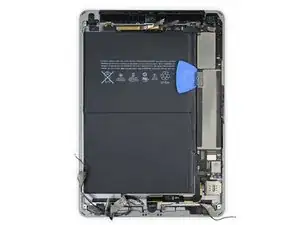
Carefully insert an opening pick under the logic board, between the front-facing camera and the battery.
-
Slide the guitar pick toward the front-facing camera connector, and stop at the bend in the logic board.
-
-
-
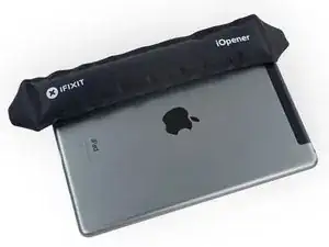
Reheat your iOpener and lay it lengthways on the rear case, directly over the logic board.
-
Wait a couple minutes for the adhesive to soften, then remove the iOpener and move on to the next step.
-
-
-
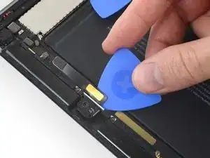
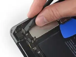
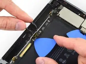
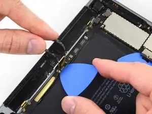
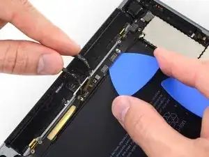
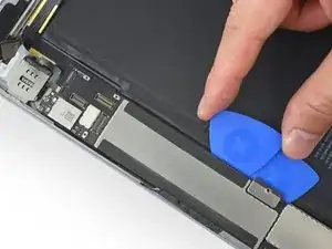
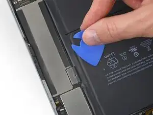
Insert an opening pick underneath the logic board at the corner of the large EMI shield.
-
Slide the pick upwards until you reach the battery connector to break up the adhesive holding the logic board in place.
-
-
-
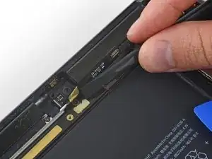
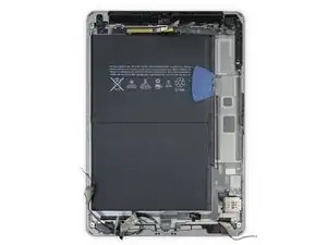
Remove the battery isolation pick.
-
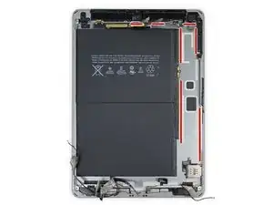
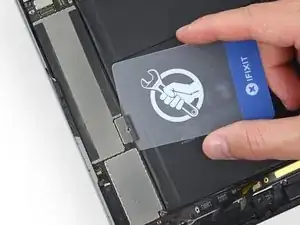
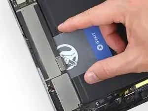
Insert a plastic card underneath the logic board at the battery connector.
-
Slide the card all the way underneath the logic board, separating the adhesive along the outer edge.
-
-
-
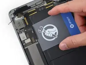
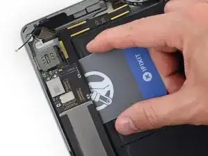
Insert a plastic card underneath the lower end of the logic board, directly underneath the display connectors and Wi-Fi module.
-


To reassemble your device, follow these instructions in reverse order.