Einleitung

The motherboard is the central hub of all of the internal components in a device. All other components in a device send signals to the motherboard, and the motherboard is usually one of the last components to fail in a device (barring unforeseen circumstances). The following symptoms can be signs of a failing motherboard:

  • Blue screen of death (BSoD)
  • Laptop is running very slow
  • Laptop isn’t booting up properly
  • Laptop keeps freezing
  • Other components aren’t being recognized

If your Lenovo ThinkPad T450 is exhibiting any of the above symptoms, it may be time to replace the motherboard in your device. Follow these instructions to replace the motherboard in your laptop.

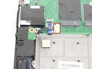
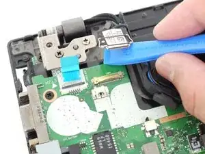
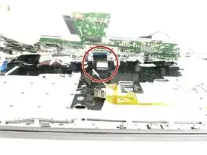
Please make sure to disconnect the ZIF connector from the motherboard prior to fully removing it from the device. You can find more information in the third image of step 27.

  1. GcEgrjAYTtgvMrJU
    GcEgrjAYTtgvMrJU
    qjQnqBoMZgCExG6c
    AUOQYlJw3tssVPZ6
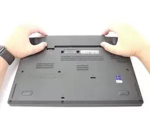
    • Using your hands, slide the two locking tabs away from each other to release the battery.

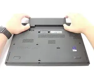
    • Slide the battery up and out of the device.

  2. kwDDPHTuMOwKALEQ
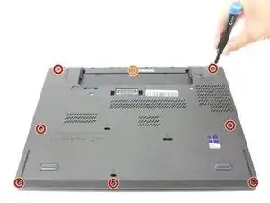
    • Using the JIS #00 screwdriver, unscrew seven screws from the back cover.

    • These screws are not removable and will remain in the back cover.

    • Use the JIS #00 screwdriver to remove the single 2.8 mm screw from the back cover.

  3. kU4HR61EuVejlInR
    kU4HR61EuVejlInR
    KEUfVEn5PG6RJFLs
    YS3EHvoewHpZjH3b
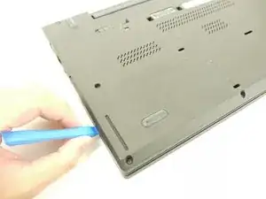
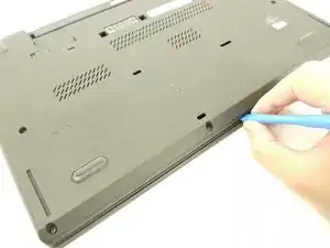
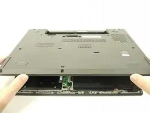
    • Insert a plastic opening tool into the edges of the laptop and work your way around the edges to pry off the back cover from the device.

    • Remove the back cover from the device.

  4. S4EplWfuNee2Tnro
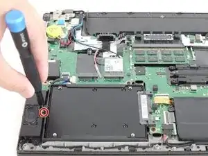
    • Using the JIS #00 screwdriver, remove the single 2.8 mm screw securing the SSD to the device.

  5. DRYUuVWBpkVIFcm4
    DRYUuVWBpkVIFcm4
    1HWVubFOXvRWWrPF
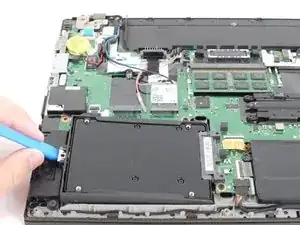
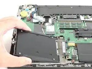
    • Lift the SSD up and to the left and remove it from the device.

  6. CThlc1MhpFrQLQQH
    CThlc1MhpFrQLQQH
    ZyCCHjES63qgavWP
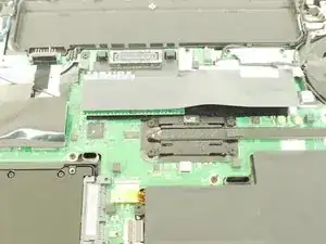
    • Lift up the black piece of tape and remove it to uncover the RAM sticks underneath.

  7. MauMP3nqiUMHHedK
    MauMP3nqiUMHHedK
    AuYHH1QvhtKGeWcH
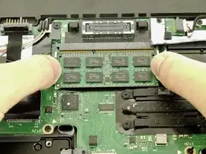
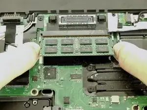
    • Using your fingers, push the two clips securing the RAM away from each other to release the RAM.

    • The RAM stick should pop up at a 30 degree angle.

    • Remove the RAM stick from the device.

    • Repeat this step for any additional RAM sticks.

  8. FOin4BAWPDbnyjma
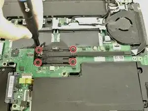
    • Using the JIS #00 screwdriver, unscrew the four screws securing the fan and heatsink assembly to the motherboard.

    • These screws are not removable and will stay on the fan and heatsink assembly.

  9. QnbtsrmSdjvCA1RL
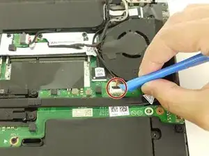
    • Disconnect the fan and heatsink assembly from the motherboard using the plastic opening tool.

  10. ocNRGxbLNFSbOh4y
    ocNRGxbLNFSbOh4y
    klPmmcJpHp5i2OXJ
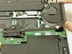
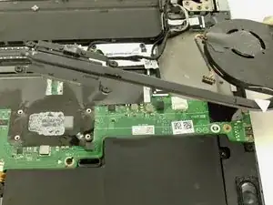
    • Lift up the fan and heatsink assembly and remove it from the device.

    • When you reassemble your device, don't forget to reapply thermal paste to the back of the heatsink and fan assembly. For proper technique and thermal paste application, please visit the How to Apply Thermal Paste guide.

  11. LusNY3siLFTAkmtN
    • Lift and remove the black piece of plastic to expose the Wi-Fi card.

  12. WMTHpITD6tuppAU6
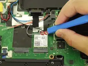
    • Using the plastic opening tool, disconnect the two cables from the Wi-Fi card.

  13. Ok1MIQlOAZQQBYAO
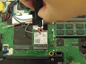
    • Using the JIS #00 screwdriver, remove the single 2.8 mm screw.

    • After removing the screw, the Wi-Fi card should pop up on its own.

  14. of3pQvcVWJCPlH6I
    of3pQvcVWJCPlH6I
    1DwIj6e3SheaGPPZ
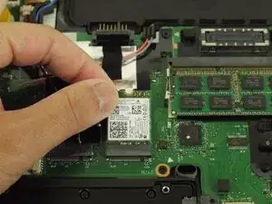
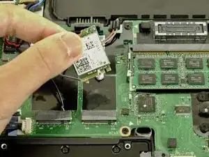
    • Lift the Wi-Fi card out of the slot and remove it from the device.

    Not to be Captain Semi-Obvious... but can you tell us the model of the wi-fi lan card? I am getting in my possession a t450 with wifi not working.. I have yet to look at machine to see if it is in fact a bad card.. but would like to be able to factor such cost into my purchase. I hope you see this relatively soon, as I have a Top Shelf bottle of ketchup for you if you reply soon!! Thanks

    Andre -

  15. tUMPuGLaLOJCAvNa
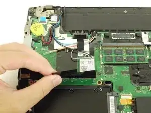
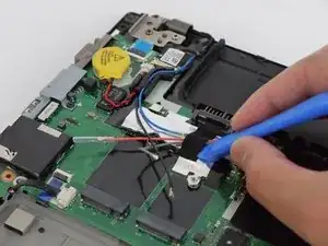
    • Use the plastic opening tool to remove the black piece of tape holding the cables together.

  16. ZJcDIConQ5bZM5Yc
    ZJcDIConQ5bZM5Yc
    ehiLHXNTQZeTSwFh
    • Use the JIS #00 screwdriver to remove the single 2.8 mm screw from the motherboard.

    • Remove the black plastic covering the motherboard.

  17. iHXRRGqydLrqPDSU
    iHXRRGqydLrqPDSU
    gyAnm1Gvtp2rxpm5
    xm2ltfxcaGb2ClRc
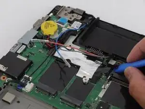
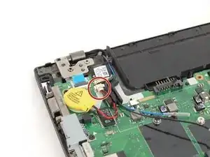
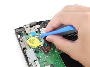
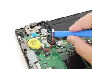
    • Using the plastic opening tool, disconnect the CMOS battery from the motherboard.

  18. 1yYqaqZx5KeQvF3S
    1yYqaqZx5KeQvF3S
    YiY1VBftOV5Mdk1L
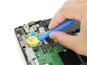
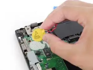
    • Insert the plastic opening tool underneath the CMOS battery and pry it up and away from the motherboard.

    • When you reassemble your device, you may need to reapply adhesive to the back of the CMOS battery.

  19. oPTeROVe2Bl6lPeE
    oPTeROVe2Bl6lPeE
    L5gkMrMRTDCYEVuW
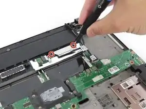
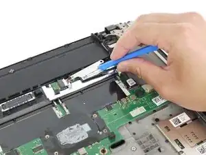
    • Use the JIS #00 screwdriver to remove two 2.8 mm screws securing the display cable bracket to the motherboard.

    • Remove the display cable bracket from the device.

  20. LVQsRXMDsmpMaWUL
    LVQsRXMDsmpMaWUL
    djE14JjN3GjbKatS
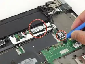
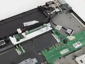
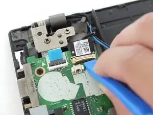
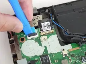
    • Disconnect the daughterboard cable and the display cable using the plastic opening tool.

  21. 2yTT3FnKyWTj2JLi
    2yTT3FnKyWTj2JLi
    A2JxZMvS51GTnlHT
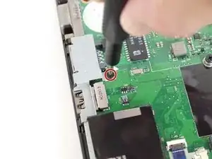
    • Using the JIS #00 screwdriver, remove the single 5 mm screw securing the bracket to the motherboard.

    • Remove the metal bracket from the device.

  22. xCX1SMJbUdbjCLgS
    xCX1SMJbUdbjCLgS
    562d5BedeEXGMBZX
    • Disconnect the speaker cable from the motherboard using the plastic opening tool.

  23. OTopYehMP4AZV6kt
    OTopYehMP4AZV6kt
    KRrRwWRDdTrfoSWv
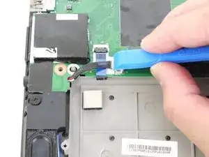
    • Using the plastic opening tool, flip up the locking tab on the zero insertion force (ZIF) connector and disconnect the cable from the motherboard.

    • For more information on different types of cables and connectors, please visit the Recognizing & Disconnect Cable Connectors guide.

  24. XZWLXyfZaJf6AwDY
    XZWLXyfZaJf6AwDY
    qXQMacSpKpO3rrN1
    uAbeZpErSDBAtFd6
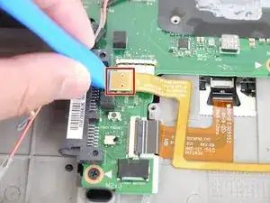
    • Using the plastic opening tool, disconnect the CMOS and power cables.

    • The power cable is a zero insertion force (ZIF) connector. For more information on disconnecting ZIF connectors, please visit the Recognizing & Disconnecting Cable Connectors guide.

  25. qVttrP1W3GfBujg3
    qVttrP1W3GfBujg3
    5ouRjOisngCGnPTj
    2YCENyicZbMOY4sA
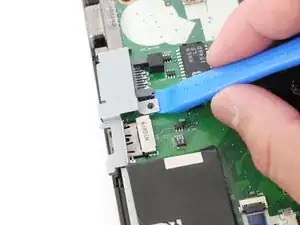
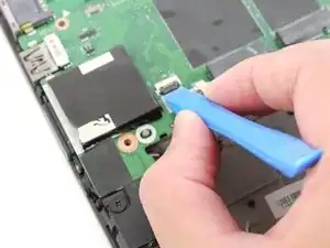
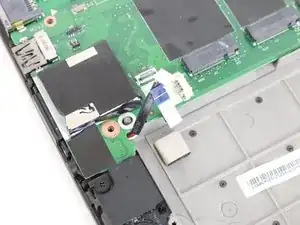
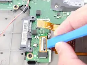
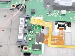
    • Using a plastic opening tool, disconnect the smartcard reader cable from the motherboard.

    • Using the same plastic opening tool, flip up the locking tab and disconnect the trackpad cable from the motherboard.

  26. DX4EAle2JSRpSZnt
    DX4EAle2JSRpSZnt
    p1RcMaWL2pqEX4vk
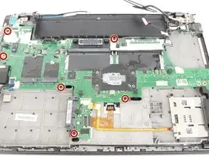
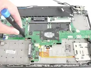
    • Using the JIS #00 screwdriver, remove six 2.8 mm screws securing the motherboard to the device.

  27. khn1NyVFKGbXLwl4
    khn1NyVFKGbXLwl4
    kupk5wHOvaGGKCur
    QWjiJlJ2LbGBaUsE
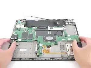
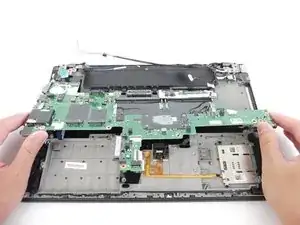
    • Carefully grab the motherboard and lift it up slightly off of the device.

    • Do not completely remove the motherboard from the device. There is a zero insertion force (ZIF) connector underneath the motherboard.

    • Disconnect the ZIF connector and remove the motherboard from the device.

    • For more information on zero insertion force (ZIF) connectors, please visit the Recognizing and Disconnecting Cable Connectors guide.

    I recently needed to replace the motherboard in my ThinkPad T450 Type 20BV - on boot up after the Lenovo screen it comes up with the following error message "2200 Machine type and serial number are invalid" and then boots into Windows and works fine. Is there any way to add the correct machine type and serial number - which is missing from the bios with this new Lenovo motherboard?

    Thank you,

    Philip

    Philip Drachman -

Abschluss

To reassemble your device, follow these instructions in reverse order.

Take your e-waste to an R2 or e-Stewards certified recycler.
Justin Ogihara

Mitglied seit: 18/09/17

24693 Reputation

0 Kommentare