Einleitung
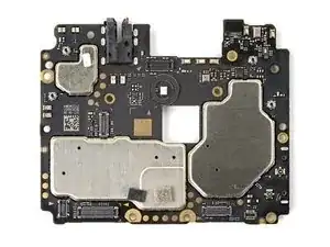
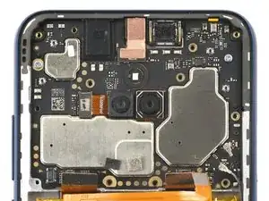
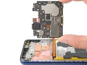
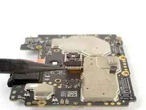
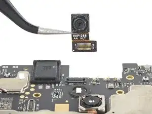
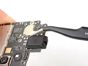
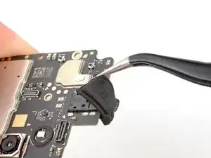
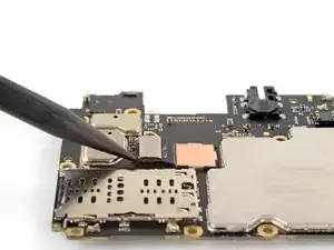
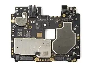
Follow this guide to replace the motherboard in your 2021 Motorola Moto G Play. This process involves removing the motherboard from the phone and stripping it of its accessory parts.
Werkzeuge
-
-
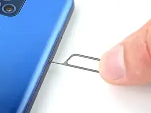
Insert a SIM card eject tool or a straightened paperclip into the hole adjacent to the SIM card tray.
-
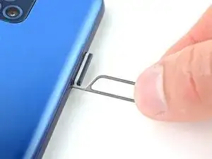
Press firmly to eject the tray.
-
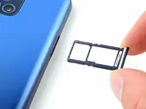
Grab and remove the SIM card tray from the phone.
-
-
-
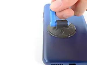
Apply a suction cup to the back cover, as close to the center of the left edge as possible.
-
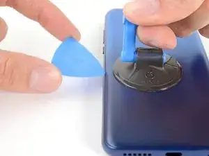
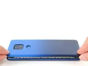
Pull up on the suction cup with strong, steady force to create a gap between the cover and the frame.
-
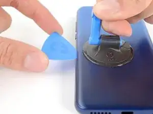
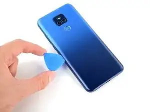
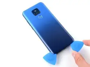
Insert an opening pick into the gap.
-
-
-
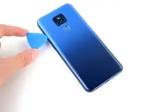
Slide your opening pick back and forth along the left edge to slice through the adhesive.
-
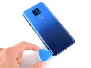
Leave the pick in at the bottom left corner to prevent the adhesive from resealing.
-
-
-
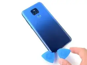
Insert and slide a second opening pick to the bottom right corner to slice through the adhesive.
-
Leave the pick inserted to prevent the bottom edge from resealing.
-
Repeat this process for the right and top edges of the cover.
-
-
-
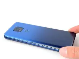
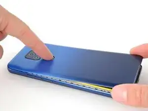
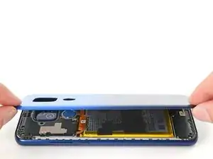
Grab and lift the bottom edge of the cover.
-
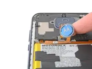
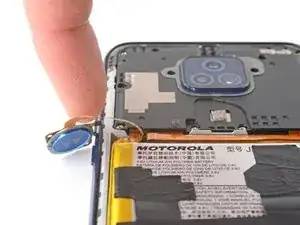
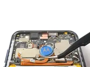
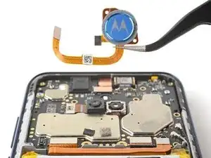
As you lift the back cover, press and unstick the fingerprint reader from it.
-
-
-
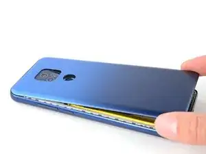
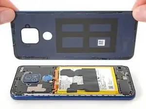
Grab and remove the back cover.
-
This is a good point to test your phone before sealing it up. Follow this guide to perform a hardware test. Be sure to power your phone back down completely before you continue working.
-
To adhere the back cover with custom-cut adhesives, follow this guide.
-
To adhere the back cover with tape, follow this guide.
-
-
-
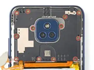
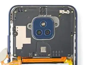
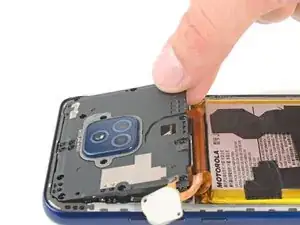
Use your Phillips screwdriver to remove the twelve 3.9 mm-long screws securing the motherboard cover.
-
-
-
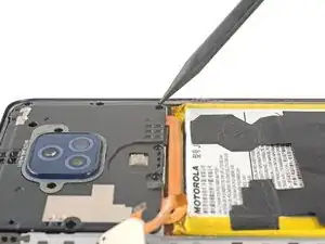
Insert the pointed end of a spudger between the bottom right corner of the motherboard cover and the frame.
-
Pry the cover upward until you can grab it with your fingers.
-
-
-
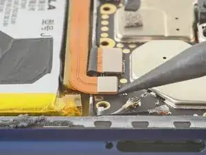
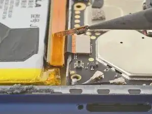
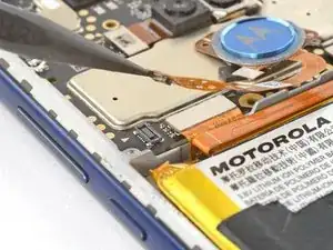
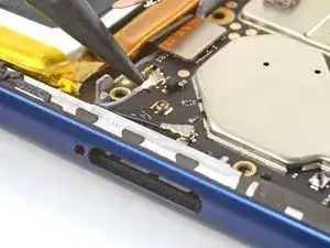
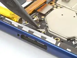
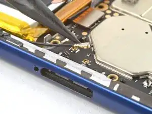
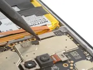
Use the pointed end of your spudger to pry and disconnect the fingerprint reader's press connector.
-
-
-
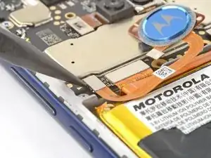
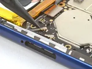
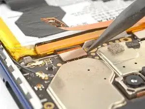
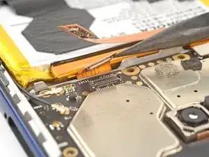
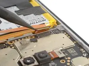
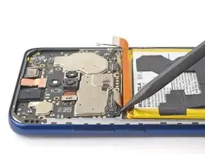
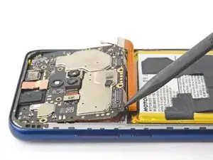
Use the pointed end of your spudger to pry and disconnect the board cable's press connector.
-
-
-
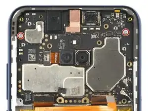
Use your Phillips screwdriver to remove the two 2.5 mm-long screws securing the motherboard.
-
-
-
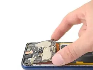
Insert the pointed end of your spudger between the bottom left edge of the motherboard and the frame.
-
Lift the motherboard from its recess.
-
-
-
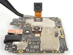
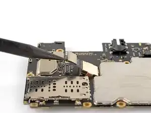
Use the pointed end of your spudger to pry and disconnect the depth camera's press connector.
-
Remove the camera.
-
-
-
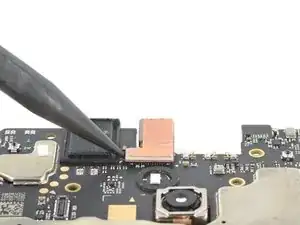
Use the pointed end of your spudger to pry and disconnect the front-facing camera's press connector.
-
Remove the camera.
-
-
-
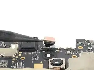
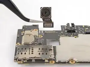
Use the pointed end of your spudger to pry and disconnect the main camera's press connector.
-
Remove the camera.
-
Compare your new replacement part to the original part—be sure to transfer remaining components and remove adhesive backings from the new part before installing.
To reassemble your device, follow these instructions in reverse order.
Take your e-waste to an R2 or e-Stewards certified recycler.
Repair didn’t go as planned? Try some basic troubleshooting, or ask our Answers community for help.
