Einleitung

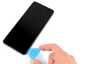
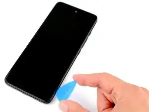
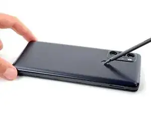
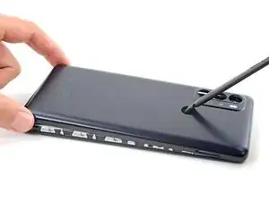
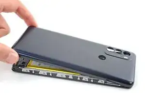
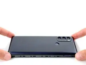
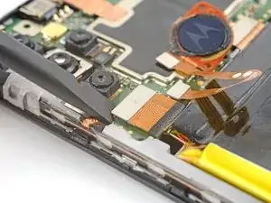
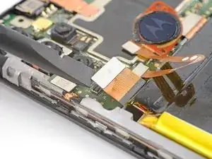
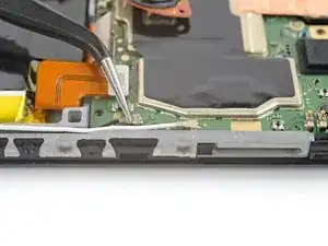
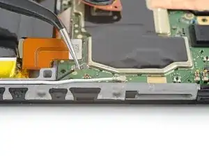
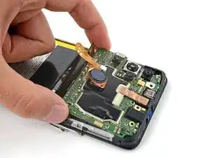
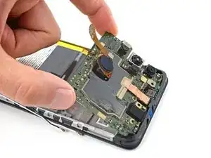
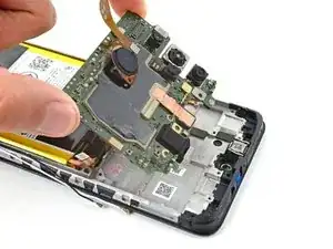
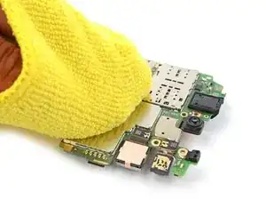
Use this guide to replace or remove the motherboard in your Motorola Moto G60S.

You'll need replacement adhesive to complete this repair.

  1. ITXueJJXMOItyDxc
    ITXueJJXMOItyDxc
    KxAKBtgMCuyPwYiF
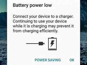
    • Before you begin, discharge your battery below 25%, as a charged lithium-ion battery can be dangerous if accidentally punctured.

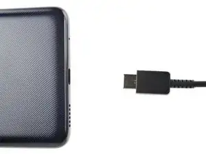
    • Power off your phone and unplug any cables.

  2. 6Sk4LQEGEu5f4Rrn
    6Sk4LQEGEu5f4Rrn
    qBuYkFovS1uJJpYw
    PfwSFxJWPEEd5mMi
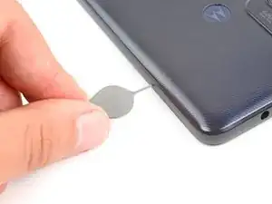
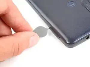
    • Insert a SIM eject tool, bit, or straightened paperclip into the SIM card tray hole on the left edge of the phone.

    • Push the SIM eject tool into the hole to eject the SIM card tray.

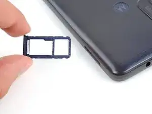
    • Remove the SIM card tray.

  3. 262BmGVtxuLcbaCS
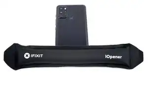
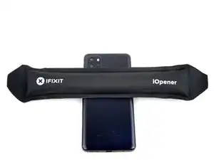
    • Heat an iOpener and apply it to the back cover's right edge for two minutes.

    • A hair dryer, heat gun, or hot plate may also be used, but be careful not to overheat the phone—the display and internal battery are both susceptible to heat damage.

  4. 2sZRMgfoVDABlOsM
    2sZRMgfoVDABlOsM
    WWypYXbRCWsT3b3e
    • Flip your phone over so the display is facing up.

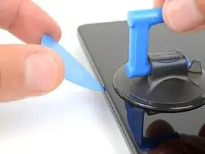
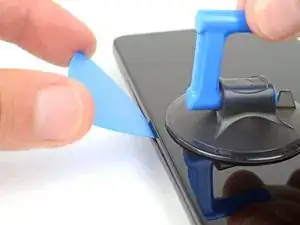
    • Apply a suction handle to the middle of the display's left edge, as close to the edge as possible.

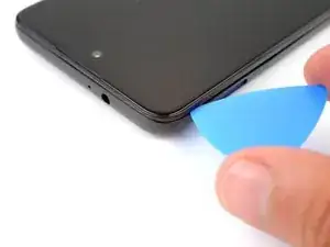
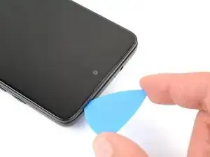
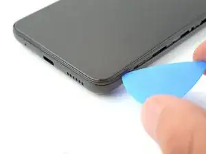
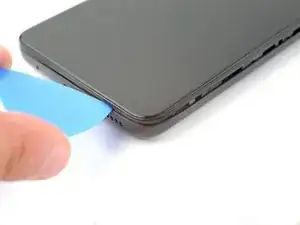
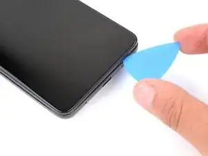
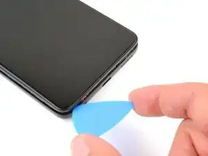
    • Place the tip of an opening pick in the small gap between the back cover and the display.

    • Pull up on the suction cup with a strong, steady force and push the opening pick down at a 45 degree angle until it slides into the gap between the back cover and the display.

    • If you're having a hard time inserting the pick, reheat the adhesive with an iOpener and try again.

  5. Jwq6X3oIW5CSMNde
    Jwq6X3oIW5CSMNde
    XVdw3WynUkFaKooT
    flZnrpDuQBkdNNdS
    • Both adhesive and clips secure the back cover.

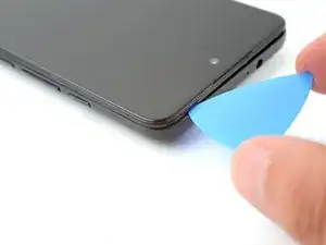
    • During steps that involve sliding the opening pick, keep it angled down at a 45 degree angle.

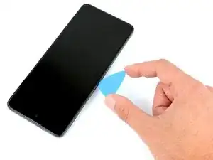
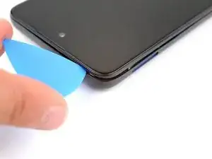
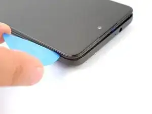
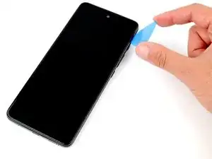
    • Slide the pick along the left edge down to the bottom left corner, and then up to the top left corner, to release the clips and slice the adhesive.

    • Leave the pick inserted in the top left corner to prevent the adhesive from resealing.

  6. En5NaWJohY2WfB5W
    • Flip your phone over and apply a heated iOpener to the back cover's top edge for two minutes.

  7. X3QGtCkKlZDj1GaB
    X3QGtCkKlZDj1GaB
    sjStBSNXuShLLlMH
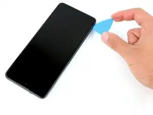
    • Flip your phone over and rotate the pick around the top left corner.

  8. EnSZwgjNqKnIMZ5q
    EnSZwgjNqKnIMZ5q
    JjZ6PWiSn6rSgPSV
    • Slide the pick along the top edge to release the clips and slice the adhesive.

    • Leave the pick inserted in the top right corner.

  9. nEx3NuPLeOE2DCYG
    • Flip your phone over and apply a heated iOpener to the back cover's left edge for two minutes.

  10. vMAnVRlh2ALqc1d3
    vMAnVRlh2ALqc1d3
    juhXylUWG1TWatQW
    • Flip your phone over and rotate the pick around the top right corner.

  11. C5NnLPYUTn236dYL
    C5NnLPYUTn236dYL
    bFQHgSYXYxiKsHKT
    • Slide the pick along the right edge to release the clips and slice the adhesive.

    • Leave the pick inserted in the bottom right corner to prevent the adhesive from resealing.

  12. dPBjLmCbVcr1FlPF
    • Flip your phone over and apply a heated iOpener to the back cover's bottom edge for two minutes.

  13. hgAkTJouSGpSHKVI
    hgAkTJouSGpSHKVI
    ZINh4gZfEjUqD56e
    • Flip your phone over and rotate the pick around the bottom right corner.

  14. KKbkmlWRNfGZKT5X
    KKbkmlWRNfGZKT5X
    dFj5aOH4AMZdNc1q
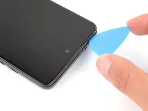
    • Slide the opening pick along the bottom edge to release the clips and slice the adhesive.

  15. AqP16lCixg6cjLHx
    AqP16lCixg6cjLHx
    jNyZFZQkJgo41qQZ
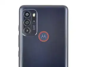
    • Flip your phone over and apply a heated iOpener to the fingerprint sensor on the back cover for two minutes.

  16. cyiKEFRXheDpqIW1
    cyiKEFRXheDpqIW1
    6RbWUhAvnSsvW1YN
    nLiWjh4Jhlc4FEIC
    • Adhesive secures the fingerprint sensor to the back case.

    • A fragile cable secures the fingerprint sensor to the motherboard. Be very careful during this step to avoid damaging the cable.

    • Press down on the fingerprint sensor with the flat end of a spudger or your finger.

    • While pressing down on the fingerprint sensor, gently pull up the bottom edge of the back cover until the sensor detaches.

  17. SZChLCoCquXQRHNN
    SZChLCoCquXQRHNN
    fHiGDRKPUHGdT4Sf
    MDyxLvKijNlFxUGj
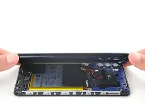
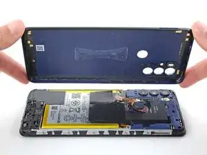
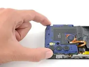
    • Lift the back cover up and remove it.

    • If the back cover is still stuck to the frame, slide an opening pick around the entire perimeter until the cover separates completely.

    • During reassembly:

    • This is a good point to test your phone's functionality before sealing it up. Use this guide to run a hardware test. Be sure to power your phone back down completely before you continue working.

    • Apply new adhesive to the perimeter of the underside of the back cover after cleaning the relevant areas with isopropyl alcohol (>90%) and a micro-fiber cloth.

  18. wBcemIDbMgWtxbmU
    wBcemIDbMgWtxbmU
    KHFYuEZENwnMaxXY
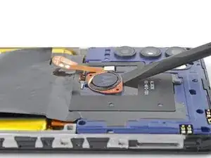
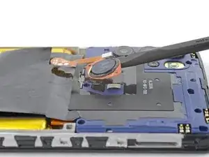
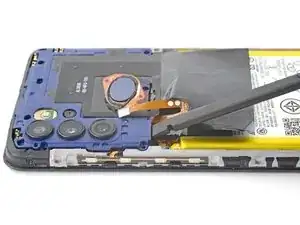
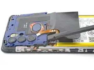
    • The fingerprint reader is secured to the motherboard cover with light adhesive.

    • Insert the flat end of a spudger under the fingerprint sensor.

    • Gently pry up and detach the fingerprint sensor from the motherboard cover.

    • Don't try to remove the fingerprint sensor yet, as it's still attached to the motherboard by a delicate ribbon cable.

  19. SDR3AQlFyJcr3GSx
    SDR3AQlFyJcr3GSx
    yPMLRtSfSiny31hQ
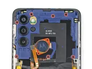
    • Use a Phillips screwdriver to remove the seven 3.9 mm screws securing the motherboard cover.

  20. nWW2py4TvQHoFfyY
    nWW2py4TvQHoFfyY
    lQjpfm22bl2iW5lG
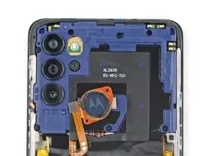
    • The motherboard cover is secured with tight clips.

    • Insert the flat end of a spudger in the gap between the frame and the bottom left corner of the motherboard cover.

    • Lift straight up with the spudger to release the clips securing the motherboard.

    • Don't pry against the battery, as this could damage it.

    • This may take take a few attempts. It you're having trouble, try gripping the spudger closer to the flat end.

    • During reassembly, press down around the perimeter of the motherboard cover to engage the clips.

  21. m1BkC4Ud1NiMAcul
    m1BkC4Ud1NiMAcul
    tNtfKmEEFIYBTpIp
    • Pull the motherboard cover towards the top of the phone to remove it.

    • Make sure to avoid the fingerprint sensor cable when removing the cover, as it can easily rip.

  22. Ts2wpwJZQjsUkngJ
    Ts2wpwJZQjsUkngJ
    cjVBvgH2DXqEtNET
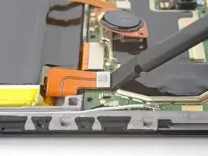
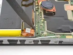
    • Use the flat end of a spudger to pry up and disconnect the battery cable's press connector.

    • To re-attach press connectors like this one, carefully align and press down on one side until it clicks into place, then repeat on the other side. Don't press down on the middle. If the connector is misaligned, the pins can bend and cause permanent damage.

  23. n6TNPq6MNgE1lFmV
    n6TNPq6MNgE1lFmV
    r2AJ1sggwXi6sLEE
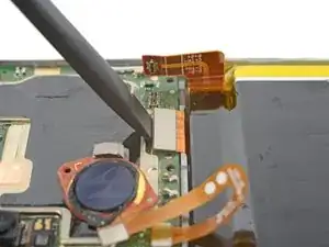
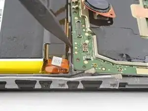
    • Use the flat end of a spudger to pry up and disconnect the interconnect cable's press connector from the motherboard.

  24. EeYZnCuFjiSWLx5B
    EeYZnCuFjiSWLx5B
    VnfJUp35MCRU5ENx
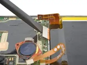
    • Use the flat end of a spudger to lift up and disconnect the display cable's press connector.

    • Pry on the corner of the press connector closest to the left edge of the phone to avoid damaging the depth camera.

  25. dBPEoFoZ55TEetnQ
    dBPEoFoZ55TEetnQ
    MMdYWRXDqEMgAbGF
    MkZGrljJiDeALIpy
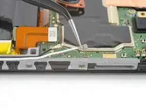
    • Use angled tweezers to grip the antenna's black coaxial connector, as close to the connector head as possible.

    • Gently lift straight up to disconnect the cable.

    • Be gentle when disconnecting the cable, as it's very easy to tear the socket from the motherboard.

    • Repeat the disconnection procedure on the white antenna cable.

    • To reattach coaxial connectors like these, align the connector over its socket and press down with the flat end of a spudger. The connector should snap into place. This can be tricky and may take a few tries.

    • During reassembly, make sure the antenna cables are in their groove on the edge of the phone.

  26. DGnCJwvZAoeZuVbS
    DGnCJwvZAoeZuVbS
    EQWRFqhdWs4PDJNg
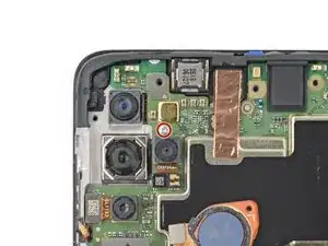
    • Use a Phillips screwdriver to remove the 3 mm screw securing the motherboard.

  27. iRVZvDVsbbmv1DmQ
    iRVZvDVsbbmv1DmQ
    kF2HxFUwgJxn1PQG
    • Insert the pointed end of a spudger in the gap between the frame and the bottom right corner of the motherboard.

    • Gently lift the motherboard up until you are able to grab its edges with your fingers.

    • Don't pry against the battery, as this could damage it.

  28. HrkYOuIMjTkOsTgW
    HrkYOuIMjTkOsTgW
    dyb1IkAFFWnCEagq
    CAZ6kjIoxwdcTKmT
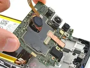
    • Lift the bottom edge of the motherboard up and pull towards the bottom of the phone to remove it.

    • You may feel a bit of resistance. This is normal, since the midframe is slightly bonded to the heat sink with thermal paste.

    • During reassembly:

    • Move all cables that connect to the motherboard (battery, display, interconnect, and antennas) out of the way so they don't get stuck under the motherboard when it's reinserted.

    • Reinsert the motherboard at a downward angle to position the headphone jack and proximity sensor back into their recesses.

  29. DDVqePRjO4JP2NjR
    DDVqePRjO4JP2NjR
    BhuYsY2MIwLOTMXY
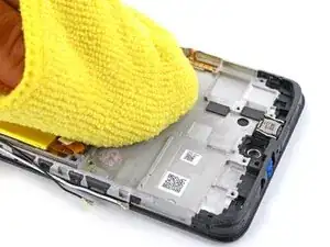
    • Clean off the old thermal paste from the midframe and motherboard using isopropyl alcohol and a microfiber cloth. Apply new thermal paste before reassembly.

  30. EunHT2ikJhOIB5sN
    EunHT2ikJhOIB5sN
    FoRQeNDw3S4Som3D
    m6FykDSeZGGtGtWR
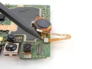
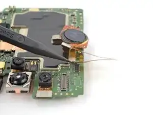
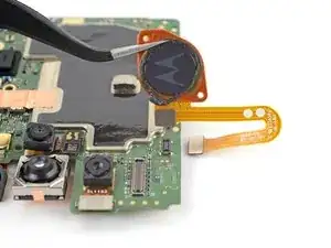
    • Use the pointed end of a spudger to pry up and disconnect the fingerprint sensor's press connector.

    • There's no adhesive securing the fingerprint sensor to the motherboard. Be careful disconnecting the press connector, as it may eject the fingerprint sensor.

    • Use tweezers or your fingers to remove the fingerprint sensor.

  31. erloHyRm2tqaSSHw
    erloHyRm2tqaSSHw
    pfH3iDhHOgYOYOPn
    McXrvTatxBxpAnJ3
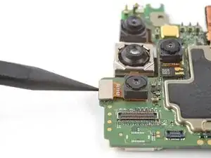
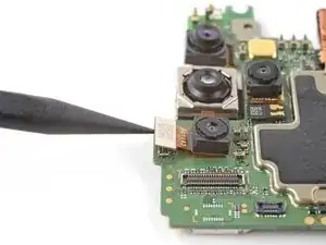
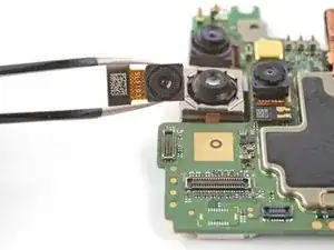
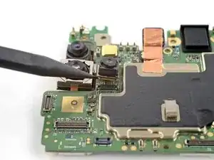
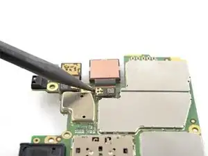
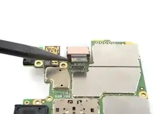
    • Use the pointed end of a spudger to pry up and disconnect the depth camera's press connector.

    • There's no adhesive securing the camera to the motherboard. Be careful disconnecting the press connector, as it may eject the camera.

    • Use tweezers or your fingers to remove the camera.

  32. orJj3TIw2fOqhv1L
    orJj3TIw2fOqhv1L
    PPiRNouRXGs2QpRC
    gnSP6HHCnTaxILjn
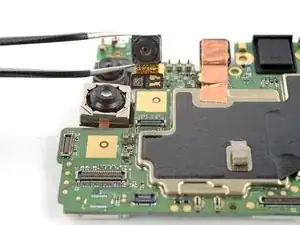
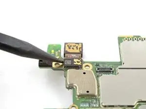
    • Use the pointed end of a spudger to pry up and disconnect the macro camera's press connector.

    • There's no adhesive securing the camera to the motherboard. Be careful disconnecting the press connector, as it may eject the camera.

    • Use tweezers or your fingers to remove the camera.

  33. Bq2EDlN5XTsCngq6
    Bq2EDlN5XTsCngq6
    TrYgB3SZcmS3N2iL
    1IPP6L6dXTUoIH1k
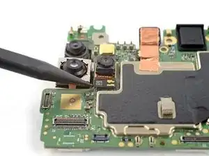
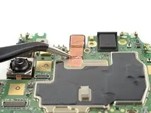
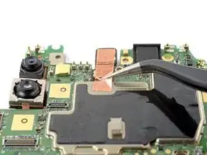
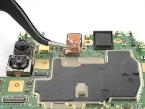
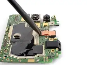
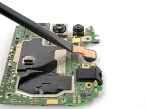
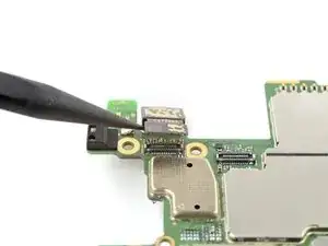
    • Use tweezers to grip the copper tape on the front camera, just below the press connector.

    • Very slowly peel the tape up.

    • Be very careful when peeling the tape, as it's extremely delicate.

    • Repeat the process on the other side of the tape.

  34. byXxnAQERRXFOprO
    byXxnAQERRXFOprO
    crSNONGnOr12sJIH
    qXYosrRkeKQTJFRE
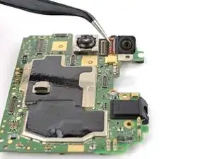
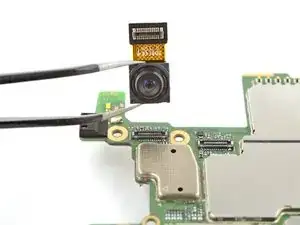
    • Use the flat end of a spudger to pry up and disconnect the front facing camera's press connector.

    • There's no adhesive securing the camera to the motherboard. Be careful disconnecting the press connector, as it may eject the camera.

    • Use tweezers or your fingers to remove the camera.

  35. X6TIRY1LEDTTYSEa
    X6TIRY1LEDTTYSEa
    qc1DNGjSvJs2mYIR
    6X5Oo2IuemkqGsIk
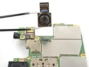
    • Flip the motherboard over to access the main and ultra-wide cameras.

    • Be very careful not to bend the spring contacts when the motherboard is flipped over. Consider putting something under the motherboard to protect the contacts, such as a microfiber cloth.

    • Use the pointed end of a spudger to pry up and disconnect the main camera's press connector.

    • There's no adhesive securing the camera to the motherboard. Be careful disconnecting the press connector, as it may eject the camera.

    • Use tweezers or your fingers to remove the camera.

  36. TklBOTCuRZDAZHpx
    TklBOTCuRZDAZHpx
    BKhP1jwuIo1KYvOM
    pQbbp4R3AhBCeMYE
    • Use the pointed end of a spudger to pry up and disconnect the ultra-wide camera's press connector.

    • There's no adhesive securing the camera to the motherboard. Be careful disconnecting the press connector, as it may eject the camera.

    • Use tweezers or your fingers to remove the camera.

  37. Ib2JJBTXHDGeGixy
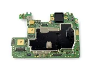
    • You're left with the motherboard.

    • Compare your new replacement part to the original part—you may need to transfer remaining components from the new part before you install it.

Abschluss

To reassemble your device, follow the instructions in reverse order.

Take your e-waste to an R2 or e-Stewards certified recycler.

Repair didn’t go as planned? Try some basic troubleshooting, or ask our Answers community for help.
Spencer Day

Mitglied seit: 14/09/22

17445 Reputation

0 Kommentare