Einleitung
Folge dieser Anleitung, um ein defektes/beschädigtes LCD einer Nintendo Switch Lite auszutauschen.
In der Switch Lite sind JIS-Schrauben verbaut, zur Not passen aber auch Bits für Kreuzschlitzschrauben. Sei aber sehr vorsichtig und beschädige die Schraubenköpfe nicht. Die Bits von iFixit können auch für JIS-Schrauben verwendet werden.
Hinweis: Der Ausbau der Joysticks oder Tasten ist nicht notwendig, aber dies macht diese Reparatur um ein Vielfaches einfacher.
Hinweis: Diese Anleitung gilt nur für das LCD alleine. Wenn du die Displayeinheit, also Display mit daran befestigtem Touchscreen austauschen willst, dann verwende [lguide|156978|diese Anleitung|new_window=true]. Falls das Display gerissen oder zersprungen ist, aber noch funktioniert, folge stattdessen der Anleitung zum Austausch des Touchscreens.
Hinweis: Für diese Reparatur ist es notwendig sowohl das Abschirmblech als auch den Kühlkörper zu entfernen. Die alte Wärmeleitpaste muss von diesen Bauteilen sowie der CPU sauber entfernt werden und neu aufgetragen werden, bevor das Abschirmblech und der Kühlkörper wieder eingebaut werden.
-
-
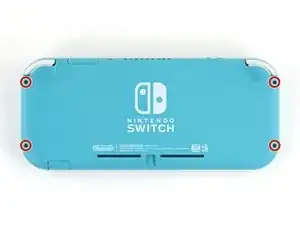
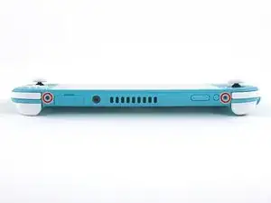
Nimm einen JIS 000 Schraubendreher/Bit oder ein Original PH000 Bit von iFixit und entferne folgende JIS-Schrauben, mit denen die Rückseite oben und unten befestigt ist:
-
Zwei 3,6 mm lange Kreuzschlitzschrauben an der Oberkante des Gerätes
-
Zwei 3,6 mm lange Kreuzschlitzschrauben an der Unterkante des Gerätes
-
Passe auf, dass die Schraubenköpfe nicht rundgedreht werden. Drücke das Werkzeug fest nach unten und arbeite langsam. Wenn die Schrauben nicht herauskommt, dann versuchen es mit einem anderen Bit.
-
-
-
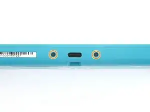
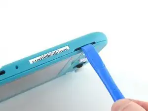
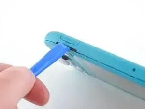
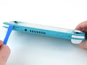
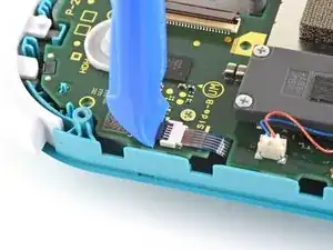
Setze ein Öffnungswerkzeug in die linke Öffnung für den Lautsprecher an der Unterseite des Geräts ein.
-
Verdrehe das Werkzeug, so dass sich die Rasten lösen, mit denen die Rückseite befestigt ist.
-
-
-
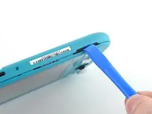
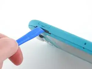
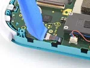
Schiebe das Öffnungswerkzeug um die untere linke Ecke herum, so dass sich die Rasten auf der linken Seite des Geräts lösen.
-
-
-
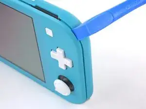
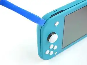
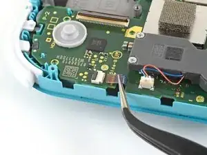
Setze ein Öffnungswerkzeug in die rechte Öffnung für den Lautsprecher an der Unterseite des Geräts ein.
-
Verdrehe das Werkzeug, so dass sich die Rasten lösen, mit denen die Rückseite befestigt ist.
-
-
-
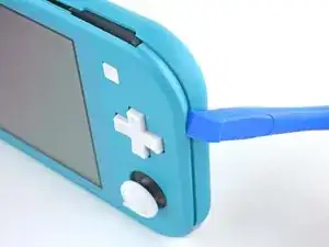
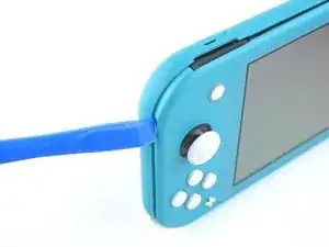
Schiebe das Öffnungswerkzeug um die untere rechte Ecke herum, so dass sich die Rasten auf der rechten Seite des Geräts lösen.
-
-
-
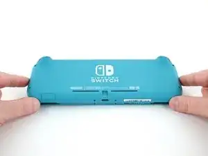
Schiebe das Werkzeug weiter am Spalt an der Oberseite des Geräts entlang und heble die Rasten auf.
-
-
-
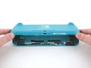
Hebe die Unterkante der Rückseite an und klappe sie wie ein Buch auf.
-
Entferne die Rückseite.
-
-
-
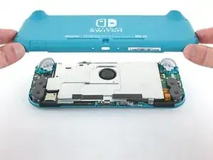
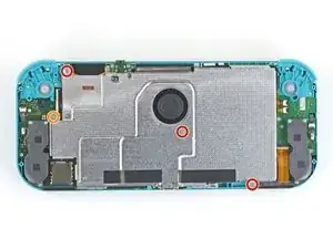
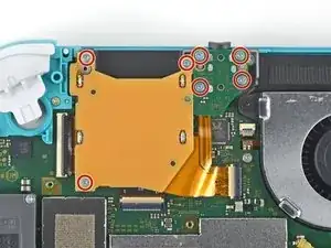
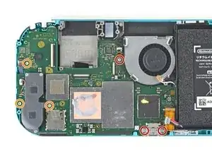
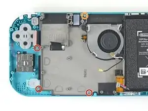
Nimm einen JIS 000 Schraubendreher/Bit oder ein Original PH000 Bit von iFixit und entferne folgende vier JIS-Schrauben:
-
drei 3,1 mm Schrauben
-
eine 4,5 mm Schraube
-
-
-
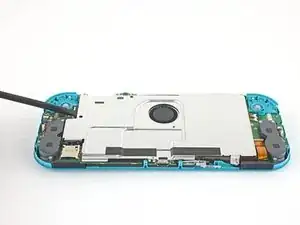
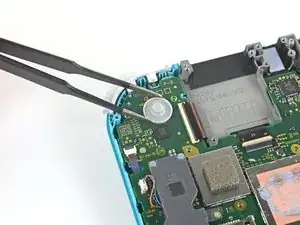
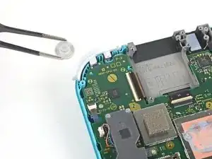
Hebe mit dem Finger oder einem Spudger das Abschirmblech hoch und entferne es aus dem Gerät.
-
Entferne das Abschirmblech.
-
-
-
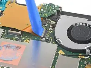
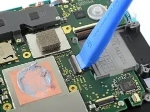
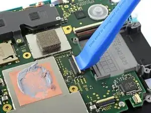
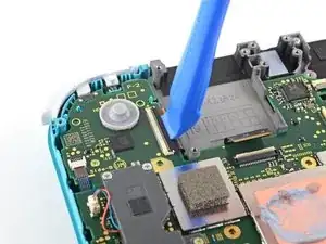
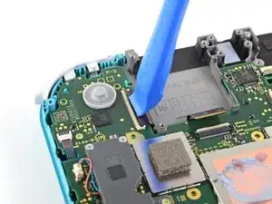
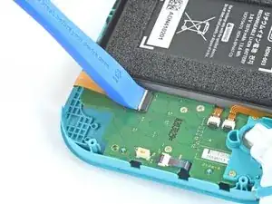
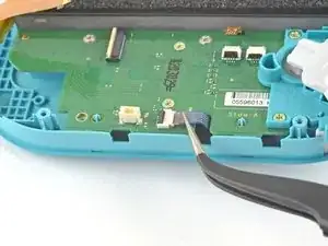
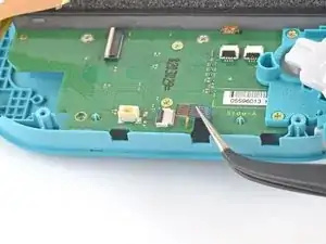
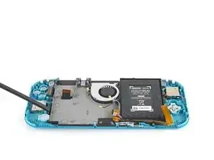
Klappe den kleinen, scharnierartigen Sicherungsbügel am ZIF-Verbinder des Verbindungskabels auf der Hauptplatine mit dem Fingernagel oder einem Öffnungswerkzeug hoch.
-
-
-
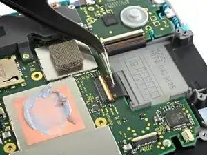
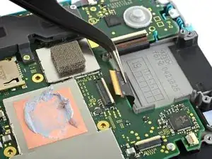
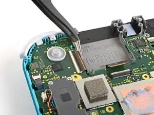
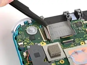
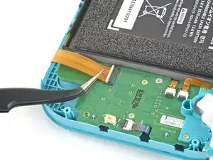
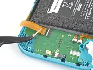
Schiebe das Verbindungskabel mit Hilfe einer Pinzette aus dem Anschluss auf der Hauptplatine heraus.
-
-
-
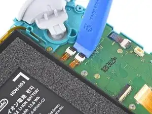
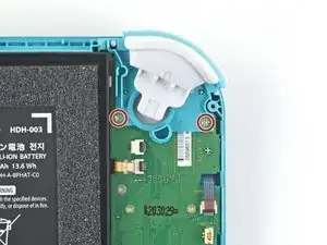
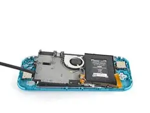
Heble den Akkuanschluss mit der Spudgerspitze gerade nach oben aus seinem Anschluss auf der Hauptplatine heraus.
-
-
-
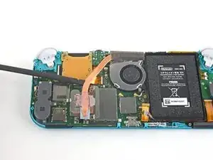
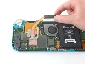
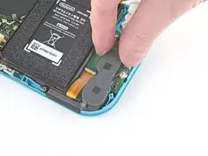
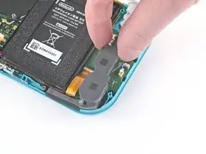
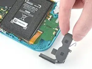
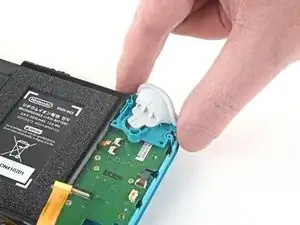
Entferne den leicht verklebten Schaumstoff am Lüfter mit dem flachen Ende eines Spudgers oder mit deinem Finger.
-
-
-
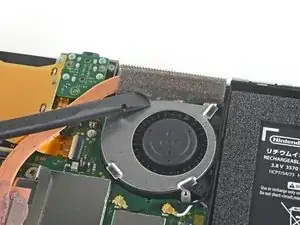
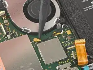
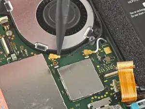
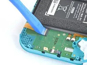
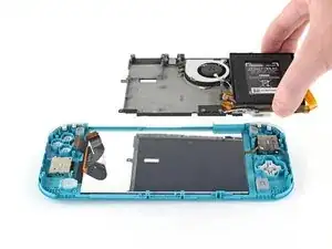
Nimm einen JIS 000 Schraubendreher/Bit oder ein Original PH000 Bit von iFixit und entferne die drei 3 mm JIS Schrauben, mit denen der Kühlkörper an der Hauptplatine befestigt ist.
-
-
-
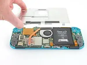
Hebe den Kühlkörper mit dem Finger oder einem Spudger von der Hauptplatine hoch und entferne ihn.
-
-
-
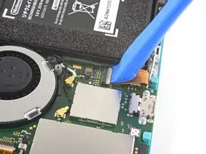
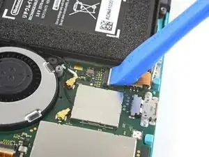
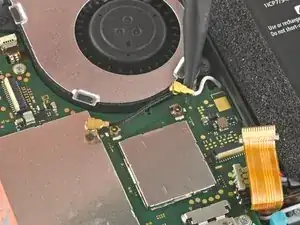
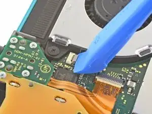
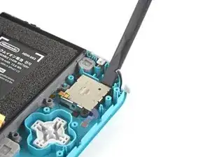
Klappe den kleinen, scharnierartigen Sicherungsbügel am ZIF-Verbinder des Kabels zum Game Card Leser mit dem Fingernagel oder einem Öffnungswerkzeug hoch.
-
-
-
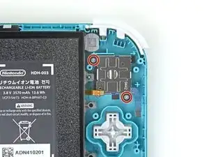
Nimm einen JIS 000 Schraubendreher/Bit oder ein Original PH000 Bit von iFixit und entferne die sieben 3,1 mm JIS-Schrauben, mit denen der Game Card Leser und die Kopfhörerbuchse befestigt sind.
-
-
-
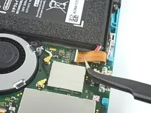
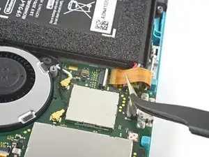
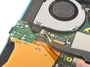
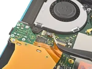
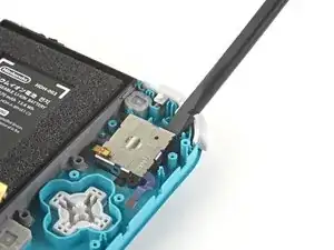
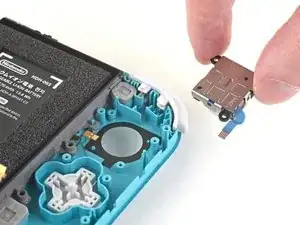
Bewege den Game Card Leser mit einer Pinzette oder deinen Fingern nach links, so dass das Kabel aus seinem Anschluss herausgleitet.
-
Entferne den Game Card Leser und die Kopfhörerbuchse.
-
-
-
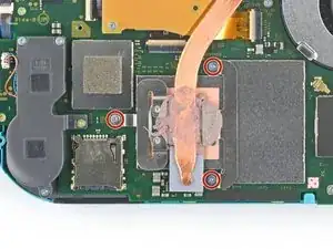
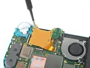
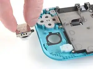
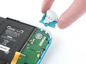
Nimm einen JIS 000 Schraubendreher/Bit oder ein Original PH000 Bit von iFixit und entferne die beiden 4,5 mm JIS-Schrauben, mit denen die Baugruppe der rechten Trigger-Taste an der Hauptplatine befestigt ist.
-
-
-
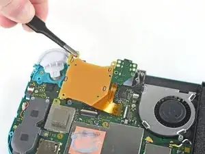
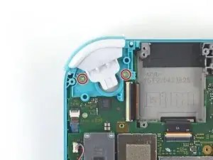
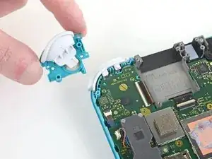
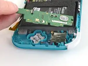
Wenn das Gummipad nicht an der rechten Trigger-Taste hängen geblieben ist, dann hole es jetzt mit einer Pinzette oder den Fingern heraus.
-
-
-
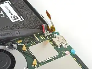
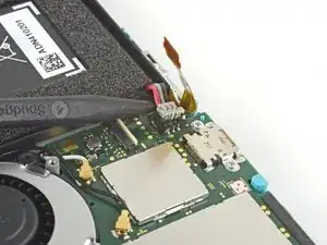
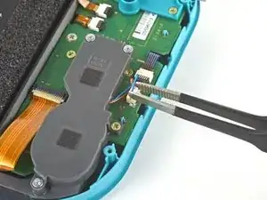
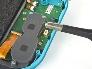
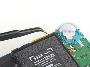
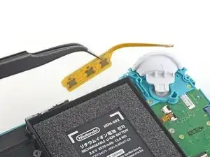
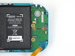
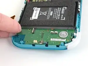
Heble das schwarze Antennenkabel mit der Spudgerspitze gerade nach oben aus dem Anschluss auf der Hauptplatine hoch.
-
Wiederhole das Ganze für das weiße Antennenkabel.
-
-
-
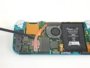
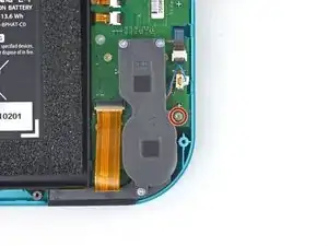
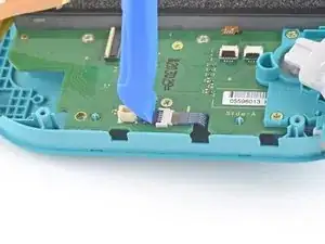
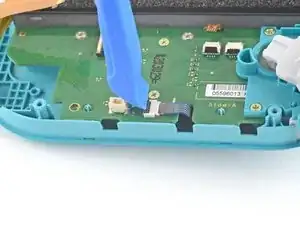
Klappe den kleinen, scharnierartigen Sicherungsbügel am ZIF-Verbinder des Lüfterkabels mit einem Öffnungswerkzeug oder dem Fingernagel auf.
-
-
-
Schiebe das Lüfterkabel mit einer Pinzette aus seinem Anschluss auf der Hauptplatine heraus.
-
-
-
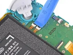
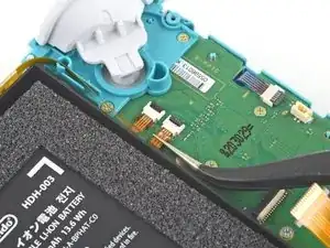
Klappe den kleinen, scharnierartigen Sicherungsbügel am ZIF-Verbinder des Displaykabels mit einem Öffnungswerkzeug oder dem Fingernagel auf.
-
-
-
Schiebe das Displaykabel mit einer Pinzette aus seinem Anschluss auf der Hauptplatine heraus.
-
-
-
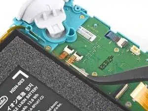
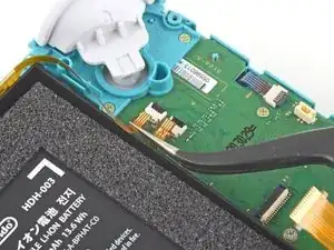
Klappe den kleinen, scharnierartigen Sicherungsbügel am ZIF-Verbinder des Touchscreenkabels mit einem Öffnungswerkzeug oder dem Fingernagel auf.
-
-
-
Schiebe das Touchscreenkabel mit einer Pinzette aus seinem Anschluss auf der Hauptplatine heraus.
-
-
-
Klappe den kleinen, scharnierartigen Sicherungsbügel am ZIF-Verbinder des Kabels zum rechten Joystick mit einem Öffnungswerkzeug oder dem Fingernagel auf.
-
-
-
Schiebe das Kabel zum rechten Joystick mit einer Pinzette aus seinem Anschluss auf der Hauptplatine heraus.
-
-
-
Nimm einen JIS 000 Schraubendreher/Bit oder ein Original PH000 Bit von iFixit und entferne folgende sechs JIS-Schrauben, mit denen die Hauptplatine befestigt ist:
-
Drei 3,1 mm Schrauben
-
Drei 4,5 mm Schrauben
-
-
-
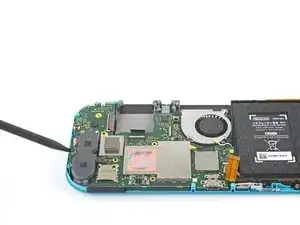
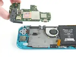
Setze einen Spudger in den Spalt zwischen den Rahmen und der Hauptplatine ein. Hebe dann die Hauptplatine aus ihrer Vertiefung heraus.
-
Entferne die Hauptplatinen-Baugruppe.
-
-
-
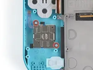
Nimm einen JIS 000 Schraubendreher/Bit oder ein Original PH000 Bit von iFixit und entferne die beiden 3,5 mm JIS-Schrauben, mit denen der rechte Joystick befestigt ist.
-
-
-
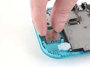
Ziehe den Kabelstecker zum linken Lautsprecher mit einer Pinzette oder deinen Fingern gerade nach oben und löse ihn aus seinem Anschluss auf der Hauptplatine.
-
-
-
Nimm einen JIS 000 Schraubendreher/Bit oder ein Original PH000 Bit von iFixit und entferne die 4,5 mm JIS-Schraube, die das linke Lautsprechermodul befestigt.
-
-
-
Klappe den kleinen, scharnierartigen Sicherungsbügel am ZIF-Verbinder des Verbindungskabels zur Hauptplatine mit einem Öffnungswerkzeug oder dem Fingernagel auf.
-
-
-
Schiebe das Verbindungsabel der Hauptplatine mit einer Pinzette aus seinem Anschluss auf der Tochterplatine heraus.
-
-
-
Klappe die kleinen, scharnierartigen Sicherungsbügel an den ZIF-Verbindern der beiden Kabel mit einem Öffnungswerkzeug oder dem Fingernagel auf.
-
-
-
Schiebe das Displaykabel der Tochterplatine mit einer Pinzette aus seinem Anschluss auf der Hauptplatine heraus.
-
Wiederhole das Ganze für das Flachbandkabel zu den Lautstärketasten.
-
-
-
Klappe den kleinen, scharnierartigen Sicherungsbügel am ZIF-Verbinder des Kabels zum linken Joystick mit einem Öffnungswerkzeug oder dem Fingernagel auf.
-
-
-
Schiebe das Kabel zum linken Joystick mit einer Pinzette aus seinem Anschluss auf der Tochterplatine heraus.
-
-
-
Nimm einen JIS 000 Schraubendreher/Bit oder ein Original PH000 Bit von iFixit und entferne die beiden 4,5 mm JIS-Schrauben, mit denen die Baugruppe der linken Trigger-Taste befestigt ist.
-
-
-
Nimm einen JIS 000 Schraubendreher/Bit oder ein Original PH000 Bit von iFixit und entferne die folgenden vier JIS-Schrauben:
-
Zwei 4,5 mm JIS-Schrauben
-
Zwei 6 mm JIS-Schrauben
-
-
-
Nimm einen JIS 000 Schraubendreher/Bit oder ein Original PH000 Bit von iFixit und entferne die beiden 3,5 mm JIS-Schrauben, mit denen der linke Joystick befestigt ist.
-
-
-
Hebe den Joystick mit dem flachen Ende des Spudgers nach oben aus seiner Vertiefung heraus.
-
Entferne den Joystick mit der Hand.
-
-
-
Nimm einen JIS 000 Schraubendreher/Bit oder ein Original PH000 Bit von iFixit, um die folgenden vier Schrauben zu entfernen:
-
Drei 2,5 mm Schrauben
-
Eine 6 mm Schraube
-
-
-
Benutze einen Spudger oder deine Finger, um die Mittelrahmen-Baugruppe aus ihrer Vertiefung zu heben.
-
Entferne die Mittelrahmen-Baugruppe.
-
-
-
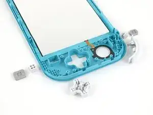
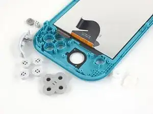
Jetzt ist es an der Zeit alle Tasten zu entfernen (sofern noch nicht geschehen), um zu verhindern, dass du welche verlierst.
-
-
-
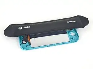
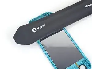
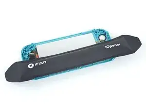
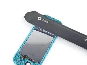
Erwärme einen iOpener und lege ihn 1-2 Minuten auf die obere Kante des LCDs, um den Kleber aufzuweichen.
-
-
-
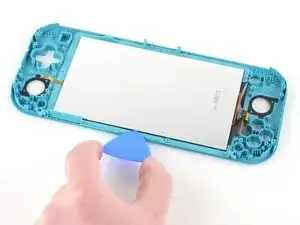
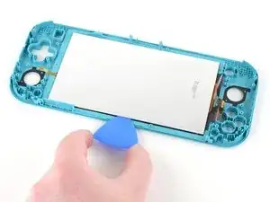
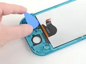
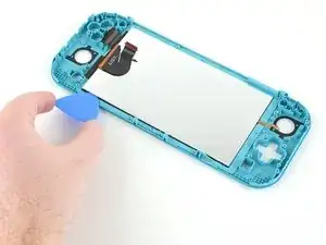
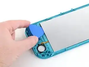
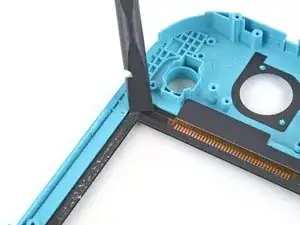
Setze ein Plektrum zwischen den Rahmen und die Oberkante des LCD ein, um die beiden Komponenten voneinander zu lösen.
-
-
-
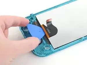
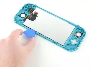
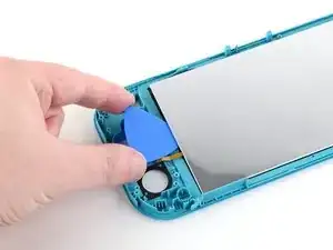
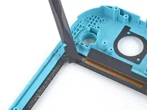
Schiebe das Plektrum nun entlang der oberen Kante des LCDs, um den Kleber zu durchtrennen.
-
-
-
Lege nun zwei Minuten lang den erwärmten iOpener auf die rechte Kante an der Rückseite des LCDs, um den Kleber aufzuweichen.
-
-
-
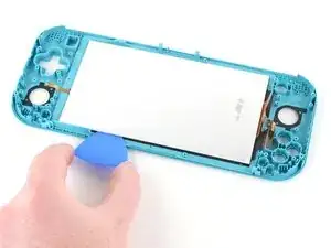
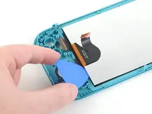
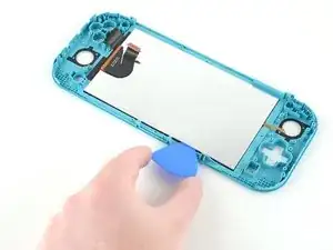
Schiebe das Plektrum weiter an der rechten Kante des LCDs entlang, um den Kleber aufzutrennen.
-
-
-
Führe das Plektrum weiter an der Unterkante des LCDs entlang, um den Kleber aufzutrennen.
-
-
-
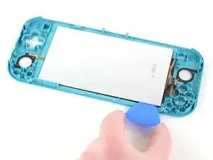
Schiebe das Plektrum weiter an der linken Kante des LCDs entlang, um den Kleber aufzutrennen.
-
-
-
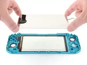
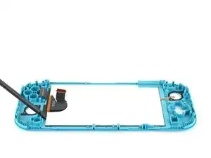
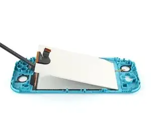
Benutze nun die flache Seite deines Spudgers oder deine Finger, um das LCD nach oben aus dem Rahmen heraus zu heben.
-
-
-
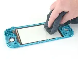
Benutze das flache Ende eines Spudgers, um die Klebereste rund um den Touchscreen herum zu entfernen.
-


Um dein Gerät wieder zusammenzubauen, folge den Schritten dieser Anleitung in umgekehrter Reihenfolge.
Entsorge deinen Elektromüll fachgerecht.
Lief die Reparatur nicht wie geplant? Versuche es mit einigen grundsätzlichen Lösungsansätzen oder frage in unserem Nintendo Switch Lite Forum nach.

12 Kommentare
Followed the guide to replaced a cracked screen on a Switch Lite, all good, guide was easy to follow and refitting wasn't too hard either, just a reversal of the disassembly
Fantastic guide, exactly what I was looking for! Unfortunately I managed to make the tape unusable and I need tape to connect the lcd to the digitizer and the digitizer to the case. I will likely use 2-3mm tape for the lcd to digitizer but I'm unsure what to use to connect the digitizer to the case. Any suggestions?
Sam Red -
Thanks for taking the time to type this up. Really appreciate the effort that went in to this guide.
All my screws got stripped any ideas on how to remove?
Almost A Mammal -
A Y0 screwdriver seemed to work better for me.
Tommy Morrill -
What type of screw driver do I use to un screw the screws and which way
Luca Capito -