Einleitung
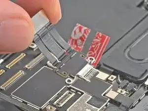
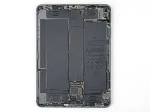
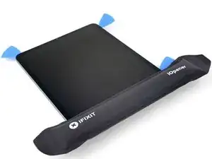
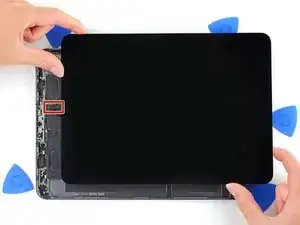
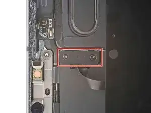
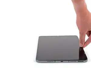
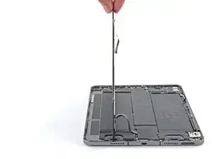
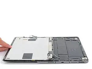
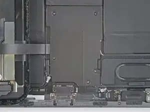
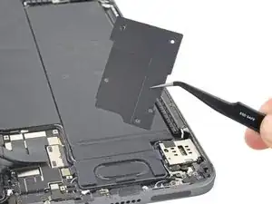
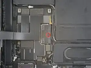
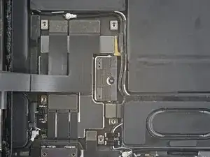
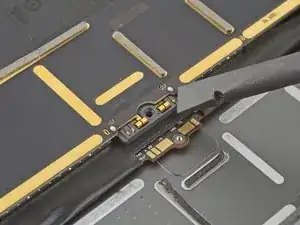
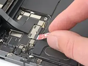
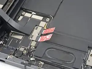
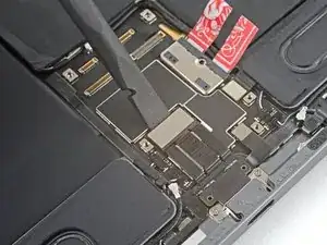
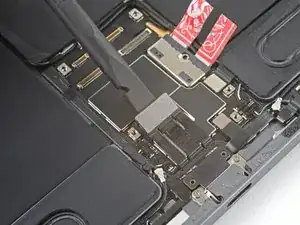
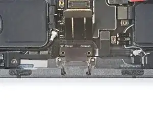
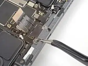
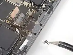
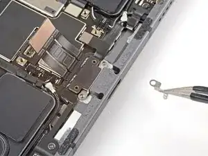
Follow this guide to replace the USB-C port on your iPad Pro 11" 3rd-gen.
This guide is written with an A2301 (cellular + mmWave) model iPad Pro. If you're fixing a Wi-Fi model, you can still use this guide—there will be some visual discrepancies, and you'll need to skip the steps related to the cellular antennas.
Some photos in this guide show the screen disconnected and fully removed. This isn't necessary for the procedure, so this guide skips those steps. If you wish to remove the screen, follow this guide.
Werkzeuge
-
-
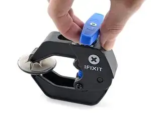
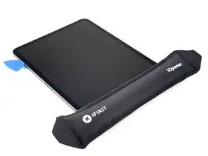
Pull the blue handle towards the hinge to disengage opening mode.
-
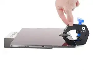
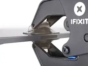
Elevate the iPad enough for the Anti-Clamp's arms to rest above and below the screen.
-
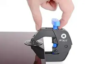
Position the suction cups near the right edge of the iPad—one on the front, and one on the back.
-
Push down on the cups to apply suction to the desired area.
-
-
-
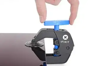
Push the blue handle away from the hinge to engage opening mode.
-
Turn the handle clockwise until you see the cups start to stretch.
-
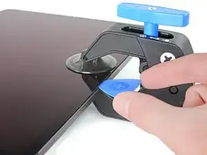
Wait one minute to give the adhesive a chance to release and present an opening gap.
-
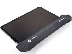
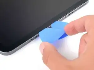
Insert an opening pick under the screen when the Anti-Clamp creates a large enough gap.
-
Skip the next step.
-
-
-
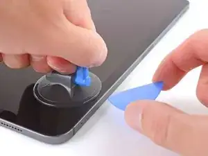
Apply a suction handle to the right edge of the screen, about 5 cm from the bottom edge.
-
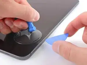
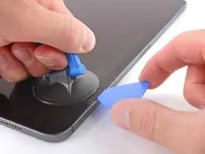
Pull up on the suction handle with firm, constant pressure to create a gap just small enough to insert an opening pick.
-
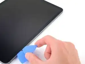
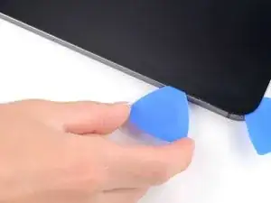
Insert the tip of an opening pick into the gap.
-
-
-
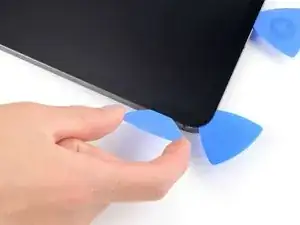
Insert a new opening pick in the gap you just created.
-
Slide the pick along the right edge to separate the adhesive.
-
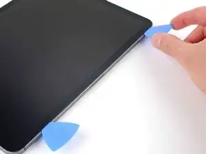
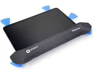
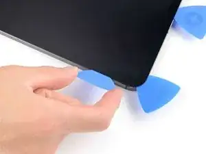
Leave the pick in the top right corner to prevent the adhesive from re-sealing.
-
-
-
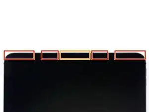
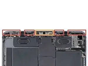
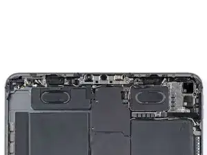
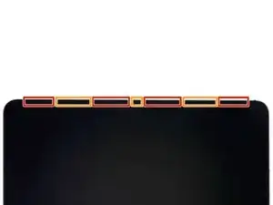
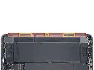
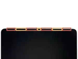
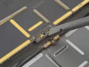
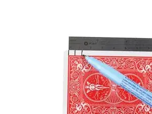
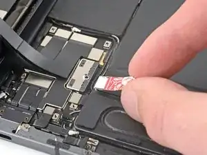
Don't insert an opening pick more than 5 mm near the top left and right edges or you'll damage the ambient light sensors.
-
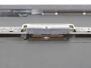
Don't insert an opening pick more than 1 mm near the middle of the top edge or you'll damage the camera module.
-
-
-
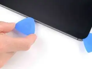
Insert a new opening pick in the gap you just created.
-
Slide the pick along the top right edge, stopping when you reach the right ambient light sensor.
-
Leave the pick in to prevent the adhesive from re-sealing.
-
-
-
Insert a new opening pick to the right of the ambient light sensor.
-
Slide the pick along the middle section of the top edge, stopping when you reach the left ambient light sensor.
-
Leave the pick in to prevent the adhesive from re-sealing.
-
-
-
Insert a new opening pick to the left of the ambient light sensor.
-
Slide the pick along the top left edge, stopping when you reach the left ambient light sensor.
-
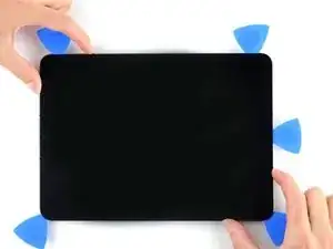
Once the top edge adhesive has been separated, you can remove the two picks near the ambient light sensors.
-
-
-
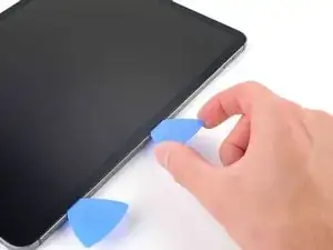
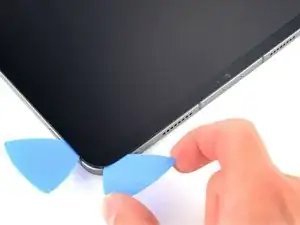
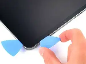
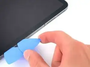
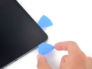
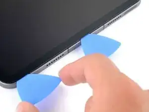
Insert a new opening pick in the bottom right corner below the existing pick.
-
Slide the pick around the bottom right corner to separate the adhesive.
-
-
-
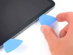
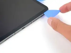
Slide the opening pick along the bottom edge, stopping at the USB-C port.
-
Leave the pick in to prevent the bottom edge adhesive from re-sealing.
-
-
-
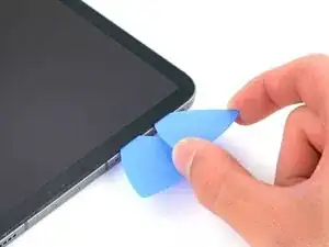
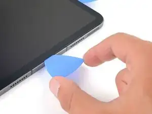
Insert a new opening pick to the left of the USB-C port.
-
Separate the remaining bottom edge adhesive.
-
Leave the pick in the bottom left corner to prevent the bottom edge adhesive from re-sealing.
-
-
-
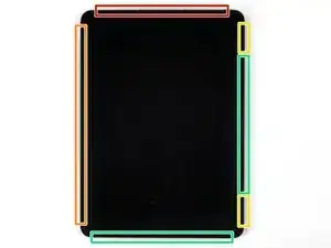
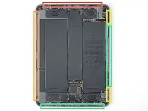
The display cables are located within small indents of the frame and require an opening pick to be inserted at a 45° angle.
-
There are flat sections of the frame which require an opening pick to be inserted horizontally.
-
-
-
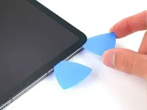
Insert an opening pick at a 45˚ angle just above the bottom left corner.
-
Carefully slide the pick along the left edge, stopping when you reach the flat section of the frame.
-
-
-
Lower the opening pick so it is horizontal to the screen.
-
Continue separating the left edge adhesive until you reach the next indented section of the frame.
-
-
-
Separate the remaining adhesive, making sure to follow the instructions exactly as written.
-
Slide the pick at a 45˚ downward angle and don't insert the pick more than 5 mm.
-
Slide the pick horizontally and don't insert the pick more than 5 mm.
-
-
-
Use an opening pick to remove any remaining adhesive keeping the screen stuck to the frame.
-
Grab the top right and bottom left corners of the screen.
-
Slowly slide the screen towards the bottom right corner to separate it from the frame.
-
Shift the screen towards the bottom right corner of the frame until the ambient light sensor ribbon cable near the top edge is uncovered.
-
-
-
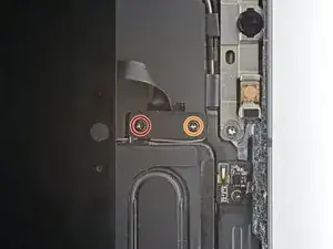
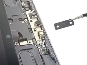
Use a Phillips screwdriver to remove the two screws securing the ambient light sensor cable bracket to the logic board:
-
One 1.3 mm screw
-
One 2.0 mm screw
-
-
-
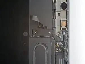
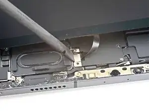
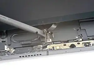
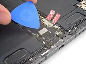
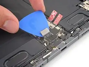
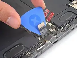
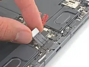
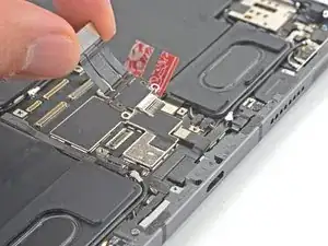
Use the flat end of a spudger to disconnect the ambient light sensor cable by lifting straight up on the press connectors.
-
-
-
Grip the right edge of the screen and fold it open like a book.
-
Lay the screen down over the left edge of the iPad.
-
-
-
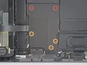
Use a Phillips screwdriver to remove the five 1.2 mm screws securing the lower cable shield to the logic board.
-
Two 2.0 mm screws
-
Three 1.3 mm screws
-
-
-
Use a Phillips screwdriver to remove the 1.8 mm screw securing the battery connector to the logic board.
-
-
-
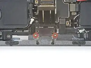
Use a Phillips screwdriver to remove the two 1.9 mm screws securing the USB-C port to the frame.
-
Compare your new replacement part to the original part—you may need to transfer remaining components or remove adhesive backings from the new part before installing.
To reassemble your device, follow these instructions in reverse order.
Take your e-waste to an R2 or e-Stewards certified recycler.
Repair didn’t go as planned? Try some basic troubleshooting, or ask our iPad Pro 11" 3rd Gen Answers community for help.
