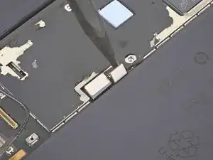
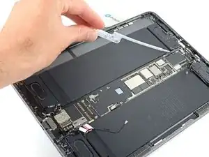
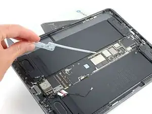
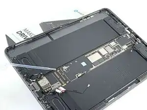
Einleitung

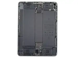
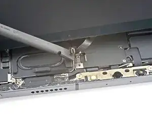
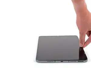
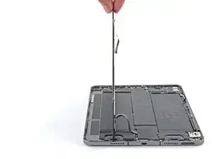
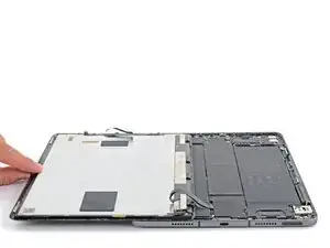
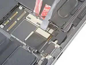
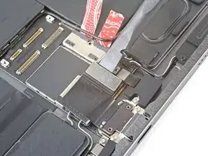
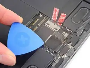
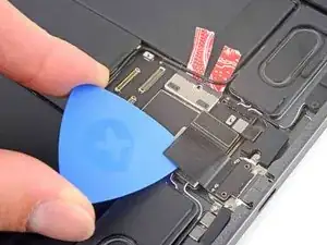
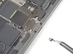
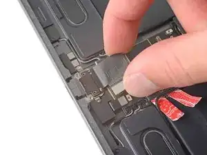
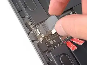
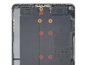
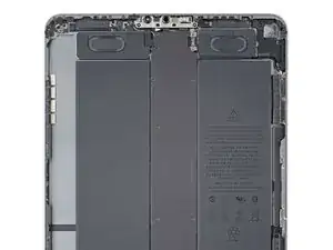
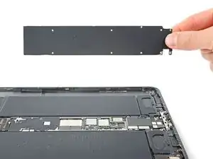
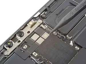
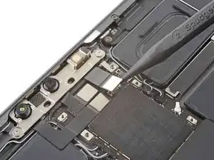
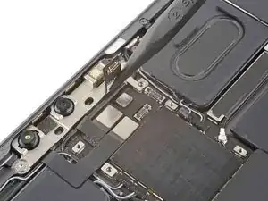
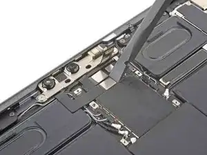
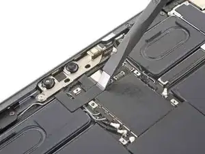
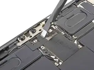
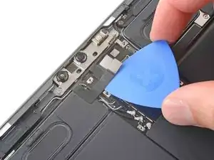
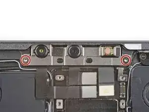
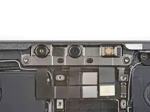
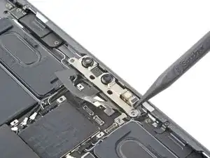
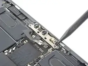
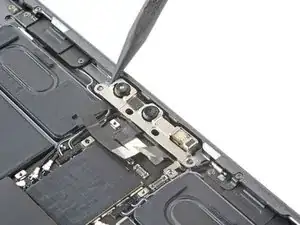
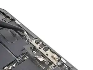
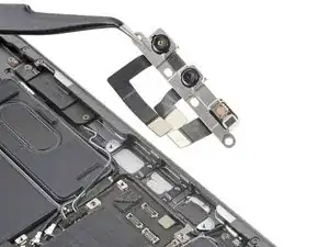
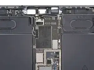
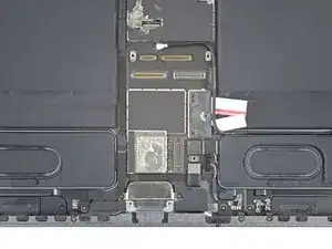
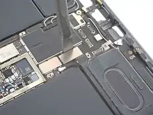
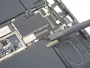
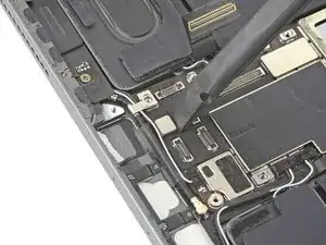
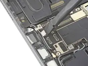
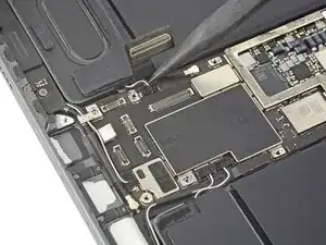
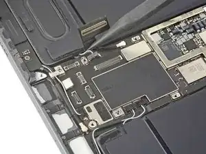
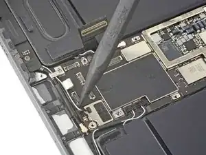
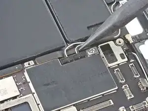
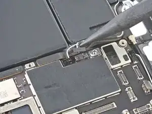
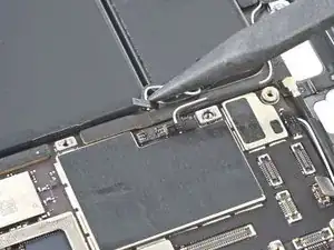
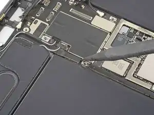
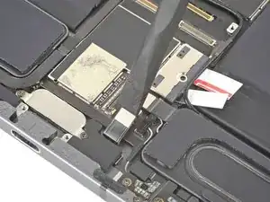
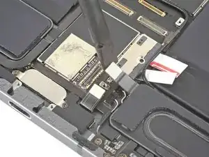
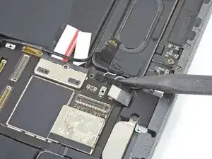
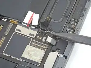
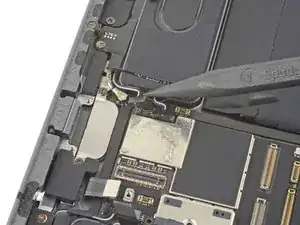
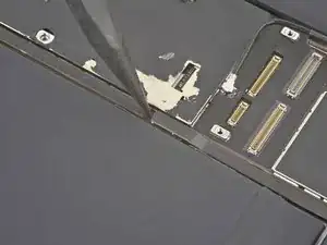
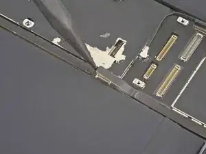
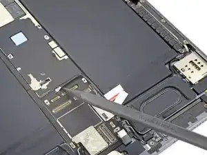
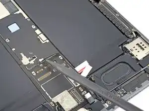
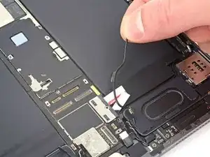
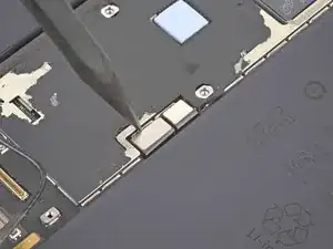
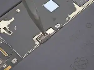
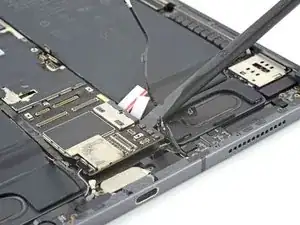
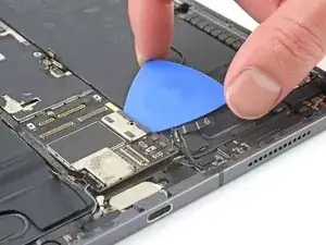
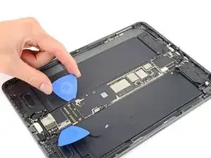
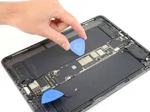
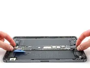
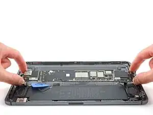
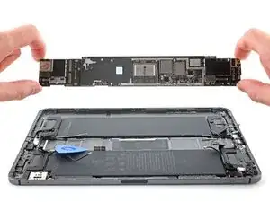
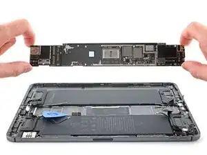
Follow this guide to replace the logic board in your iPad Pro 11" 1st Gen.

The logic board in your iPad Pro is paired to the Face ID hardware. Replacing it will disable Face ID.

This guide is written with an A2013 (Wi-Fi + Cellular) and an A2301 (Wi-Fi + Cellular + mmWave) iPad Pro. If you're fixing a Wi-Fi model, you can still use this guide—there will be some visual discrepancies, and you'll need to skip the steps related to the cellular antennas.

  1. YWVxO1movQWwpRq4
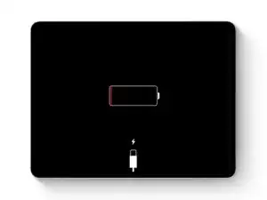
    • Allow your iPad's battery to fully drain before starting this repair. A charged battery may catch fire if damaged during the repair.

    • Unplug any cables and fully shut down your iPad.

  2. 4lFpYMSDZhNCsewN
    4lFpYMSDZhNCsewN
    BlORMsjOEwTfsGYp
    3gKBmMoBC4IqKoKi
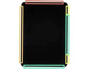
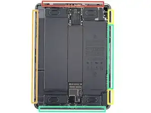
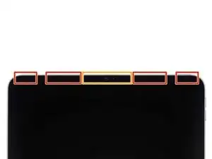
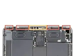
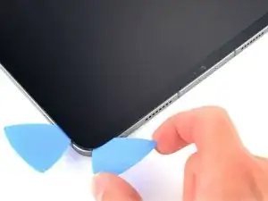
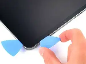
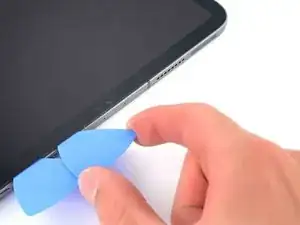
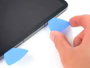
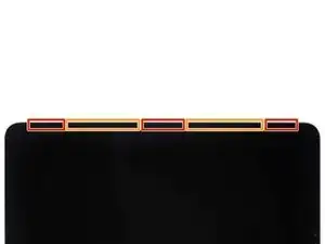
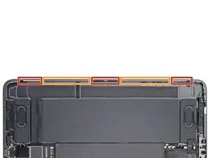
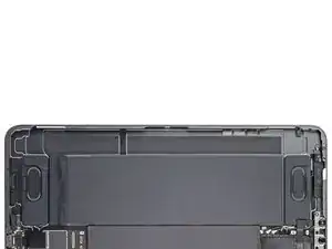
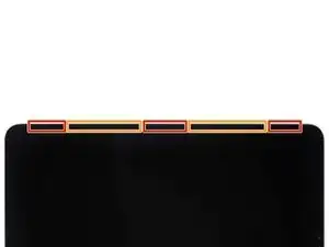
    • While your iPad looks uniform from the outside, there are delicate components under portions of the screen. To avoid damage, follow instructions exactly as written and note the following areas as you open your iPad:

    • Camera module and ambient light sensors

    • Display cables

    • Screen magnets

    • LCD edges

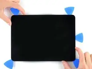
  3. SWfJNvV3tpPHfafG
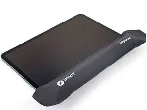
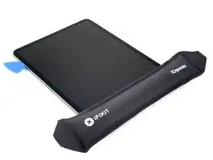
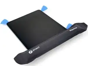
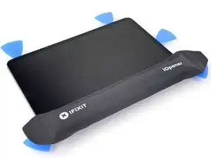
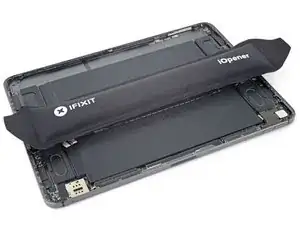
    • Apply a heated iOpener to the right edge of the screen for two minutes.

    • You can also use a hair dryer, heat gun, or hot plate—but extreme heat can damage the screen and/or internal battery, so proceed with care.

  4. TTL3hUSgQ2dTT15M
    TTL3hUSgQ2dTT15M
    y3IIejR5NOMZqJ1m
    51UcPX4FDkG641NG
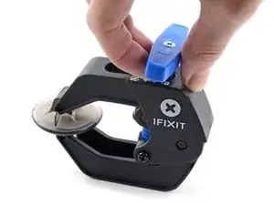
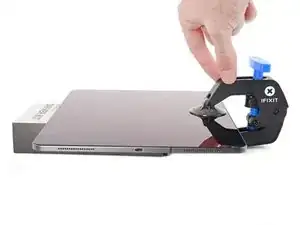
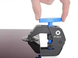
    • The next two steps demonstrate the Anti-Clamp, a tool we designed to make the opening procedure easier. If you aren't using the Anti-Clamp, skip down two steps for an alternate method.

    • For complete instructions on how to use the Anti-Clamp, check out this guide.

    • Pull the blue handle towards the hinge to disengage opening mode.

    • Elevate the iPad enough for the Anti-Clamp's arms to rest above and below the screen.

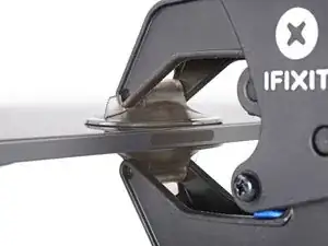
    • Position the suction cups near the right edge of the iPad—one on the front, and one on the back.

    • Push down on the cups to apply suction to the desired area.

    • If you find that the surface of your device is too slippery for the Anti-Clamp to hold onto, you can use packing tape to create a grippier surface.

  5. KOD13BqFMcU3xA1j
    KOD13BqFMcU3xA1j
    Gofvc2d5ZvwIn4UK
    PXumh5n6Dgn5uExw
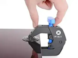
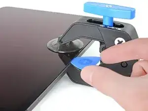
    • Push the blue handle away from the hinge to engage opening mode.

    • Turn the handle clockwise until you see the cups start to stretch.

    • Make sure the suction cups remain aligned to each other. If they begin to slip out of alignment, loosen the suction cups slightly and realign the arms.

    • Wait one minute to give the adhesive a chance to release and present an opening gap.

    • Insert an opening pick under the screen when the Anti-Clamp creates a large enough gap.

    • If the Anti-Clamp doesn't create a sufficient gap, apply more heat to the area and rotate the handle clockwise half a turn.

    • Don't crank more than a half a turn at a time, and wait one minute between turns. Let the Anti-Clamp and time do the work for you.

    • Skip the next step.

  6. UudD4HWgdf6lDhBA
    UudD4HWgdf6lDhBA
    tpVS1HUCPF3rsvFs
    y5AHt5ojeGJ5sKMG
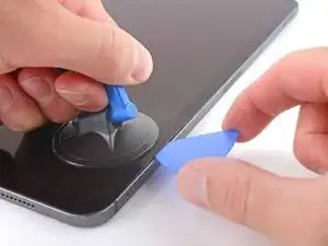
    • If your screen is badly cracked, covering it with a layer of clear packing tape may allow the suction cup to adhere. Alternatively, very strong tape may be used instead of the suction cup. If all else fails, you can superglue the suction cup to the broken screen.

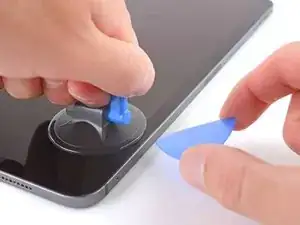
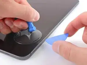
    • Apply a suction handle to the right edge of the screen, about 5 cm from the bottom edge.

    • Pull up on the suction handle with firm, constant pressure to create a gap large enough to insert an opening pick.

    • Only create a gap small enough to insert an opening pick. Overbending the screen will damage it.

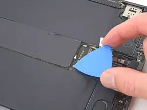
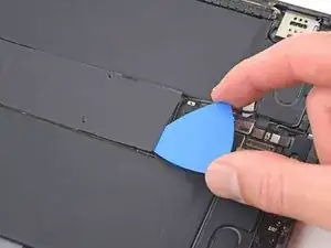
    • Insert the tip of an opening pick into the gap.

    • Don't insert the opening pick more than 5 mm or you'll damage the LCD.

  7. gKQcNDfaXmlg5WJr
    gKQcNDfaXmlg5WJr
    MBpw1FqIkISOBgaF
    PMrdneUcwwTAQbZX
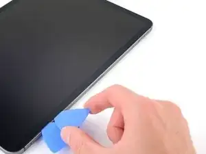
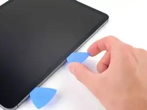
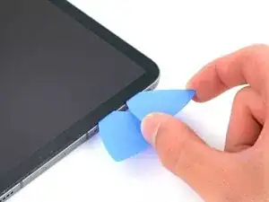
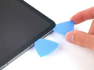
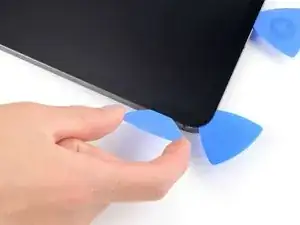
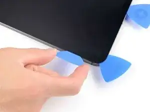
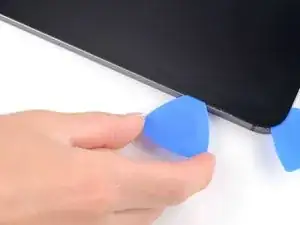
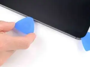
    • Insert a new opening pick in the gap you just created.

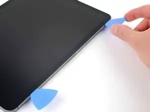
    • Slide the pick along the right edge to separate the adhesive.

    • When sliding near the volume buttons, don't insert the pick more than 2 mm or you'll damage the screen magnets.

    • Leave the pick in the top right corner to prevent the adhesive from re-sealing.

  8. aSAPlEm3Caw4yTrM
    • Apply a heated iOpener to the top edge of the screen for two minutes.

  9. dluvmXU6hUMdTkPG
    dluvmXU6hUMdTkPG
    VfZpUqLSwMjXvq5N
    PYDD3wwWHroKZ3Xu
    • The top edge of the iPad contains the camera module and two ambient light sensors. These components are fragile and easily damaged if an opening pick is inserted too far. Only separate the adhesive in the marked locations to avoid damage.

    • The two ambient light sensors can be hard to see and can be located using a flashlight or by placing the iPad under a bright light.

    • Don't insert an opening pick more than 5 mm near the top left and right edges or you'll damage the ambient light sensors.

    • Don't insert an opening pick more than 1 mm near the middle of the top edge or you'll damage the camera module.

  10. X4ERXwlrTnfpPamA
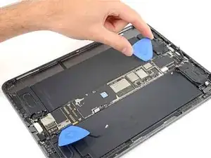
    X4ERXwlrTnfpPamA
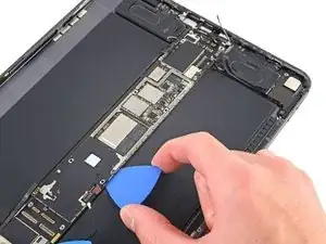
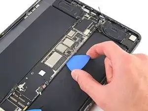
    DnQAY3CsT4PdiRdF
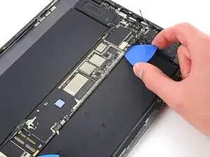
    • Insert a new opening pick in the gap you just created.

    • Slide the pick along the top right edge, stopping when you reach the right ambient light sensor.

    • Don't insert the opening pick more than 5 mm.

    • Leave the pick to the right of the sensor to prevent the adhesive from re-sealing.

  11. MSlUONmmoqsYWGpG
    MSlUONmmoqsYWGpG
    OqDYIwFnaCmVCN6g
    AswnMuPEcO2JiM5C
    • Insert a new opening pick to the right of the ambient light sensor.

    • Slide the pick along the middle section of the top, stopping when you reach the left ambient light sensor.

    • Don't insert the pick more than 1 mm or you'll damage the camera module.

    • Leave the pick in to prevent the adhesive from re-sealing.

  12. oPYYrsL54NpdCwFJ
    oPYYrsL54NpdCwFJ
    nZLYAslhDhm1nvCI
    • Insert a new opening pick to the left of the ambient light sensor.

    • Slide the pick along the top left edge, stopping when you reach the left ambient light sensor.

    • Don't insert the opening pick more than 5 mm.

    • Once the top edge adhesive has been separated, you can remove the two picks near the ambient light sensors.

  13. M4QlliPhG13xJHQW
    • Apply a heated iOpener to the bottom edge of the screen for two minutes.

  14. 45WV5NHKBLSSQjmA
    45WV5NHKBLSSQjmA
    kfyWxXwmTIoaycAR
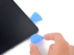
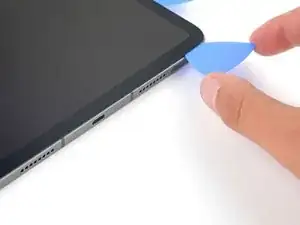
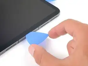
    • Insert a new opening pick in the bottom right corner below the existing pick.

    • Don't insert the opening pick more than 2 mm when sliding on the right edge.

    • Slide the pick around the bottom right corner to separate the adhesive.

  15. ZfcRVWBmGZ2joXtW
    ZfcRVWBmGZ2joXtW
    YpQXhA3yINtV4NLv
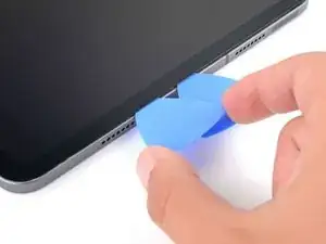
    • Slide the opening pick along the bottom edge, stopping at the USB-C port.

    • Don't insert the opening pick more than 5 mm when separating the bottom edge adhesive.

    • Leave the pick in to prevent the bottom edge adhesive from re-sealing.

  16. SCS1DRKPEyojXcQr
    SCS1DRKPEyojXcQr
    RdHjD4ZJxPPoDoZX
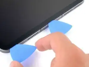
    • Insert a new opening pick to the left of the USB-C port.

    • Separate the remaining bottom edge adhesive.

    • Don't insert the opening pick more than 5 mm when separating the bottom edge adhesive.

    • Leave the pick in the bottom left corner to prevent the bottom edge adhesive from re-sealing.

  17. BBRHcwn6APDESJMU
    • Apply a heated iOpener to the left edge of the screen for two minutes.

  18. FA5ViMSIQ4Ewl6UI
    FA5ViMSIQ4Ewl6UI
    Xn2lkJPYDqJO1dYT
    trrUGpWPhLDDDwSY
    • The left edge of the iPad contains several display cables. These cables are extremely fragile and easily damaged if an opening pick is inserted too far or at the wrong angle. Follow the instructions exactly as written to avoid damage.

    • The display cables are located within small indents of the frame and require an opening pick to be inserted at a 45° angle.

    • There are flat sections of the frame which require an opening pick to be inserted horizontally.

  19. fFSKShSGUIXXRGEH
    fFSKShSGUIXXRGEH
    oG4S2tOjoD2XxPXA
    • Insert an opening pick at a 45˚ angle just above the bottom left corner.

    • Don't insert the pick more than 5 mm or you'll damage the display cables.

    • Carefully slide the pick along the left edge, stopping when you reach the flat section of the frame.

  20. sB62OFGs4RLtyKwE
    sB62OFGs4RLtyKwE
    bNHEJkP1QbVBx3Le
    • Lower the opening pick so it is horizontal to the screen.

    • Don't insert the pick more than 5 mm.

    • Continue separating the left edge adhesive until you reach the next indented section of the frame.

  21. 2fhELNUbTqZKHXJh
    • Separate the remaining adhesive, making sure to follow the instructions exactly as written.

    • Slide the pick at a 45˚ downward angle and don't insert the pick more than 5 mm.

    • Slide the pick horizontally and don't insert the pick more than 5 mm.

  22. tcFjW3mSfk3T31YN
    tcFjW3mSfk3T31YN
    v1n2MwlpuNvDlIsY
    IIudrJAeypqJXvKM
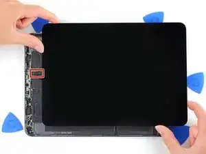
    • Grab two opposing corners of the screen and gently separate the rest of the adhesive.

    • Don't fully remove the screen as it is held in place by several ribbon cables underneath.

    • Shift the screen towards the bottom right corner of the frame until the ambient light sensor ribbon cable near the top edge is uncovered.

  23. eV4OvPRVSBIcp1tY
    eV4OvPRVSBIcp1tY
    YqSXR1xECAUeGEpw
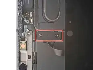
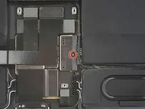
    • Throughout this repair, keep track of each screw and make sure it goes back exactly where it came from.

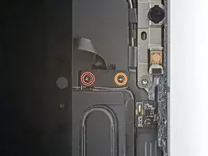
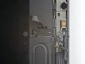
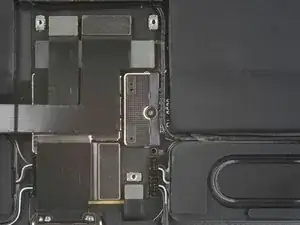
    • Use a Phillips screwdriver to remove the two screws securing the ambient light sensor cable bracket to the logic board:

    • One 1.3 mm screw

    • One 2.0 mm screw

    • During reassembly, this is a good point to power on your iPad and test all functions before sealing it up. Be sure to power your iPad back down before you continue working.

  24. wg1fGoMjlmJVL5aI
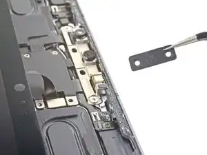
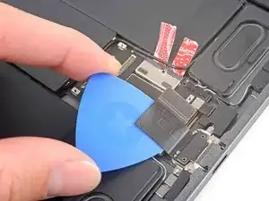
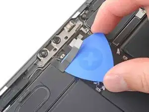
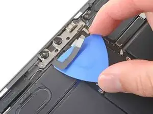
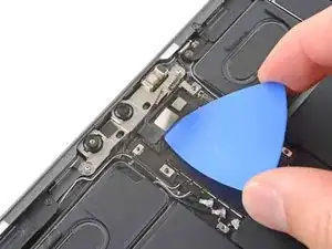
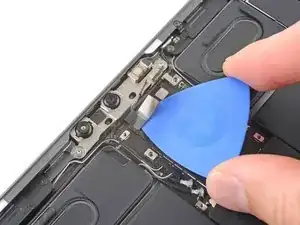
    • Use tweezers or your fingers to remove the bracket.

  25. 6ZrxyCxJShZWSVbx
    6ZrxyCxJShZWSVbx
    DnnoCmSipQ5uYkJI
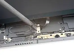
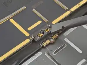
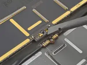
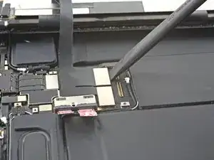
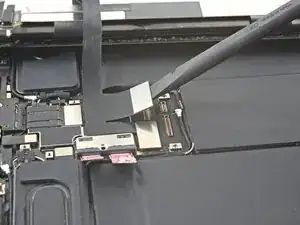
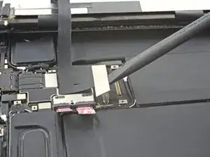
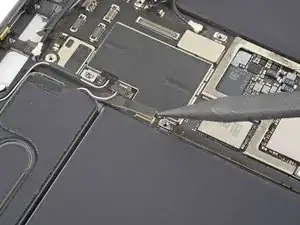
    • Use the flat end of a spudger to disconnect the ambient light sensor cable by lifting straight up on the press connector.

    • To re-attach press connectors like this one, carefully align and press down on one side until it clicks into place, then repeat on the other side. Do not press down on the middle. If the connector is misaligned, the pins can bend, causing permanent damage.

  26. NejYRMNOxSFxrBuR
    NejYRMNOxSFxrBuR
    5PWXb6IRNv6GQxvu
    jutHpQmBENyNKJAA
    • Don't try to remove the screen yet, as it's still attached by delicate ribbon cables.

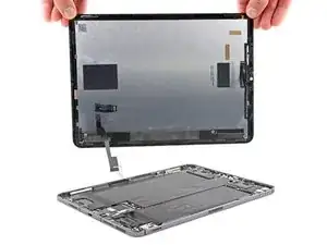
    • Grip the right edge of the screen and fold it open like a book.

    • Lay the screen down over the left edge of the iPad.

  27. WGgtPtoFurUUyFHQ
    WGgtPtoFurUUyFHQ
    SJDoQKa6SJjNiwfW
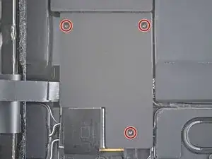
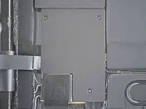
    • Use a Phillips screwdriver to remove the three 1.2 mm screws securing the bottom cable shield to the logic board.

  28. HX2WHfkpPscTGHet
    HX2WHfkpPscTGHet
    axgV6WnQeu5swxsC
    1evRVqJBSmKsTfGo
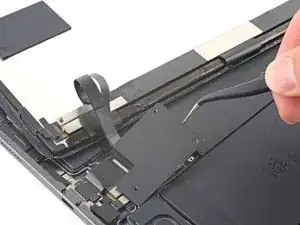
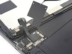
    • Use tweezers or your fingers to remove the bottom cable shield.

  29. 3yMUVEdk44LgDmoI
    3yMUVEdk44LgDmoI
    dXeVUMv1mBbYlGPf
    • Use a Phillips screwdriver to remove the 1.8 mm screw securing the battery connector to the logic board.

  30. cFKUAfdvpwFiohVS
    cFKUAfdvpwFiohVS
    43OMVHMyppnRLA4K
    JoM1pqOr1nerA5RZ
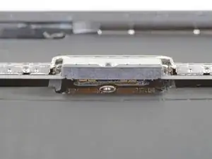
    • These photos show what the battery connector looks like underneath the logic board. Use these photos as a reference while you safely disconnect the battery.

    • Notice that the battery connector has cantilever springs on the logic board that press against the battery contact pads. Since both the logic board and battery are glued down, you'll need to slide something thin and flexible between the contact points to disconnect the battery.

  31. JsPsrZl5TyW2BOOQ
    JsPsrZl5TyW2BOOQ
    tBPo2sCL5r6YLdSA
    CAeXYc2bSyv2peRI
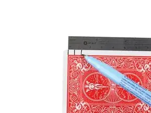
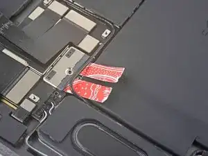
    • Cut two 6 mm wide strips from a playing card or cardstock to use as a battery blocker.

    • The strips should be about 4 cm long so you can easily grip them.

  32. BNMp6GZqyYUSG6TF
    BNMp6GZqyYUSG6TF
    ACxGPqs15ihAedjy
    i4KVQ2Hbi5OmsGxx
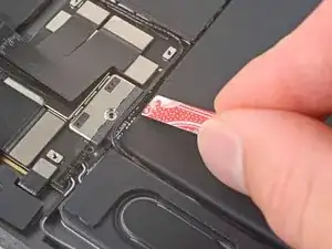
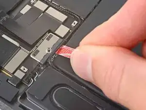
    • Insert the card strips on each side of the battery connector until they stop.

    I would like to add a bit of advice when it comes to isolating the battery from the board. As a repair tech, I recommend you insert a guitar pick next to the battery connector, rather than wedging something directly in between the battery and the connector, as you run the risk of damaging the connector. I see this happen fairly often amongst new techs and DIY-ers. If the battery connector does get damaged, it may result in the device not showing proper battery percentage (as in its a 1% all of the time) or the device may not power back on. If it does get damaged, it is completely fixable. But that should be carried out by a someone skilled in micro soldering.

    Jesse Hooton -

  33. hb4aWKRHCDmmSRVB
    hb4aWKRHCDmmSRVB
    B3Xy2Vxj4eK5lSVE
    cVNQAyeKgZnZyBTC
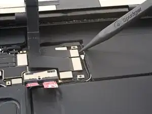
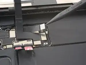
    • Use the pointed end of a spudger to pry up and disconnect the top two display cables.

  34. ZbHWsCPOofIWHcNt
    ZbHWsCPOofIWHcNt
    tJApCQr5ufqJPfiP
    bsoH3fv41niYEysg
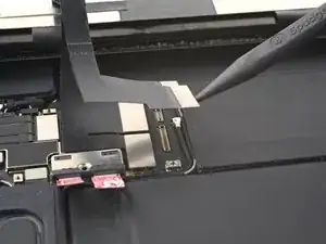
    • Disconnect the two remaining display cables.

  35. dnQviK5MA3rPPWbO
    • Grip the right edge of the screen and lift it away.

    • During reassembly, before installing a display, remove any remaining adhesive from the frame, and clean the glued areas with high-strength (>90%) isopropyl alcohol and a lint-free cloth. This helps prep the iPad for fresh adhesive and ensures that it will bond properly.

    • If you plan to reinstall your existing screen, remove any remaining adhesive from the back and clean the adhered areas with isopropyl alcohol.

    • Follow this guide to install pre-cut adhesive strips on your iPad before sealing it up.

  36. PeoHQx1RJv1Evete
    PeoHQx1RJv1Evete
    q26DH6HIGNHKuPJg
    • Use the flat end of a spudger to disconnect the USB-C port cable.

  37. ZFWc1DNYIJebD1uO
    ZFWc1DNYIJebD1uO
    23q4DwnTPrnqbSvJ
    dFrIpg4MMwATJwP5
    • The USB-C port cable is secured to the logic board with weak adhesive.

    • Slide an opening pick between the cable and the logic board to separate the adhesive.

  38. eBF4G4rxyhChncKM
    eBF4G4rxyhChncKM
    2TKic1CRhiU3OZYN
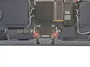
    • Use a Phillips screwdriver to remove the two 1.9 mm screws securing the USB-C port to the frame.

  39. PCFBlCbqiEA2IEsE
    PCFBlCbqiEA2IEsE
    clZbkiBFbUntdTnT
    IuLb65SCVg2aLTcG
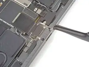
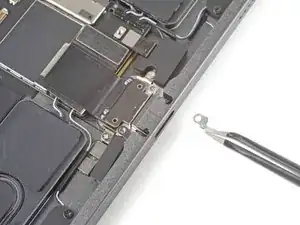
    • Use tweezers to remove the two grounding contacts from each side of the USB-C port.

  40. TtGXS4fTClHSnISA
    TtGXS4fTClHSnISA
    kufrZwyGA5W5hPGw
    • Lift the USB-C port out of its slot in the frame.

  41. Qytp3hWHVPbFQeTZ
    Qytp3hWHVPbFQeTZ
    5VU1dG1rayQiV5pl
    • Use a Phillips PH00 screwdriver to remove the eight screws securing the shield to the logic board:

    • Five 2 mm screws

    • Three 1.2 mm screws

  42. Qi5jGYnb6hwPQahK
    • Apply a heated iOpener to the top of the logic board for two minutes.

  43. R2Pm4wunJHGRrIpU
    R2Pm4wunJHGRrIpU
    xZN1vnGsqZSboLRe
    5tGQ1CKk2cMdaeIk
    • Insert an opening pick between the shield and the shielding gasket on the bottom edge of the logic board.

    • Slide the pick along the bottom edge to separate the adhesive.

  44. PXKLLBmAcLv6mcxl
    PXKLLBmAcLv6mcxl
    q2wZQAPIQaQEZRap
    SJcwBJtVCETYqiLY
    • Repeat the previous step for the right edge of the logic board shield.

  45. v1GplQCoeoLRrO3u
    v1GplQCoeoLRrO3u
    srAscC3iGvaqgolZ
    UuLGNJbmOyOMjLOD
    • Repeat the previous step for the left edge of the logic board shield.

  46. 2uY3ALS1I3JIHXmq
    2uY3ALS1I3JIHXmq
    Y34M13IGbVuvIysd
    PfL2M24MklaB4EqI
    • Grip the logic board shield at the top and lift it up.

    • Stop lifting if the shield is stuck or begins to bend—a bent shield will reduce thermal transfer from the logic board. Use an opening pick to separate any remaining adhesive.

  47. uWuBhdTPxXZncW1k
    uWuBhdTPxXZncW1k
    JRHUCwPNPRK4I1wU
    6x5FlaYlqJ5sQMyP
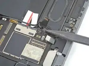
    • Use the pointed end of a spudger to disconnect the IR dot projector cable.

  48. 2OVPwqjc5khw6wRK
    2OVPwqjc5khw6wRK
    UTKYeZF2tUMTHuJQ
    auDBSWtJTeOqSwiN
    • Use the pointed end of a spudger to disconnect the front-facing camera and Face ID camera.

  49. gxyi5pqBKSahJDKR
    gxyi5pqBKSahJDKR
    2PwL2ElB6S2LUsSQ
    ty3afNaHNhsq56XY
    • The IR camera cable is secured to the logic board with weak adhesive.

    • Slide an opening pick between the IR camera cable and the logic board to separate it.

  50. 4bOwBP1EJXMydVUy
    4bOwBP1EJXMydVUy
    kVYxM3khhpsYtMOm
    x4o3XUvavo1X4fYB
    • Repeat the previous step for the camera cable.

  51. dcb1SSHgXlP4wIQi
    dcb1SSHgXlP4wIQi
    DKtaVCdkqMrSnyUV
    • Use a Torx T3 screwdriver to remove the two 2.1 mm screws securing the front camera assembly to the frame.

  52. XRP1QXKvKpPcvTXb
    XRP1QXKvKpPcvTXb
    WJQG1rlHoDX1lEq1
    NFNLUuorDZnbIJHv
    • Use the pointed end of a spudger to pry up and loosen the front camera assembly.

  53. MeoNaGAp3gduWCyd
    MeoNaGAp3gduWCyd
    qWUoeSshtHSc5dNJ
    • Use tweezers or your fingers to remove the front camera assembly.

  54. ONGQR65ELNRuBwEg
    ONGQR65ELNRuBwEg
    31uvdNhIE3ioNtcn
    • You're about to disconnect many connectors from the top and bottom of the logic board. During reassembly, use these photos as a reference to ensure all cables are connected in the correct locations.

  55. CQKGUcP4dA1aVlMe
    CQKGUcP4dA1aVlMe
    XINYaEkeFjHoKHZW
    Ov23Zp1eRDCeIpa1
    • Use the flat end of a spudger to disconnect the rear camera interconnect cable.

    • Fold the interconnect cable over so the top right speaker cable is accessible.

  56. 162iE2YBB4WrTmr5
    162iE2YBB4WrTmr5
    KEgtpmXoXosYaa4Z
    • Use the flat end of a spudger to disconnect the top microphone cable.

  57. IBDwikNdgSKqoWCT
    IBDwikNdgSKqoWCT
    5MOAqhQgSQWhbNfU
    kVNjME6SVVodNHwq
    • Use the pointed end of a spudger to disconnect the two cables for the top right speaker.

    • Avoid prying against the short sides of the connector. The socket on the logic board is delicate and may break off if pried against.

  58. 13MOVFDfE6VIaAwn
    13MOVFDfE6VIaAwn
    bpCLsCiOGZakbAGS
    TRnWdloaAUYB2Wb2
    • Repeat the previous step for the two top left speaker cables.

  59. FWDD56yKEjUOOdWC
    FWDD56yKEjUOOdWC
    tPThHnQ1J25hUCbX
    • Use the pointed end of a spudger to disconnect the top interconnect board.

    • Don't bend or reposition the interconnect board, as it will break if stressed.

  60. UdCsBShiStDcVsCG
    UdCsBShiStDcVsCG
    YA3KETL14g2NbZsB
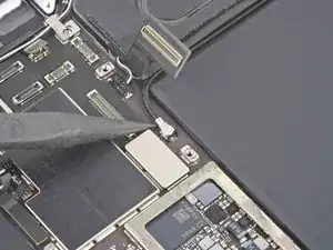
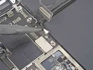
    • To disconnect antenna cables like this, use tweezers to grip the connector near the cable and lift it up.

    • Use the pointed end of a spudger to disconnect the top Wi-Fi antenna cable.

    • To reinstall, hold the connectors in place and gently press them straight down. The connectors “snap” into their sockets much like the metal snaps on a jacket.

  61. itRvNHIMFy4lkKED
    itRvNHIMFy4lkKED
    N4ocN1pLWmHRMrvA
    AOXT6faV4LBJcZnP
    • Use the flat end of a spudger to disconnect the Smart Connector and SIM card reader cables.

    • For the Wi-Fi only model there is no SIM card reader cable.

  62. IHTkU3gmOUfhuj4I
    IHTkU3gmOUfhuj4I
    WYuYqmNL6DJdGyPw
    QdPjkEl1KxQNnBV5
    • Follow the procedure in step 57 to disconnect the bottom right speaker.

  63. JXfL1f5Trsw4rjiI
    JXfL1f5Trsw4rjiI
    VajMEkwEAeW5FCLL
    JHAcGZXDXskqVYQj
    • Use tweezers to peel back the tape securing the bottom left speaker cable bracket to the logic board.

    • Slide the bracket out horizontally.

  64. YZYMlBrrmOZjNpst
    YZYMlBrrmOZjNpst
    KLD1wdSxWhcHBpTs
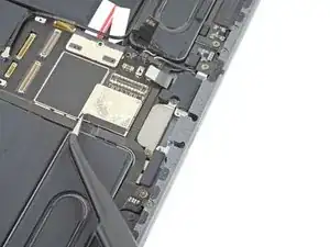
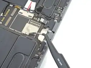
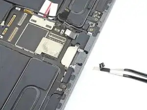
    • Use the pointed end of a spudger to disconnect the bottom left LTE wireless cable.

  65. kmxxoj3ccDuMAxvY
    kmxxoj3ccDuMAxvY
    ubMVQysJ3uauTeBa
    atKicoRuXBXkkNrk
    • Follow the procedure in step 57 to disconnect the bottom right speaker.

  66. rdD5PZyVFfZxpRhI
    rdD5PZyVFfZxpRhI
    q5HXnZXZsOgimMna
    • Follow the procedure in 59 to disconnect the bottom interconnect cable.

  67. 3kPkgCwuISdt2shv
    3kPkgCwuISdt2shv
    qER1rxLsHSFRwBXp
    WSPwKi5IiYOA5oE6
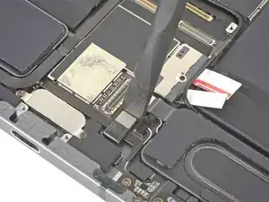
    • Use the pointed end of a spudger to disconnect the bottom Wi-Fi antenna cable.

    • Peel the cable away from the logic board and reposition it to the right.

  68. rkvSgoxZWmoWZXiI
    rkvSgoxZWmoWZXiI
    wxgOSFYSB3N3FxtY
    5vOABANJWJAjdfjn
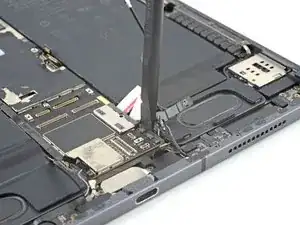
    • Use the pointed end of a spudger to disconnect the left microphone and Apple Pencil charger cables.

  69. ibny4tZ3JMCiAuGR
    ibny4tZ3JMCiAuGR
    dL2jiMgiimTMOsRW
    ayIUVB1tnDENtVgV
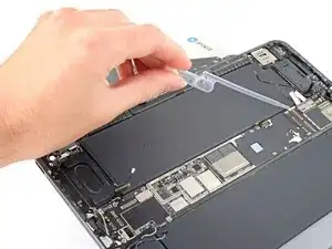
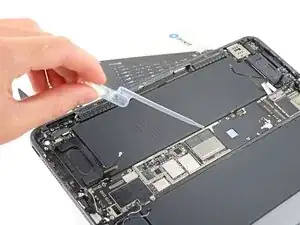
    • The adhesive that secures the logic board to the frame is very strong. To remove the board, follow the next steps to weaken the adhesive using high-strength (>90%) isopropyl alcohol.

    • Prop the left side of the iPad up against an object so the isopropyl alcohol can flow under the logic board.

    • Apply a few drops of isopropyl alcohol along the left edge of the logic board.

    • Be careful if you're using a syringe with a needle or other sharp instrument to dispense isopropyl alcohol—a punctured or bent battery may leak dangerous chemicals or cause a fire.

    • Let the alcohol soak for one minute to soften the adhesive under the logic board.

  70. QcNQNFtrcJZm1nUU
    QcNQNFtrcJZm1nUU
    6cibv366VQcePcau
    NUnJHIlY4ZNjNr6o
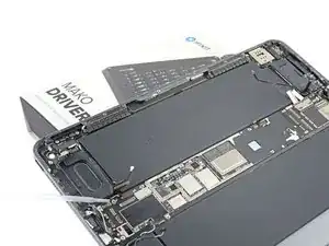
    • Rotate your iPad 180˚ and lay it down with the right side elevated.

    • Repeat the previous step for the right edge of the logic board.

  71. SNoAYG5ym66e2pa3
    SNoAYG5ym66e2pa3
    2VQ6hCJnwTtpQLML
    nrdnFA1LyKa4QJCk
    • Insert the flat end of a spudger between the logic board and the bottom right speaker.

    • Slowly pry up the bottom of the logic board.

    • If it is difficult to pry up the logic board, apply additional isopropyl alcohol and wait one minute.

    • Replace the playing card strips with an opening pick to block the battery.

  72. GBwTVg5tDg4lMB6R
    GBwTVg5tDg4lMB6R
    gtBvA3funR1yDew1
    nVLPxFxIXEQ1huOA
    • Slide an opening pick under the left edge of the logic board to loosen it.

    • Pry against the frame underneath the logic board to separate the adhesive.

    • Don't forcefully lever against the battery—a punctured or bent battery may leak dangerous chemicals or cause a fire.

    • If the adhesive is still too strong to lift up the logic board, apply some additional isopropyl alcohol and wait one minute.

  73. GrQRwERo2YW1A3BP
    GrQRwERo2YW1A3BP
    dFHStYntwiCnsEXp
    NlGEudadSLcR65KI
    • Insert an opening pick under the right edge of the logic board above the left microphone and Apple Pencil charger cables.

    • Repeat the previous step for the right side of the logic board.

  74. HLIHXvp1cROCTHUe
    HLIHXvp1cROCTHUe
    VvDd1dSMuYDZmpHu
    KtJlctsBwMvYCJUj
    • Grip the top and bottom edges of the logic board.

    • Remove the logic board.

    • Remove the old adhesive from the rear case and bottom of the logic board using tweezers and high concentration isopropyl alcohol with a lint-free cloth where needed.

    • During reassembly, apply strips of Tesa tape to the bottom of the logic board.

Abschluss

Compare your new replacement part to the original part—you may need to transfer remaining components or remove adhesive backings from the new part before installing.

To reassemble your device, follow these instructions in reverse order.

Take your e-waste to an R2 or e-Stewards certified recycler.

Repair didn’t go as planned? Try some basic troubleshooting, or ask our iPad Pro 11" 1st Gen answers community for help.
Chayton Ritter

Mitglied seit: 21/08/20

12163 Reputation

0 Kommentare