Introduction

This repair guide was authored by the iFixit staff and hasn’t been endorsed by Google. Learn more about our repair guides here.

Use this guide to replace the motherboard in your Google Pixel 7.

For your safety, discharge the battery below 25% before disassembling your phone. This reduces the risk of fire if the battery is accidentally damaged during the repair. If your battery is swollen, take appropriate precautions.

Caution: The Pixel 7 contains class 1 lasers. Disassembly could result in exposure to invisible infrared laser emissions.

Replacing the motherboard in the Google Pixel 7 requires you to remove the battery. Do not reuse the battery if it has been deformed or damaged, as doing so is a potential safety hazard. Replace it with a new battery.

This guide was made using the GQML3 model, which features a 5G mmWave antenna. If you have a non-mmWave model, you can still use this guide—just ignore the mmWave antenna steps.

Retaining water resistance after the repair will depend on how well you reapply the adhesive, but your device will lose its IP (Ingress Protection) rating.

You'll need replacement adhesive in order to complete this repair.

  1. 6cKgLNhBJSeuArNm
    • Completely power off your phone before you begin.

    • Apply a heated iOpener to the screen to loosen the adhesive underneath. Apply the iOpener for at least 3 minutes.

    • A hair dryer, heat gun, or hot plate may also be used, but be careful not to overheat the device. The edge should feel slightly too hot to the touch.

  2. uWsCCoGWV5JIrUns
    uWsCCoGWV5JIrUns
    qBuyTnEhoZIp4ycS
    rCPFaRmEDnGc6YSe
    • The screen of the Google Pixel 7 is held in place by plastic clips and adhesive.

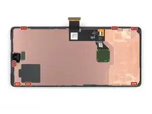
    • During the removal procedure, make sure to insert your opening picks in the right position to avoid separating the screen from its safety frame instead of the phone assembly.

    • Only insert the pick up to ~3.5 mm during the removal procedure to avoid damaging the internals and to avoid interfering with the plastic clips.

    • There are several plastic clips around the whole screen. In case your opening pick gets blocked during the screen removal procedure it means you inserted your pick too deep underneath the screen.

  3. uNWQn4O2iyarfTwP
    uNWQn4O2iyarfTwP
    44poRvbIrGwkVIPM
    3LPxiQplCRUOcbrT
    • The next two steps demonstrate the Anti-Clamp, a tool we designed to make the opening procedure easier. If you aren't using the Anti-Clamp, skip down two steps for an alternate method.

    • For complete instructions on how to use the Anti-Clamp, check out this guide.

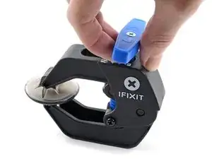
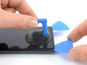
    • Pull the blue handle towards the hinge to disengage opening mode.

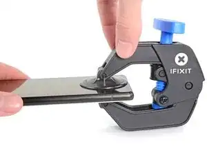
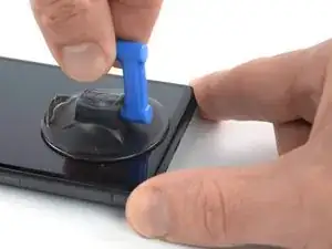
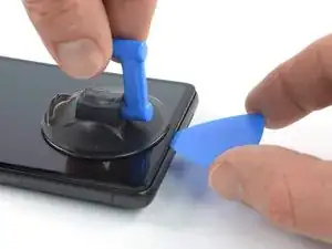
    • Position the suction cups near the bottom edge of the phone—one on the front, and one on the back.

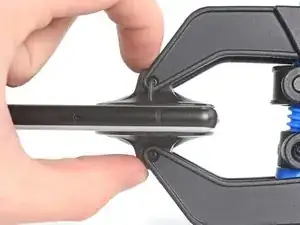
    • Push down on the cups to apply suction to the desired area.

    • If you find that the surface of your device is too slippery for the Anti-Clamp to hold onto, you can use packing tape to create a grippier surface.

  4. Np6kNAuADQBZCVEh
    Np6kNAuADQBZCVEh
    GTo2TiYJMsedkYsV
    XfQhjHLIJQsSU6BG
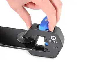
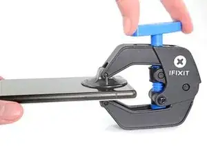
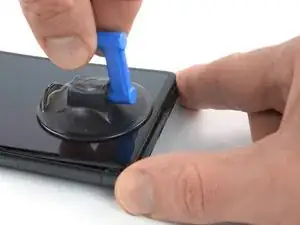
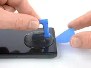
    • Push the blue handle away from the hinge to engage opening mode.

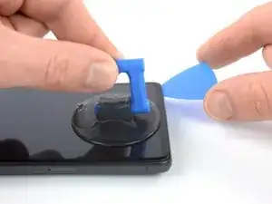
    • Turn the handle clockwise until you see the cups start to stretch.

    • Make sure the suction cups remain aligned to each other. If they begin to slip out of alignment, loosen the suction cups slightly and realign the arms.

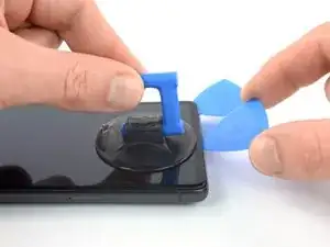
    • Wait one minute to give the adhesive a chance to release and present an opening gap.

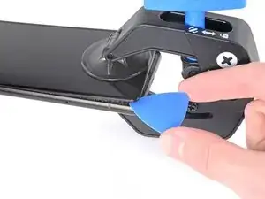
    • Insert an opening pick under the screen and its safety frame when the Anti-Clamp creates a large enough gap.

    • If the Anti-Clamp doesn't create a sufficient gap, apply more heat to the area and rotate the handle clockwise half a turn.

    • Don't crank more than a half a turn at a time, and wait one minute between turns. Let the Anti-Clamp and time do the work for you.

    • Skip the next two steps.

  5. CexARCSAqGYQbmha
    CexARCSAqGYQbmha
    4gF4DCWXWHNS2aGI
    gfaVVfZV1RGTbMLx
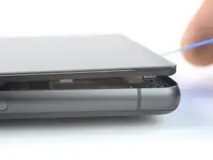
    • Once the screen is warm to the touch, apply a suction handle to the bottom edge of the screen.

    • If your display is badly cracked, covering it with a layer of clear packing tape may allow the suction cup to adhere. Alternatively, very strong tape may be used instead of the suction cup. If all else fails, you can superglue the suction cup to the broken screen.

    • Lift the screen including its safety frame with the suction handle to create a small gap between the screen and the phone assembly.

    • Depending on the age of your phone, this may be difficult. If you're having trouble, apply more heat to the bottom edge and try again.

    • Insert an opening pick into the gap.

  6. wtdv5UrUMow2CECH
    wtdv5UrUMow2CECH
    djiNoNgaVURRqAnE
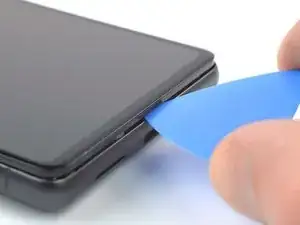
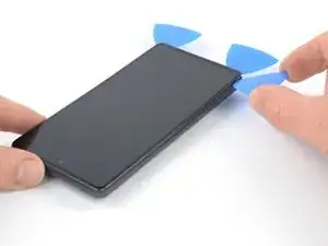
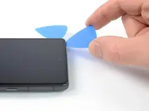
    • Slide the opening pick to the bottom right corner of the screen to slice its adhesive.

    • Leave the opening pick in place to prevent the adhesive from resealing.

  7. BvVyMHlKdFsfT4jJ
    BvVyMHlKdFsfT4jJ
    STqP6jEultQQM41x
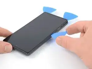
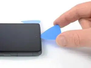
    • Insert a second opening pick at the bottom edge and slide it to the bottom left corner of the screen to slice the adhesive.

    • Leave the opening pick in place to prevent the adhesive from resealing.

  8. 3TahkFe4ry6RCiY4
    3TahkFe4ry6RCiY4
    3JU6OqcJvHWxqoST
    6ZPHWVqkfEhNxfpF
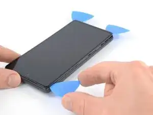
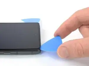
    • Insert a third opening pick underneath the bottom left corner of the screen.

    • Slide the opening pick along the left edge of the screen to slice the adhesive and to release the plastic clips.

    • Leave the opening pick in the top left corner to prevent the adhesive from resealing.

  9. RAqKHAsrl3xCRUU1
    RAqKHAsrl3xCRUU1
    snvx1NYmrDPfUDaX
    cnPPFVoxMmq3nELB
    • If the adhesive becomes hard to cut, it has most likely cooled down. Use your iOpener or heat gun for 1-2 minutes to reheat it.

    • When you slice near the front facing camera, insert only the tip of the opening pick (~2.5 mm) to avoid damaging or smearing the camera.

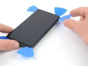
    • Insert a fourth opening pick at the top left corner of the screen.

    • Slide the opening pick along the top edge of the phone to slice the adhesive.

    • Leave the opening pick in the top right corner to prevent the adhesive from resealing.

  10. PnfIw3f25Eqr1XHF
    PnfIw3f25Eqr1XHF
    KenvqZiSWYaywVKu
    TZuqyojhZfgKo23H
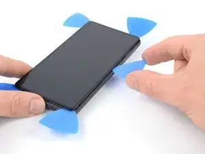
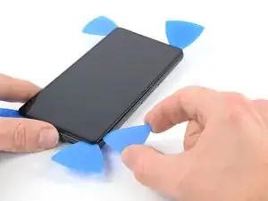
    • Insert a fifth opening pick and slide it along the right edge of the phone to slice the remaining adhesive and release the right plastic clips.

    • Do not try to remove the display all the way yet, the screen is still connected to the phone assembly by a flex cable.

  11. rhQqo5C35FvoYK3U
    rhQqo5C35FvoYK3U
    IrVMIJexBS6bDSeP
    jLlFZYjxMwL21C2X
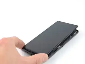
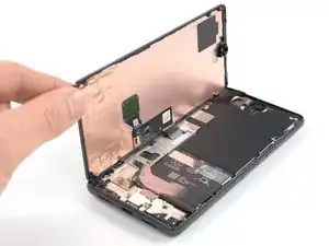
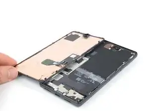
    • Lift the right edge of the screen up and towards the left side of the device, like opening a book.

    • Don't twist the screen or move it too far away from the frame to avoid straining or damaging the flex cable.

    • Rest the screen upside down and parallel to the frame before continuing.

  12. PSmtyE4SOWOdAwOu
    PSmtyE4SOWOdAwOu
    EP6lSfkEvCqupEtr
    • The display cable bracket sits tightly and requires some force to release it.

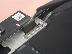
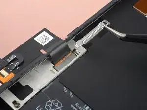
    • Insert one arm of a pair of tweezers into the opening at the upper end of the display cable bracket.

    • Push the bracket inwards and pry up to release it.

  13. WKPNiJHhVHnhCorC
    WKPNiJHhVHnhCorC
    LhAcZy62xFSngm3n
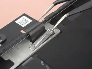
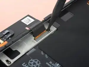
    • Use a pair of tweezers to remove the display cable bracket by pulling it from underneath the midframe and in direction of the cameras.

  14. jRnnMxxSKtAwg2aW
    jRnnMxxSKtAwg2aW
    HaPX5khLMl4bDRNB
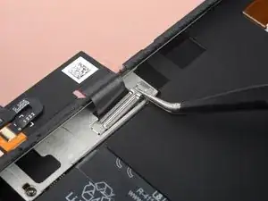
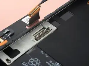
    • Use a spudger to disconnect the display flex cable by prying the connector straight up from its socket.

    • To re-attach press connectors like this one, carefully align and press down on one side until it clicks into place, then repeat on the other side. Do not press down on the middle. If the connector is misaligned, the pins can bend, causing permanent damage.

  15. BoCjkJcuFRI2e25m
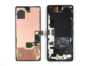
    • Separate the screen from the phone.

    • During reassembly:

    • Check that all screws are tightened and there are no loose parts.

    • Apply new adhesive where it's necessary after cleaning the relevant areas with isopropyl alcohol (>90%).

    • Follow this guide if you're using custom-cut adhesives for your device.

    • Follow this guide if you're using a pre-cut adhesive card.

    • During the boot-up process after reassembly, the screen will go through a calibration sequence. Do not touch the screen during this process, as it could result in improper touch calibration and create touch issues.

  16. 14imDI25DUIx1yGK
    14imDI25DUIx1yGK
    TFYpSGAObkMQVbOn
    56Lyx2AoExgaqrTE
    • Take care not to puncture or bend the battery with your tool in the following steps—a punctured or bent battery may leak dangerous chemicals or cause a fire.

    • Use a pair of tweezers to peel the black silicone pad off the battery and midframe.

  17. VDPIZdKfH3wuXY2B
    VDPIZdKfH3wuXY2B
    CXSDIgr4kqK4EUu3
    UVO1ulPhOufQgl1P
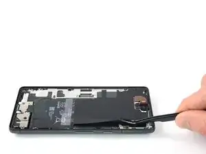
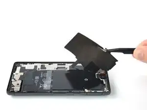
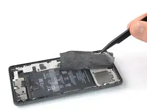
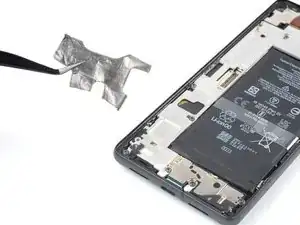
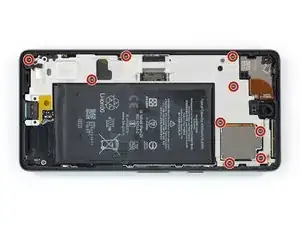
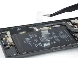
    • Use a pair of tweezers to carefully peel the upper graphite foil off the battery and midframe.

    • If you're having a hard time peeling off the foil, apply a heated iOpener to the foil for two minutes to loosen its adhesive.

  18. ViHZySMPUa3YJNXP
    ViHZySMPUa3YJNXP
    EtIxr6sbQbvRHxan
    FlDBAAhxsnmbbJaR
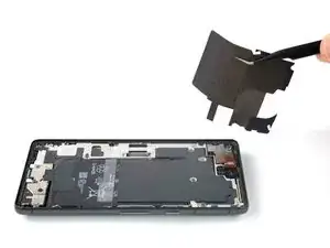
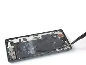
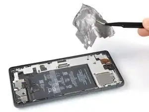
    • Use a pair of tweezers to carefully peel the lower graphite foil off the battery and midframe.

    • If you're having a hard time peeling off the foil, apply a heated iOpener to the foil for two minutes to loosen its adhesive.

  19. pbbhTvbOv51oPAWq
    pbbhTvbOv51oPAWq
    X5krQjmm3scjBR2E
    • Use a Torx T3 screwdriver to remove the three 5.1 mm-long screws securing the loudspeaker.

  20. bNE1RIGFBYEeKcqZ
    bNE1RIGFBYEeKcqZ
    wmVWfVHUkYc2kScS
    • Use a pair of tweezers to lift the loudspeaker out of its recess and remove it.

  21. JxTWHWI1ZEti1kDp
    JxTWHWI1ZEti1kDp
    tb5RIJQqmyQZGUEN
    • Use a Torx T3 screwdriver to remove the nine 5.1 mm-long screws securing the midframe.

  22. OoT3ECRbkjHTrU5U
    OoT3ECRbkjHTrU5U
    vleQwMUKxf6UlKXs
    • Use a pair of tweezers to remove the midframe.

  23. 6BrgM6SJIEyyahJY
    6BrgM6SJIEyyahJY
    AQMSn2QGAih3B6Cn
    • Use a spudger to disconnect the battery cable by prying the connector straight up from its socket.

  24. R1BnKI2OkRcyiEHk
    R1BnKI2OkRcyiEHk
    tWEgonUNF5mAjUSY
    PTygska1GvygRnJC
    • Use the flat end of a spudger to scrape the thermal paste off the motherboard.

    • Clean any remaining thermal paste with isopropyl alcohol and either a coffee filter or a lint-free cloth.

    • Repeat the cleaning process for the thermal paste on the midframe.

    • During reassembly, follow this guide for reapplying thermal paste onto the motherboard.

  25. MEBSIEQJ3cDOcppX
    • Apply a heated iOpener to the back of the device to loosen the adhesive underneath. Apply the iOpener for at least 3 minutes.

    • A hair dryer, heat gun, or hot plate may also be used, but be careful not to overheat the device. The edge should feel slightly too hot to the touch.

  26. FYPgWCphG1UMHnsN
    FYPgWCphG1UMHnsN
    OHNxRytTeLULCuGi
    l4rWPfIHHieHJmoJ
    • Use tweezers, or your fingers, to peel the plastic pull tabs away from the battery.

  27. VKtWXkejogB1FQKf
    VKtWXkejogB1FQKf
    2fRE5ec2E31Epl4a
    IGrOxwXXBfgPc21s
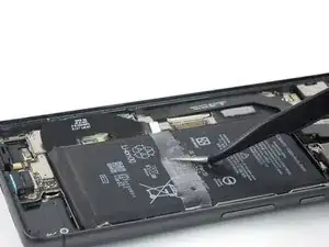
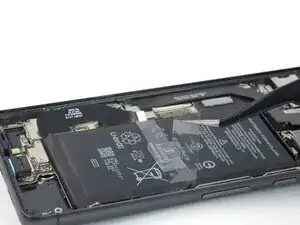
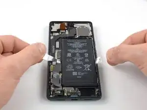
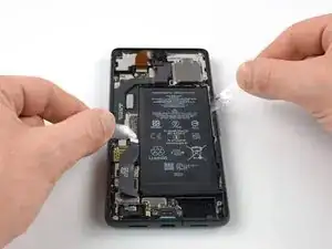
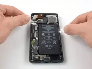
    • Pull the tabs back and forth in a sawing motion up the length of the battery to separate the adhesive underneath.

    • Work slowly. It's easy to lose your grip and accidentally pull the tab up from under the battery.

    • If you're having difficulty separating the adhesive, apply more heat and wait for the adhesive to loosen.

    • If you lose or tear the release strip, follow the next step for an alternative battery removal method.

  28. kBtRpff6NmtSHLeX
    kBtRpff6NmtSHLeX
    AIPOCWLYmqIRlHKI
    cFaCowwFmjvbDqou
    • Follow this step if you couldn't loosen the battery using the battery release strip.

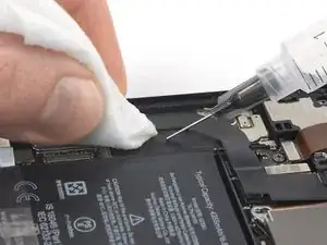
    • Apply a few drops of high concentration (90% or higher) isopropyl alcohol into the gap at the top edge of the battery.

    • Don't apply too much alcohol, or you'll loosen the NFC antenna and charging coil underneath the battery.

    • Wait about one minute for the alcohol solution to weaken the adhesive.

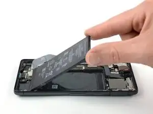
    • Use the flat end of a spudger or an opening pick to gently lift the top edge of the battery until you can grab it with your fingers.

    • Don't use excessive force on the battery. Slow, consistent pressure is all that's required to free it from the frame.

    • Take care not to puncture or bend the battery with your tool—a punctured or bent battery may leak dangerous chemicals or cause a fire.

  29. qW1YsQlIgHytFWKu
    qW1YsQlIgHytFWKu
    d2CijPPmXxQe2aZQ
    liG5k3cSY1KwfqTE
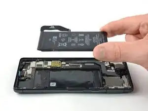
    • Tilt the battery out of the device to separate the rest of the adhesive.

    • Remove the battery.

    • Do not reinstall a damaged or deformed battery, as doing so is a potential safety hazard.

    • To secure the replacement battery:

    • Apply pre-cut adhesive adhesive or double-sided tape to the battery well at the places where the old adhesive was located, not directly onto the battery.

    • Temporarily reconnect the battery to the motherboard to help align it correctly. Disconnect the battery after it's seated.

    • Make sure that the battery sits in the center of the battery well and there's an even gap around the battery.

    • Press the new battery firmly into place.

  30. vaQE2oaO3PEg4NGG
    vaQE2oaO3PEg4NGG
    1q6OHWPZEfmqaAVI
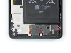
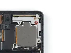
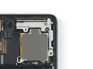
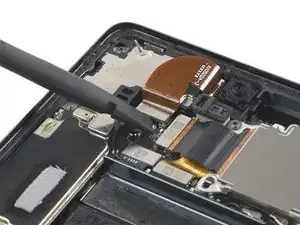
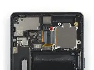
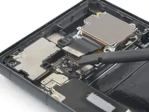
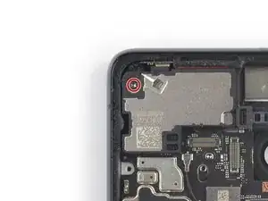
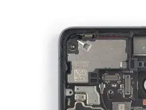
    • Use a Torx T3 screwdriver to remove the 5.1 mm-long screw securing the mmWave antenna bracket.

  31. JP2VkZZHaaNACKQh
    JP2VkZZHaaNACKQh
    gqWCswRqDmQcUly2
    • Use a pair of tweezers to remove the mmWave antenna bracket.

  32. DY6ZJUyDSY3qPYKf
    DY6ZJUyDSY3qPYKf
    4RpMMsv3phCNoDXn
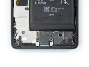
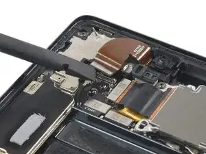
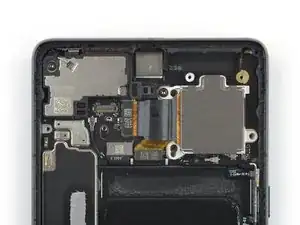
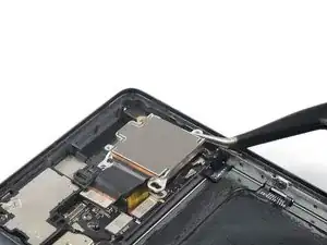
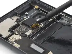
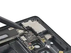
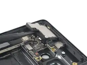
    • Use a spudger to disconnect the mmWave antenna cable by prying the connector straight up from its socket.

  33. OrQMUZWL5sxdXNKr
    OrQMUZWL5sxdXNKr
    jAK3ge5D23KUAHEv
    XaoFjCMnDTTqxvyW
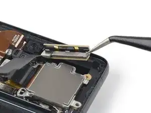
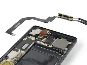
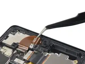
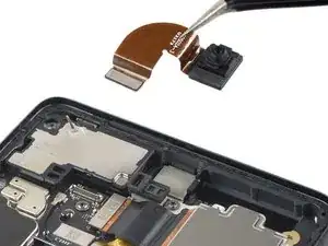
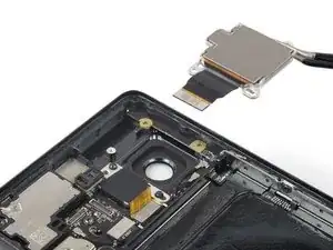
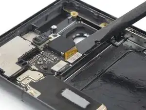
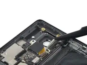
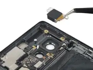
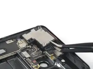
    • Use a pair of tweezers to lift the mmWave antenna including its cable out of its recess.

    • Remove the mmWave antenna assembly.

  34. bSVBqtR3yhvtARX4
    bSVBqtR3yhvtARX4
    bkltoo4kYYykIoaF
    GSAEFsUZZWWeCQlm
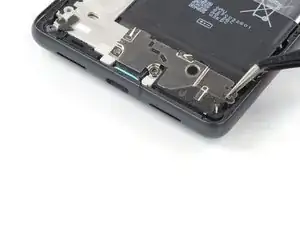
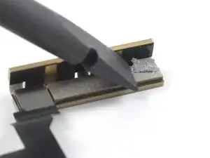
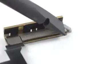
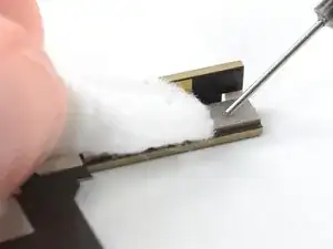
    • Use the flat end of a spudger to scrape the thermal paste off the mmWave antenna.

    • Clean any remaining thermal paste with isopropyl alcohol and either a coffee filter or a lint-free cloth.

    • Repeat the cleaning process for the thermal paste on the mmWave antenna bracket.

    • During reassembly, follow this guide for reapplying thermal paste onto the mmWave antenna.

  35. wCqaeeuGAUEWM2ff
    wCqaeeuGAUEWM2ff
    nI4T3GQWYkFd1OJC
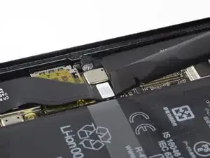
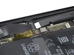
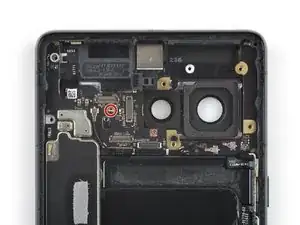
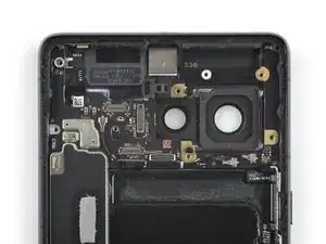
    • Use a spudger to disconnect the front facing camera cable by prying the connector straight up from its socket.

  36. DZLUle5gxQZTgsm3
    DZLUle5gxQZTgsm3
    HQIjNTxRWHppUAGW
    • Use a pair of tweezers to lift the front facing camera out of its recess and remove it.

  37. aorejAMQJCmvDXqY
    aorejAMQJCmvDXqY
    ANkVe2dvnMJGYhjI
    • Use a Torx T3 screwdriver to remove the 5.1 mm-long screw securing the rear cameras.

  38. v6lH5KBlVcOjBfuA
    v6lH5KBlVcOjBfuA
    ACaVIuR5VBmq2DAq
    • Use a spudger to disconnect the wide-angle camera cable by prying the connector straight up from its socket.

  39. NKxJShDNOvFXimBS
    NKxJShDNOvFXimBS
    ep6wNPMClcJUG3cw
    • Use a pair of tweezers to remove the wide-angle camera.

  40. lf4SxOaKeotwCgYE
    lf4SxOaKeotwCgYE
    sBZgE4rBpC5IuoVW
    • Use a spudger to disconnect the ultra wide-angle camera cable by prying the connector straight up from its socket.

  41. yymX1dnprKyxLdDG
    yymX1dnprKyxLdDG
    UBtFYQea4yEcApoQ
    • Use a pair of tweezers to remove the ultra wide-angle camera.

  42. 3vdBXCfKKAQYeiRV
    3vdBXCfKKAQYeiRV
    hEgRhOdYqWvw3WUw
    • Use a Torx T3 screwdriver to remove the 5.1 mm-long screw securing the earpiece speaker.

  43. L6CpMGXMWAC3QHQK
    L6CpMGXMWAC3QHQK
    bsmj5HS6XPVHOGhW
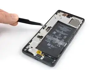
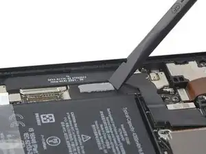
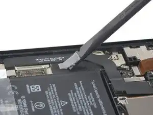
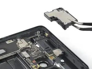
    • Insert the pointed end of a spudger underneath the bottom edge of the earpiece speaker.

    • Pry upwards to loosen the earpiece speaker.

  44. hgMFOM5UDSXBGaBf
    hgMFOM5UDSXBGaBf
    BPIrtvvXYYw6QL2c
    • Use a pair of tweezers to remove the earpiece speaker.

  45. GFuo5bPOYQeZb1cd
    GFuo5bPOYQeZb1cd
    USOY5ECjbK2puLXE
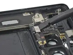
    • Use a spudger to disconnect the microphone interconnect cable by prying the connector straight up from its socket.

  46. oCD1kDlTbMDHRmrA
    oCD1kDlTbMDHRmrA
    SwiECJYVDJnwWukR
    ThXCpwTPfMx4DOYB
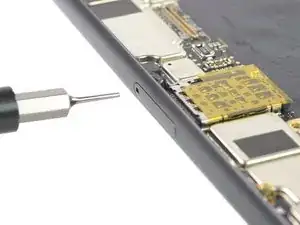
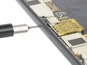
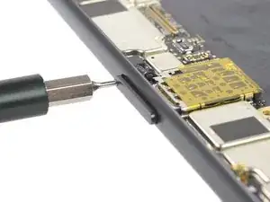
    • Insert a SIM eject tool, bit, or straightened paper clip into the SIM card tray hole.

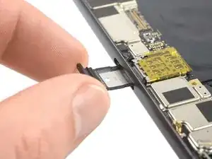
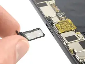
    • Press the SIM eject tool into the SIM card tray hole to eject the SIM card tray.

  47. HQrGfvsMwArFpLlZ
    HQrGfvsMwArFpLlZ
    gLIrJV4ax2ug5MmW
    • Remove the SIM card tray.

  48. yC3dGVCsJ4qGvXmp
    yC3dGVCsJ4qGvXmp
    36wPhfRwGZNqUNxm
    • Use a Torx T3 screwdriver to remove the 5.1 mm-long screw securing the motherboard.

  49. gQnQXBo6tcjoRdyY
    gQnQXBo6tcjoRdyY
    u636jMRAXCPcYgJb
    • Make sure the motherboard isn't blocked or tangled by any cables during this step.

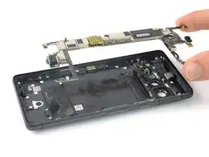
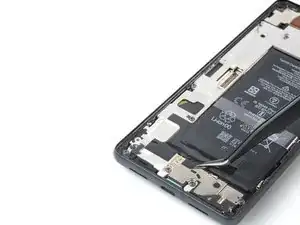
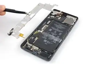
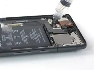
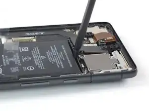
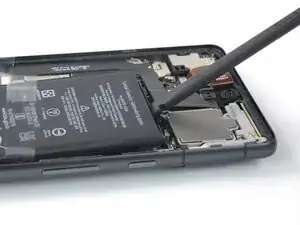
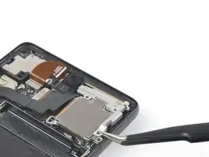
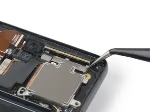
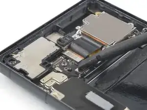
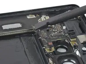
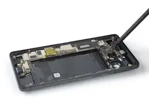
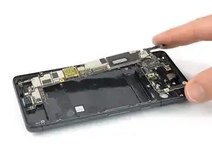
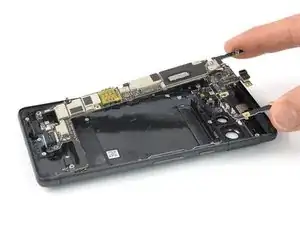
    • Insert a spudger underneath the top edge of the motherboard.

    • Pry upwards to loosen the motherboard until you can grab it with your fingers.

  50. iOlViAqErmaec46h
    iOlViAqErmaec46h
    KimyB12EKOq2nJMO
    IVu4gp2XfFkfMdZp
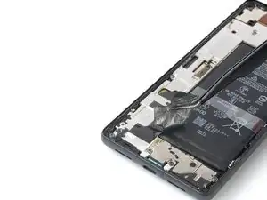
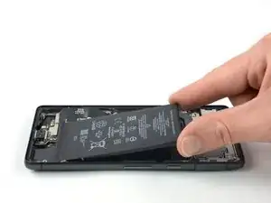
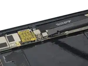
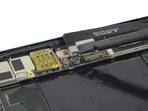
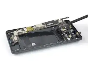
    • Grab the top end of the motherboard with your fingers.

    • Pull the motherboard in direction of the top edge of the frame to free the charging port from its recess.

    • Remove the motherboard.

    • Compare your new replacement part to the original part—you may need to transfer components like the antenna cables to your new motherboard.

Conclusion

To reassemble your device, follow these instructions in reverse order.

Repair didn’t go as planned? Try some basic troubleshooting, or ask our Google Pixel 7 answers community for help.

Dominik Schnabelrauch

Member since: 23/11/16

167396 Reputation

One comment

Hey, i am very glad to found your guide for Pixel 7 board replacement. And i have a question - i had my Pixel 7 died. Was at repair center, the tech said motherboard is just died . They have not this part . Please can you help me with finding of Pixel 7 board like a replacement part ? You can email me at vanko.68@gmail.com

Thanks in advance!

aidavanko -