Introduction

This is a prerequisite-only guide! This guide is part of another procedure and is not meant to be used alone.

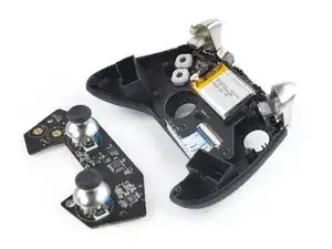
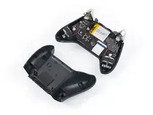
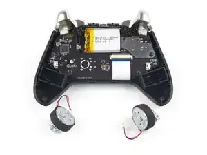
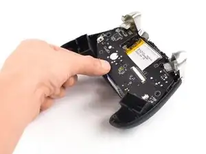
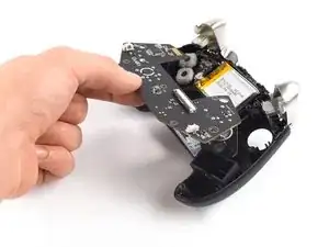
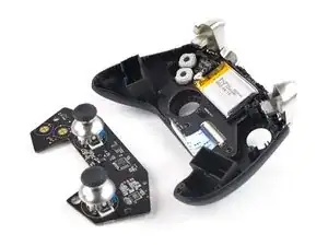
Use this guide to remove the mainboard assembly in your GuliKit KingKong 2 Pro.

  1. U4Nrl5tNANSaohOE
    • Use a Phillips #00 screwdriver to remove the four 11 mm-long screws securing the back cover.

    Hi, do you know what size screw is used for the outer portion? mine is stripped and i need to buy a new one

    Kevin Dimas -

    What you should use is a PH #0 Screwdriver, not a PH #00

    Yamatoklok -

  2. 4t5vaEkQAXGRo4hI
    4t5vaEkQAXGRo4hI
    6lUsZPPxiGFoWCey
    • The back cover of the GuliKit Kingkong 2 Pro is held in place by plastic clips.

    • Insert an opening pick into the gap between the front assembly and the back cover at the bottom edge of the controller.

    • Tilt your opening pick downwards to widen the gap.

  3. IvVFAaDOIQUiEHBJ
    IvVFAaDOIQUiEHBJ
    eIRQjRCoOywgKyLn
    • Insert an opening pick into the gap between the front assembly and the back cover at the outside of the right controller handle.

    • Slide the opening pick along the gap to separate the front assembly from the back cover.

  4. Qndkw5TYTOrOCZFu
    Qndkw5TYTOrOCZFu
    Sb6u11Dd5eWQFPxv
    • Insert an opening pick into the gap between the front assembly and the back cover at the outside of the left controller handle.

    • Slide the opening pick along the gap to separate the front assembly from the back cover.

  5. UWSlp65iZQ6OQH5C
    UWSlp65iZQ6OQH5C
    KWdSHPQ3GAyERcja
    • Separate the back cover from the front assembly and remove it.

  6. TciOVpng5G2RLV5d
    TciOVpng5G2RLV5d
    SxAwGaRR2ZFU3bbG
    FxSjGqHCO62TXIbJ
    • It's not mandatory to remove the two vibration motors to remove the mainboard assembly. However, other repairs become much easier with the motors removed. If you want to leave the motors in place, you can jump straight to step 9.

    • Pull on the connectors themselves and not the cables to avoid damaging them.

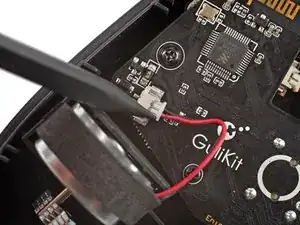
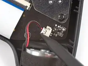
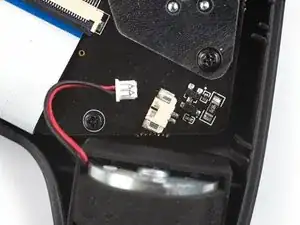
    • Use the point of a spudger to disconnect the right vibration motor by pushing the connector straight out of its socket.

    • If you can't disconnect the vibration motor with a spudger, use a pair of blunt nose tweezers to pull the connector out of its socket.

  7. aMHLoLTxSCAX1TOw
    aMHLoLTxSCAX1TOw
    FHNqdSAQnT4kpsMo
    ymLPUJYHM2pFTJYg
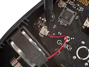
    • Use the point of a spudger to disconnect the left vibration motor by pushing the connector straight out of its socket.

  8. kfNV6jyFLDB5AJXY
    • Remove the vibration motors by lifting them out of the controller housing.

  9. yF6kX1SpxIbFlM5v
    yF6kX1SpxIbFlM5v
    KoNRLSHNBRbutkCL
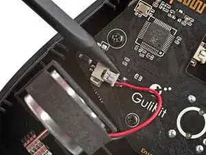
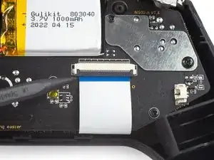
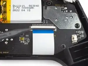
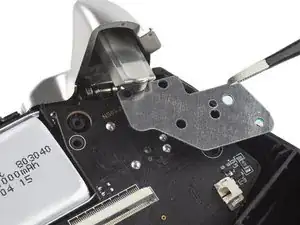
    • Use a spudger, an opening tool, or your fingernail to flip up the small, hinged locking flap on the interconnect cable's ZIF connector.

  10. dTXOkbZThCGYAuQO
    dTXOkbZThCGYAuQO
    EYPIQPII6HYFKRcy
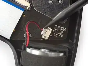
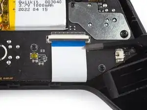
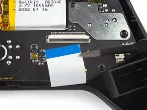
    • Use a pair of blunt nose tweezers to disconnect the interconnect cable by pulling the cable straight out of the connector.

  11. cpAOxRGJ5MRJUIif
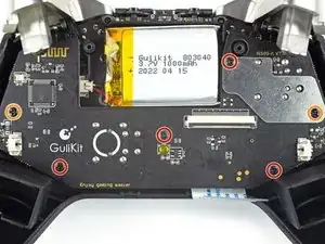
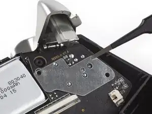
    • Use a Phillips #00 screwdriver to remove the screws securing the mainboard assembly:

    • Four 7.8 mm-long screws.

    • Two 11 mm-long screws.

  12. Z1EPXYJXEYt5V3o4
    Z1EPXYJXEYt5V3o4
    ZReMMIgEPAmIBKPH
    • Use a pair of blunt nose tweezers to remove the metal shield from the mainboard assembly.

  13. PgHHDOQ22cXUOh5g
    PgHHDOQ22cXUOh5g
    rACfkuWotWEoKllR
    b1GU2bsThlGub1jT
    • Remove the mainboard assembly by lifting it out of the controller housing.

    I highly recommend pulling off the joystick caps before removing this board, since the joysticky get caught on the other board. Alternatively, one can carefully slide back the mainboard, then unscrew and remove the triggers. Then the mainboard can be lifted up very easily. Accessing the trigger screws is a little tricky this way though.

    Sebastian Jost -

Conclusion

To reassemble your device, follow these instructions in reverse order.

Dominik Schnabelrauch

Member since: 23/11/16

167396 Reputation

0 comments