
Introduction
Follow this guide to replace the rubber conductive button pad and or exterior power and volume buttons.
The Switch uses JIS screws, but you can use a Phillips screwdriver in a pinch. Be very careful not to strip the screws. iFixit's Phillips bits are designed to be cross-compatible with JIS-style screws.
When reinstalling, attach the exterior plastic buttons to the rubber conductive pad and insert them together into the device.
Note: This guide, and the part we sell, are compatible with the original Nintendo Switch model released in 2017, as well as the newer refreshed model released in 2019 (model numbers HAC-001 and HAC-001(-01), respectively).
-
-
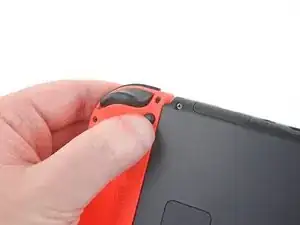
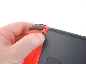
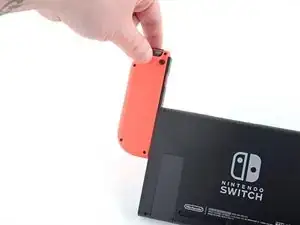
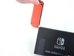
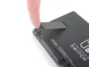
Press and hold down the small round button on the back of the Joy Con controller.
-
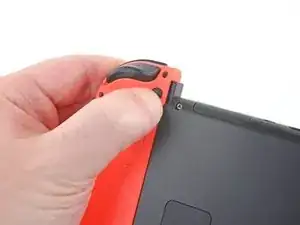
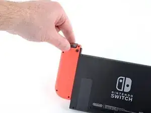
While you hold down the button, slide the controller upward.
-
-
-
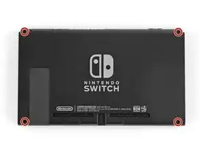
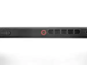
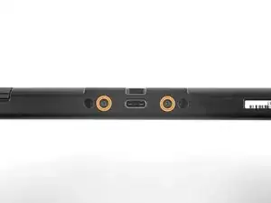
Use a JIS 000 driver or an official iFixit PH 000 driver to remove the following screws securing the rear panel:
-
One 2.5 mm-long screw on the top edge of the device
-
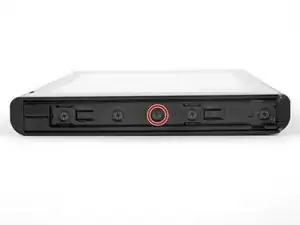
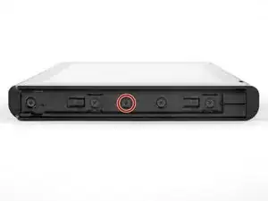
Two 2.5 mm-long screws on the bottom edge of the device
-
-
-
Use a JIS 000 screwdriver or an official iFixit PH 000 driver to remove the two 3.8 mm center screws on the sides of the device (one on each side).
-
-
-
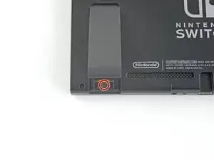
Use a JIS 000 screwdriver or an official iFixit PH 000 driver to remove the 1.6 mm screw in the kickstand well.
-
Close the kickstand.
-
-
-
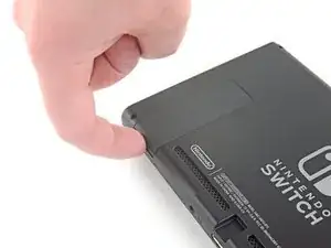
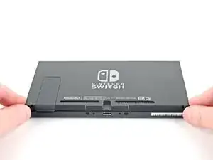
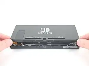
Open the game card cartridge flap.
-
Lift the rear panel up from the bottom of the device and remove it.
-
-
-
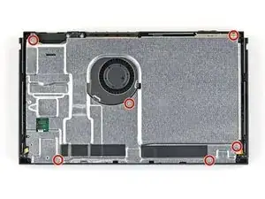
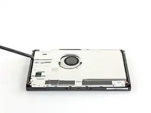
Use a JIS 000 screwdriver or an official iFixit PH 000 driver to remove the six 3 mm screws securing the shield plate to the device.
-
-
-
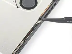
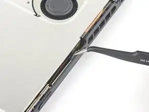
Use your fingers or a pair of tweezers to peel back the piece of foam on the top edge of the device near the fan exhaust port.
-
-
-
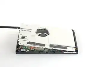
Insert a spudger underneath the shield plate along the edge of the device.
-
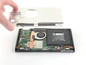
Pry up to lift the shield plate and remove it from the device.
-
You can reuse the pink thermal compound if you're careful. Keep the compound clean and make sure it makes solid contact between the heat sink and the shield during reassembly.
-
If you need to replace it, refer to our thermal paste guide to remove the old thermal compound and replace it with an appropriate compound, such as K5 Pro, during reassembly.
-
-
-
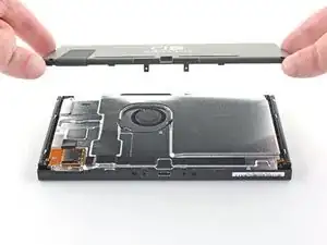
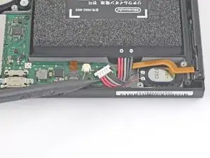
Use the point of a spudger to pry the battery connector straight up and out of its socket on the motherboard.
-
-
-
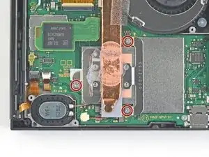
Use a JIS 000 screwdriver or an official iFixit PH 000 driver to remove the three 3 mm screws securing the heat sink to the motherboard.
-
-
-
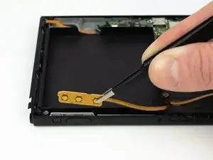
Carefully peel the two foam pieces stuck over both the heatsink and the fan away from the fan.
-
Insert the point of a spudger underneath the part of the foam that isn't stuck against anything,
-
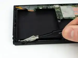
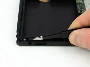
Press the top of the foam with your finger to hold it in place.
-
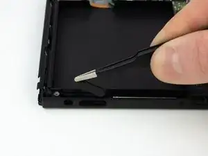
Roll the spudger tip underneath the foam all the way to the other end of the foam to release it.
-
-
-
Use a spudger or your fingers to lift the heatsink up and off the motherboard to remove it.
-
Apply thermal paste to all surfaces that had thermal paste applied previously. This includes between the heatpipe and aluminum shield, which the Switch uses as additional heatsinking.
-
-
-
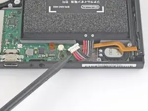
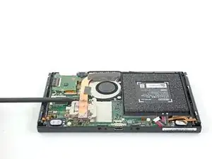
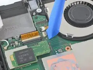
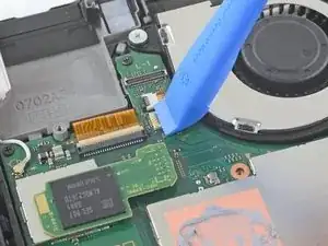
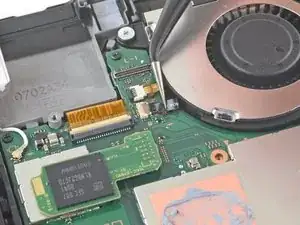
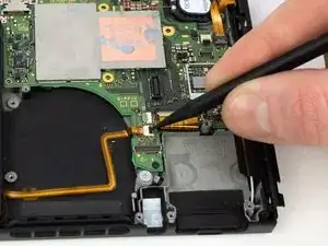
Use an opening tool, spudger, or your fingernail to flip up the small, hinged locking flap on the fan cable ZIF connector.
-
-
-
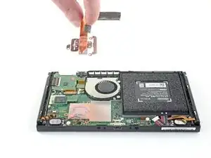
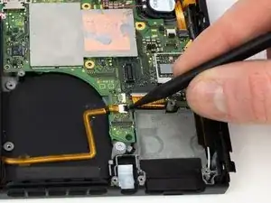
Use a pair of tweezers to pull the fan cable straight out of its connector on the motherboard.
-
-
-
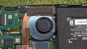
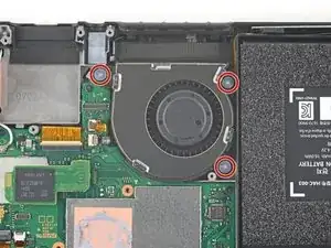
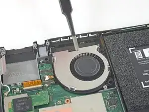
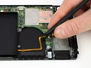
Use a JIS 000 screwdriver or an official iFixit PH 000 driver to remove the three 4.8 mm screws securing the fan.
-
-
-
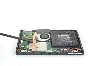
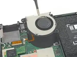
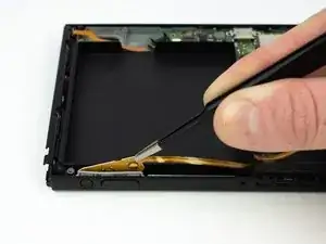
Use a pair of tweezers or your fingers to lift the fan straight up and remove it from the device.
-

To reassemble your device, follow these instructions in reverse order.

3 comments
What happens if the small black locking flap breaks?
Two angles are congruent if they have the same measure. You already know that when two lines intersect the vertical angles formed are congruent. You have also seen that if ∠A and ∠B are each complementary to ∠C, then ∠A ~= ∠B. There are other angle relationships to explore. When you expose these angle relationships, you will establish their truth using a formal proof.
Qui Ma -
This guide is missing the steps to Remove the microSD card reader and the steps to Remove the headphone jack and game card reader