Introduction
Follow this guide to replace a cracked or damaged digitizer on the Nintendo Switch Lite. This repair does not require removing the joysticks or buttons, but it makes the repair much easier.
The Switch Lite uses JIS screws, but you can use a Phillips screwdriver in a pinch. Be very careful not to strip the screws. iFixit's Phillips bits are designed to be cross-compatible with JIS-style screws.
Note: This guide is for the digitizer only. If the LCD stopped working, you may just need to replace it, rather than the digitizer. If you are replacing the screen (the LCD attached to the digitizer) follow this guide.
Note: This procedure requires removing the shield plate and heat sink. The thermal paste will need to be cleaned off of both components—as well as the CPU—and reapplied before reinstalling the shield plate and heat sink.
-
-
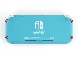
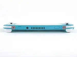
Use a JIS 000 driver or an official iFixit PH 000 driver to remove the following screws securing the back panel:
-
Two 3.6 mm-long screws on the top of the device
-
Two 3.6 mm-long screws on the bottom of the device
-
-
-
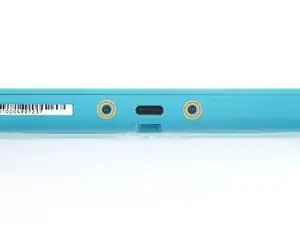
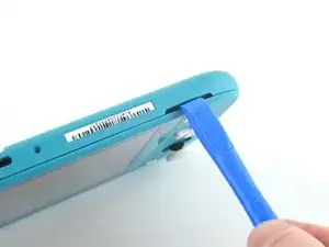
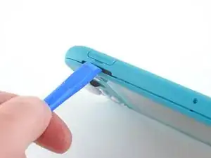
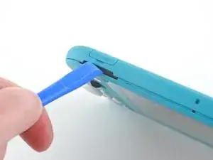
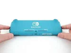
Insert an opening tool into the left speaker grille on the bottom of the device.
-
Twist the opening tool to release the clips securing the back panel.
-
-
-
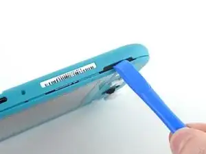
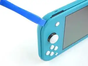
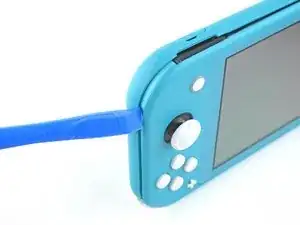
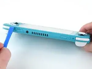
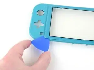
Slide the opening tool around the bottom-left corner to release the clips on the left side of the device.
-
-
-
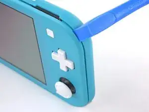
Insert an opening tool into the right speaker grille on the bottom of the device.
-
Twist the opening tool to release the clips.
-
-
-
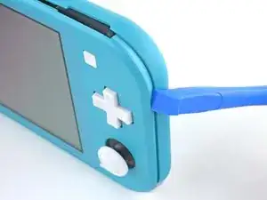
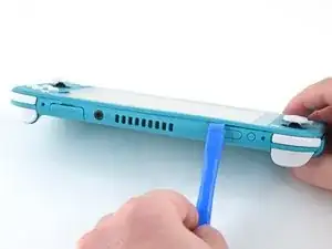
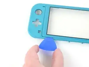
Slide and pry the opening tool around the bottom-right corner to release the clips on the right side of the device.
-
-
-
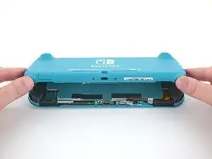
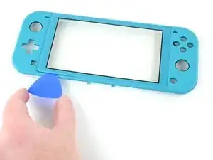
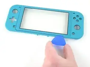
Continue sliding and prying the opening tool along the gap on the top of the device to release the clips.
-
-
-
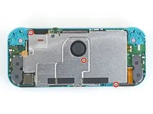
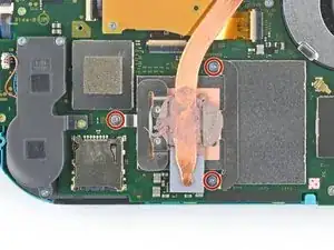
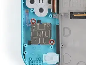
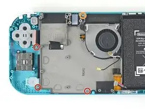
Use a JIS 000 driver or an official iFixit PH 000 driver to remove the following four screws:
-
Three 3.1 mm screws
-
One 4.5 mm screw
-
-
-
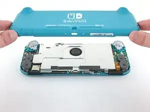
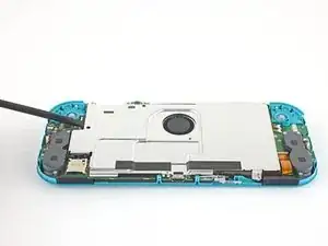
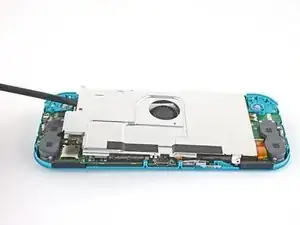
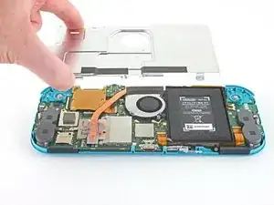
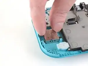
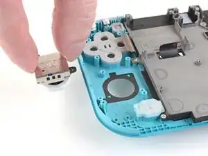
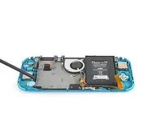
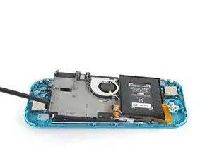
Use a spudger or your fingers to lift the shield plate up and out of the device.
-
Remove the shield plate.
-
-
-
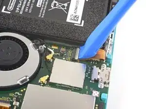
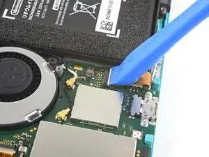
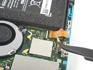
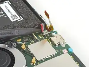
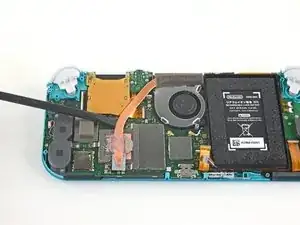
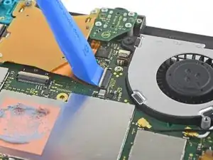
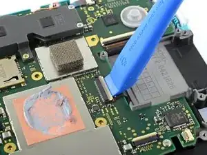
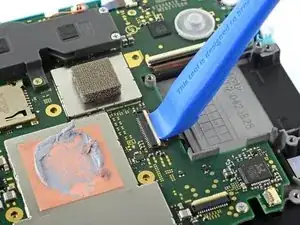
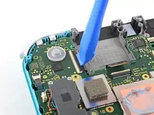
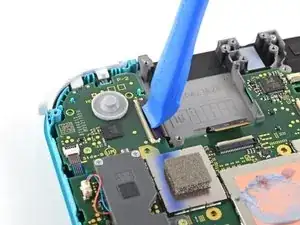
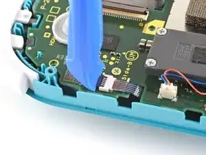
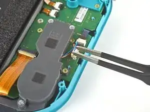
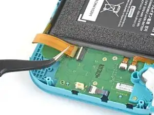
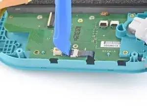
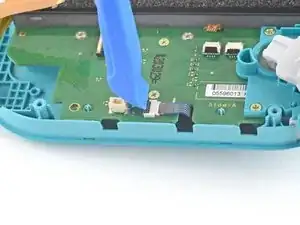
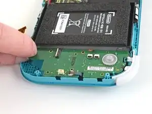
Use an opening tool or your fingernail to flip up the small, hinged locking flap on the motherboard interconnect cable's ZIF connector.
-
-
-
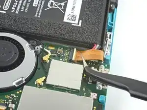
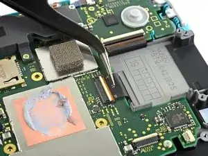
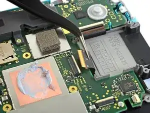
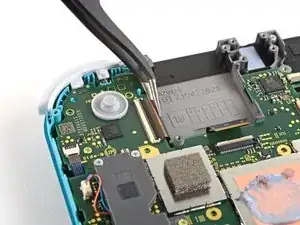
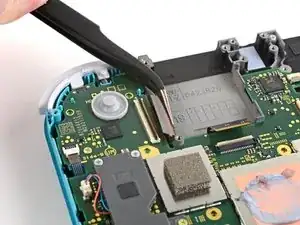
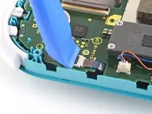
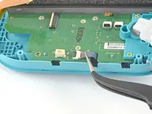
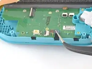
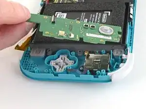
Use a pair of tweezers to slide the interconnect cable out of its connector on the motherboard.
-
-
-
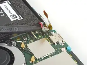
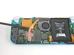
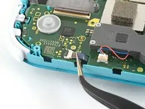
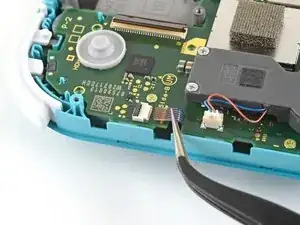
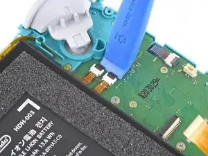
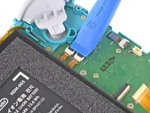
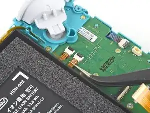
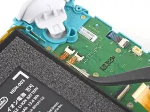
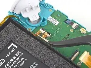
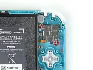
Use the point of a spudger to pry the battery connector straight up and out of its socket on the motherboard.
-
-
-
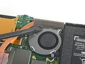
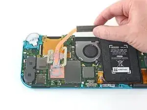
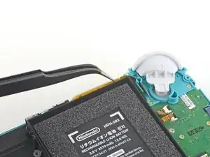
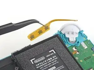
Use the flat end of a spudger or your fingers to carefully peel up the foam that's lightly adhered to the fan.
-
-
-
Use a JIS 000 driver or an official iFixit PH 000 driver to remove the three 3 mm screws securing the heat sink to the motherboard.
-
-
-
Use a spudger or your fingers to lift the heatsink up and off of the motherboard to remove it.
-
-
-
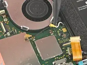
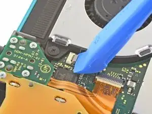
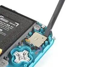
Use an opening tool or your fingernail to flip up the small, hinged locking flap on the game card reader cable's ZIF connector.
-
-
-
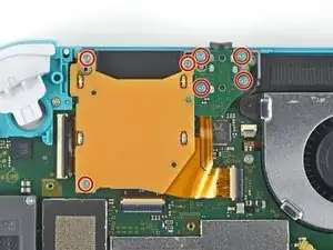
Use a JIS 000 driver or an official iFixit PH 000 driver to remove the seven 3.1 mm screws securing the game card reader and headphone jack.
-
-
-
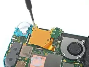
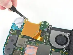
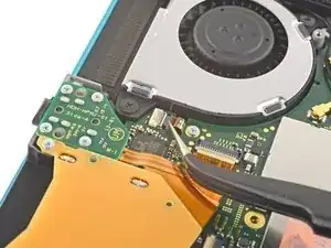
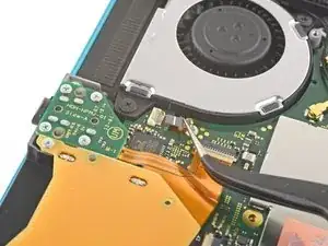
Use a pair of tweezers or your fingers to carefully lift the game card reader and maneuver it to the left to slide the cable out of its connector.
-
Remove the game card reader and headphone jack.
-
-
-
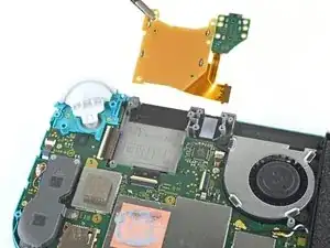
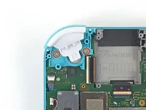
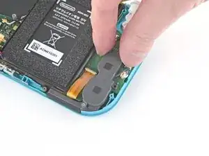
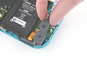
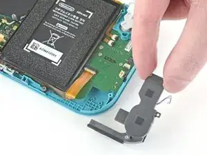
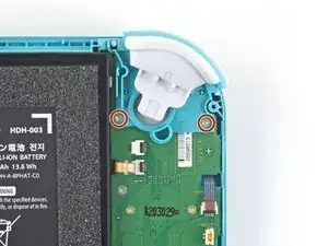
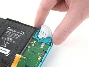
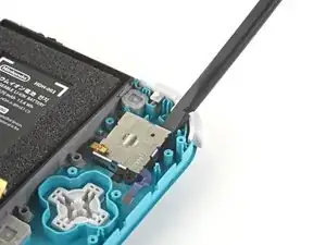
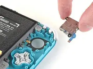
Use a JIS 000 driver or an official iFixit PH 000 driver to remove the two 4.5 mm screws securing the right trigger button assembly to the motherboard.
-
-
-
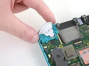
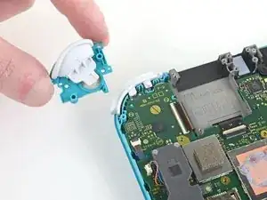
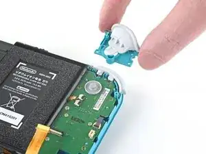
Use a pair of tweezers or your fingers to remove the right trigger button assembly's rubber pad if it didn't stay attached to the button assembly.
-
-
-
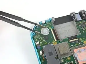
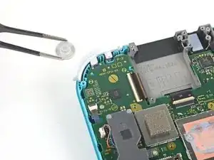
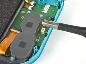
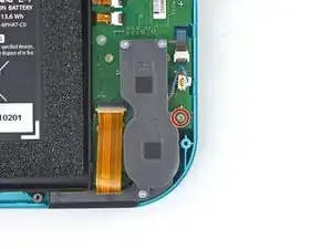
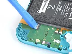
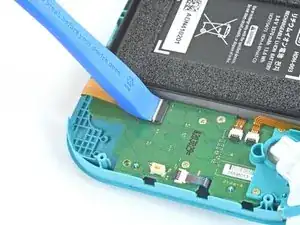
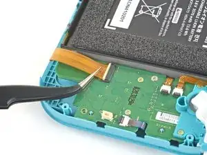
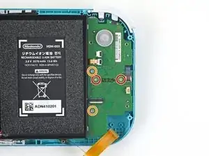
Use the point of a spudger to pry the black antenna cable straight up out of its socket on the motherboard.
-
Repeat the same process for the white antenna cable.
-
-
-
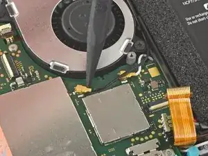
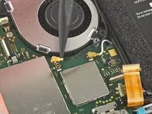
Use an opening tool or your fingernail to flip up the small, hinged locking flap on the fan cable's ZIF connector.
-
-
-
Use an opening tool or your fingernail to flip up the small, hinged locking flap on the screen cable's ZIF connector.
-
-
-
Use an opening tool or your fingernail to flip up the small, hinged locking flap on the digitizer cable's ZIF connector.
-
-
-
Use a pair of tweezers to slide the digitizer cable out of its connector on the motherboard.
-
-
-
Use an opening tool or your fingernail to flip up the small, hinged locking flap on the right joystick cable's ZIF connector.
-
-
-
Use a pair of tweezers to slide the right joystick cable out of its connector on the motherboard.
-
-
-
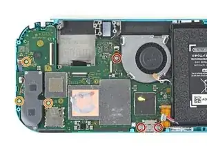
Use a JIS 000 driver or an official iFixit PH 000 driver to remove the following six screws securing the motherboard:
-
Three 3.1 mm screws
-
Three 4.5 mm screws
-
-
-
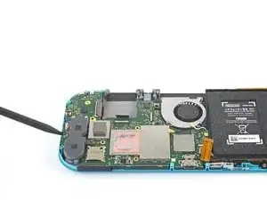
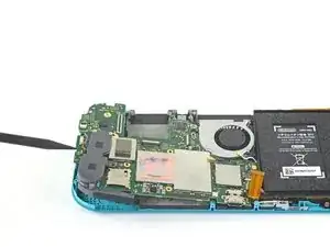
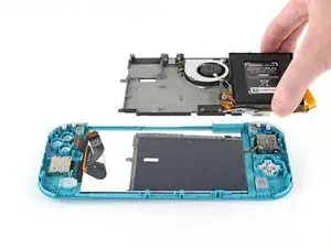
Insert a spudger in the gap between the frame and the motherboard and lift the motherboard up and out of its recess.
-
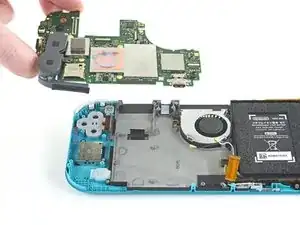
Remove the motherboard assembly.
-
-
-
Use a JIS 000 driver or an official iFixit PH 000 driver to remove the two 3.5 mm screws securing the joystick.
-
-
-
Use a pair of tweezers or your fingers to pull the left speaker cable straight up and out of its socket on the daughterboard.
-
-
-
Use a JIS 000 driver or an official iFixit PH 000 driver to remove the 4.5 mm screw securing the left speaker module.
-
-
-
Use an opening tool or your fingernail to flip up the small, hinged locking flap on the motherboard interconnect cable's ZIF connector.
-
-
-
Use a pair of tweezers to slide the motherboard interconnect cable out of its connector on the daughterboard.
-
-
-
Use an opening tool or your fingernail to flip up the small, hinged locking flaps on the two ribbon cable ZIF connectors.
-
-
-
Use a pair of tweezers to slide the daughterboard screen cable out of its connector on the motherboard.
-
Repeat this procedure for the volume buttons cable.
-
-
-
Use an opening tool or your fingernail to flip up the small, hinged locking flap on the left joystick cable's ZIF connector.
-
-
-
Use a pair of tweezers to slide the left joystick cable out of its connector on the daughterboard.
-
-
-
Use a JIS 000 driver or an official iFixit PH 000 driver to remove the two 4.5 mm screws securing the left trigger button assembly.
-
-
-
Use a JIS 000 driver or an official iFixit PH 000 driver to remove the following four screws:
-
Two 4.5 mm screws
-
Two 6 mm screws
-
-
-
Use a JIS 000 driver or an official iFixit PH 000 driver to remove the two 3.5 mm screws securing the left joystick.
-
-
-
Use the flat end of a spudger to lift the joystick up and out of its recess.
-
Use your fingers to remove the joystick.
-
-
-
Use a JIS 000 driver or an official iFixit PH 000 driver to remove the following four screws:
-
Three 2.5 mm screws
-
One 6 mm screw
-
-
-
Use a spudger or your fingers to lift the midframe assembly up and out of its recess.
-
Remove the midframe assembly.
-
-
-
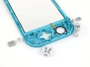
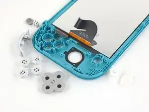
At this point in the repair, remove all of the buttons if you haven't done so already, to prevent them from falling out and getting lost.
-
-
-
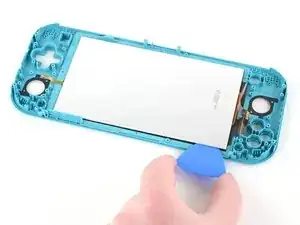
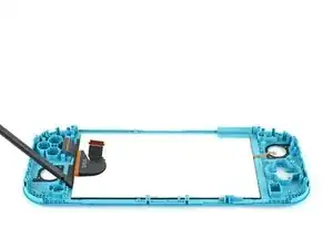
Insert an opening pick between the frame and the top edge of the LCD to begin separating the two components.
-
-
-
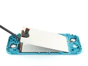
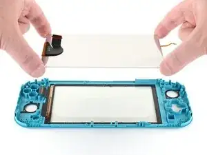
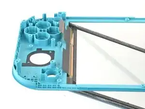
Use the flat end of a spudger or your fingers to lift the LCD up and out of the frame to remove it.
-
-
-
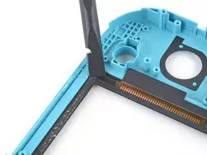
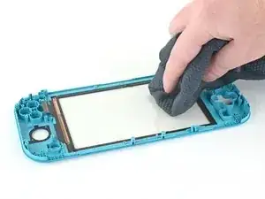
Use the flat end of a spudger to scrape off the remaining adhesive around the perimeter of the digitizer.
-
-
-
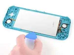
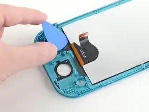
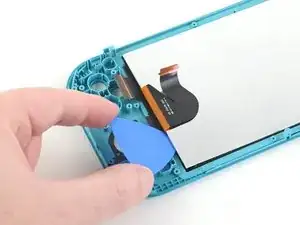
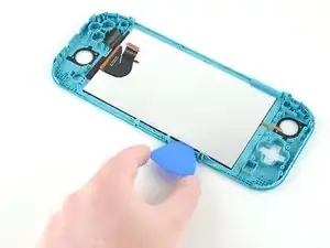
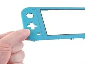
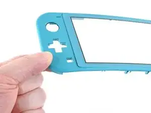
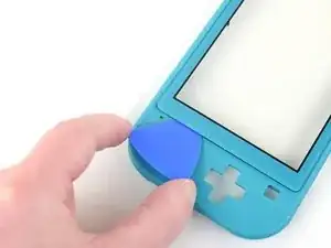
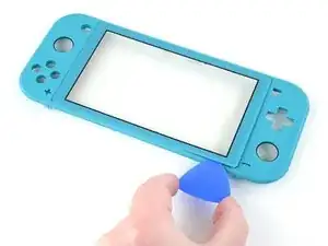
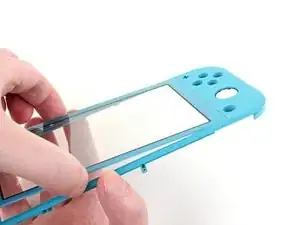
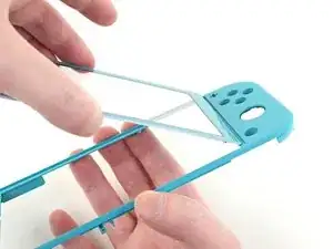
Slightly bend the left side of the frame to create a gap between the digitizer and the frame.
-
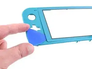
Insert an opening pick into the gap.
-
-
-
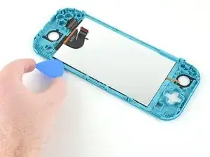
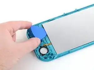
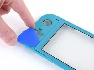
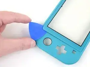
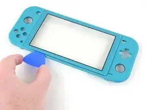
Continue working the opening pick around the top-left edge of the digitizer to slice the adhesive.
-
-
-
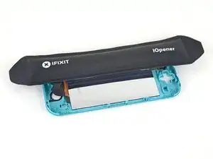
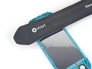
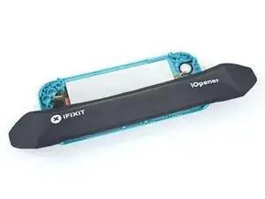
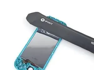
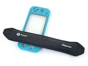
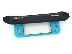
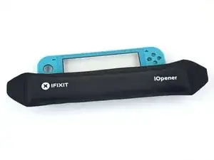
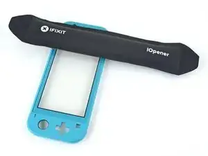
Apply a heated iOpener to the front side of the digitizer along the bottom edge for 2 minutes.
-
-
-
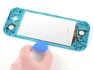
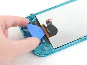
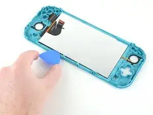
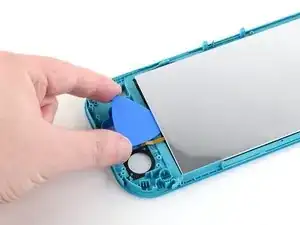
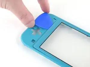
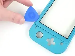
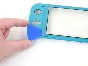
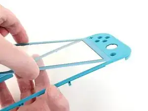
Continue working the opening pick around the bottom-left edge of the digitizer to slice the adhesive.
-
-
-
Apply a heated iOpener to the front side of the digitizer along the right edge for 2 minutes.
-
-
-
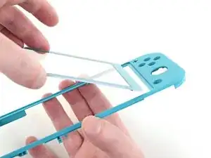
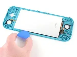
Lift the right side of the digitizer straight off the frame at a 45-degree angle to remove it.
-


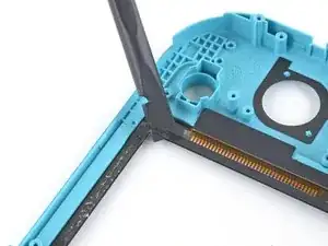

To reassemble your device, follow these instructions in reverse order.
Take your e-waste to an R2 or e-Stewards certified recycler.
Repair didn’t go as planned? Try some basic troubleshooting, or ask our Nintendo Switch Lite Answers community for help.

4 comments
Great guide, but quick tip when removing the screen. There are two pieces of the screen sandwiched together and when I took mine apart, these two pieces came unstuck and ruined the screen itself. The digitizer was fine, but the LCD came apart. So make sure the opening pick gets under both of these parts rather than just the reflective back.
I bought this Switch Lite with a broken LCD to repair and sell, so the screen was already blown out, but I had the same issue. The LCD was still connected to the digitizer and it actually peeled the LCD apart. As I said earlier, the LCD was already broke so it wasn’t a big issue, but I would of been fairly angry if it hadn’t of been.
it looks like it might be possible to do steps 1 - 10, then step 28, then steps 66 onwards, and reverse to reassemble, the guide isn’t clear why it would be required to do a full tear down, is there something that would make this method not work or more likely to cause further damage, if I’m just switching out the digitizer, pun intended.. :) ?
Were I to guess, I would say that the full teardown guide is meant to apply to any, and all, scenarios, regardless of any unmentioned issues that a user may have.
Another possibility is that if a user has a damaged digitizer from a drop, or other type of impact(s); then by performing a full teardown, they may discover other elements in need of repair.
All my screws got stripped any ideas on how to remove?
Almost A Mammal -
A Y0 screwdriver seemed to work better for me.
Tommy Morrill -
What type of screw driver do I use to un screw the screws and which way
Luca Capito -