Introduction
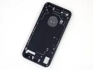
Use this guide to remove all components from the rear case of your iPhone 7. This guide will show you how to remove speaker vents, button cables, and button covers so you can replace a dented or bent cover.
Tools
Parts
-
-
Power off your iPhone before beginning disassembly.
-
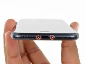
Remove the two 3.4 mm pentalobe screws on the bottom edge of the iPhone.
-
-
-
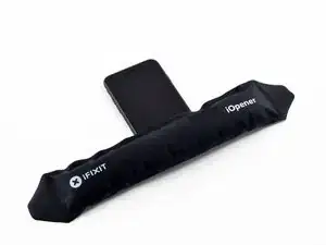
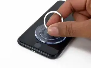
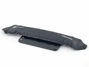
Use a hairdryer or prepare an iOpener and apply it to the lower edge of the iPhone for about a minute in order to soften up the adhesive underneath.
-
-
-
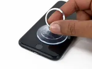
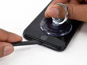
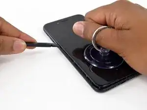
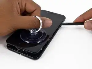
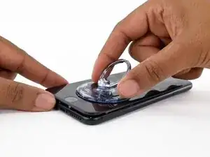
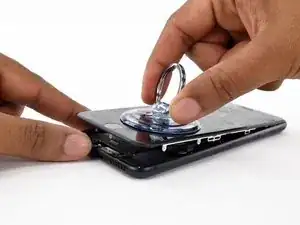
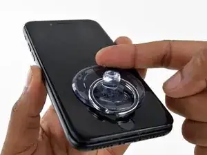
Pull up on the suction cup to create a small gap between the display assembly and the rear case.
-
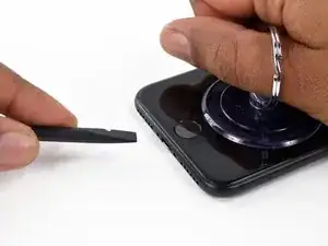
Insert the flat end of a spudger into the gap.
-
-
-
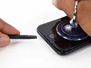
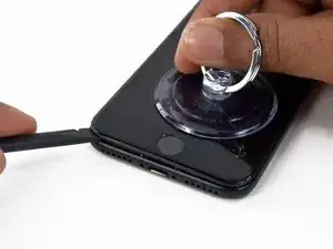
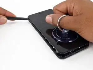
Slide the spudger to the left along the lower edge of the iPhone.
-
Twist the spudger to widen the gap between the display and rear case.
-
-
-
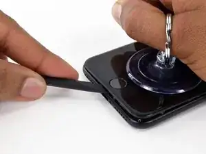
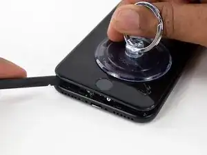
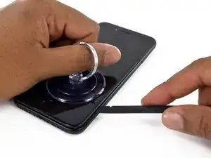
Slide the spudger up the left side of the iPhone, starting at the lower edge and moving towards the volume control buttons and silent switch.
-
-
-
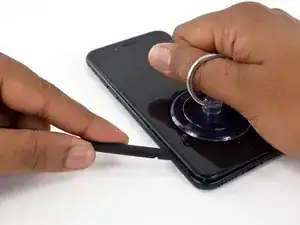
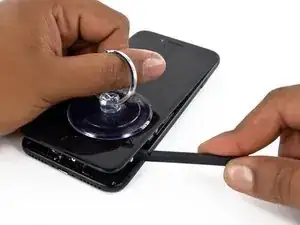
Insert the flat edge of a spudger into the bottom right corner of the device.
-
Twist the spudger to widen the gap between the display assembly and the rear case.
-
Slide the flat end of the spudger up the right side of the phone to break up the adhesive holding the display in place.
-
-
-
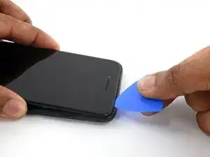
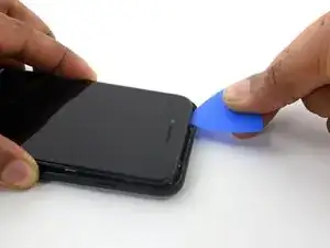
Slide an opening pick along the top edge of the iPhone, between the rear case and front panel, to break up the remaining adhesive holding the screen in place.
-
-
-
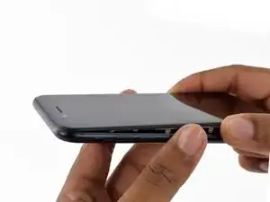
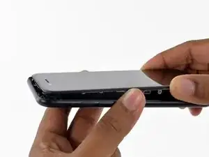
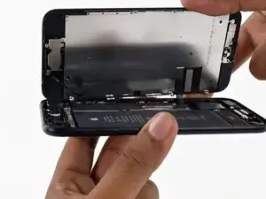
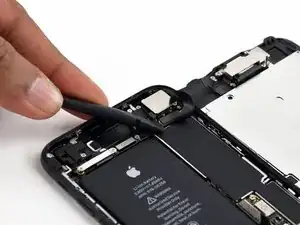
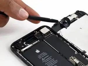
Pull the display assembly slightly away from the top edge of the phone to disengage the clips holding it to the rear case.
-
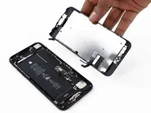
Open the iPhone by swinging the display up from the left side, like the back cover of a book.
-
-
-
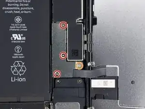
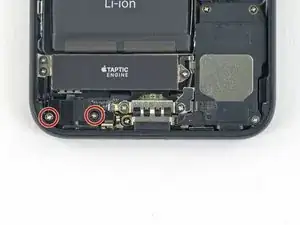
Remove four tri-point Y000 screws securing the lower connector bracket, of the following lengths:
-
Three 1.2 mm screws
-
One 2.4 mm screw
-
-
-
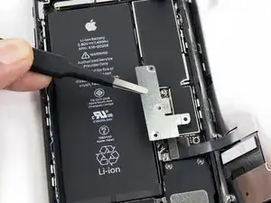
Use the point of a spudger to lift the battery connector out of its socket on the logic board.
-
-
-
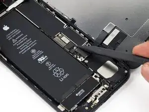
Use a spudger or a fingernail to disconnect the two lower display connectors by prying them straight up from their sockets on the logic board.
-
-
-
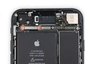
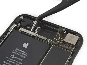
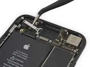
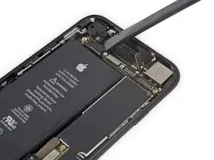
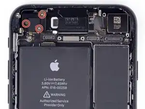
Remove the two 1.3 mm Phillips #000 screws securing the bracket over the front panel sensor assembly connector.
-
-
-
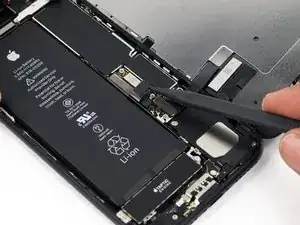
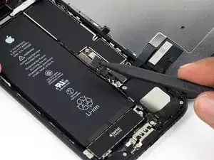
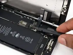
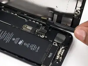
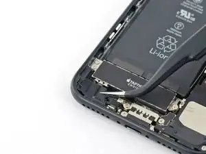
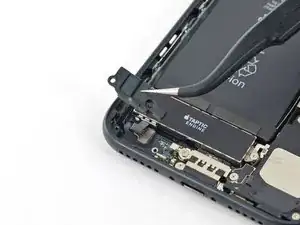
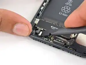
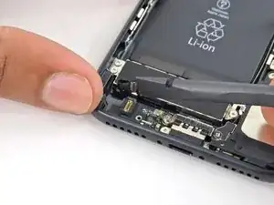
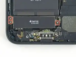
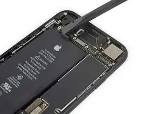
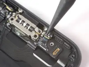
Use the flat end of a spudger to disconnect the Taptic Engine connector from its socket on the logic board.
-
-
-
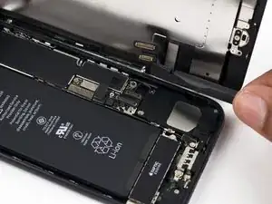
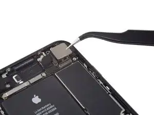
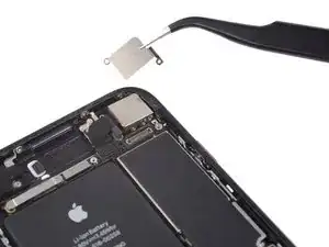
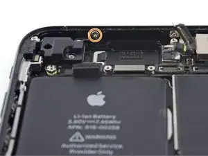
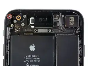
Remove the Phillips screw securing the Wi-Fi diversity antenna to the rear case:
-
One 3.2 mm screw
-
-
-
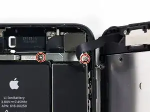
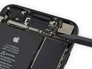
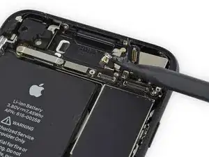
Remove the following three Phillips screws securing the speaker to the rear case:
-
Two 1.3 mm screws
-
One 2.0 mm screw
-
-
-
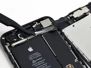
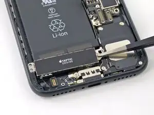
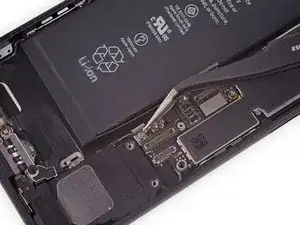
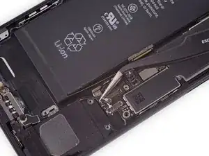
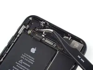
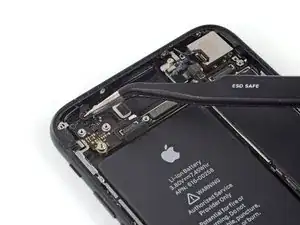
Use the point of a spudger to lift the two antenna cable connectors up off of the sockets on the logic board.
-
-
-
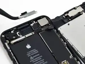
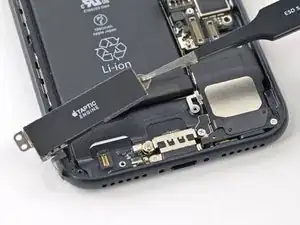
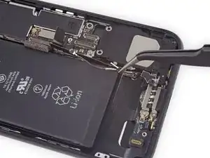
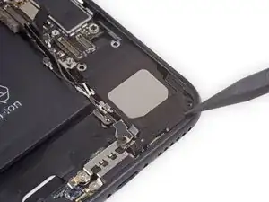
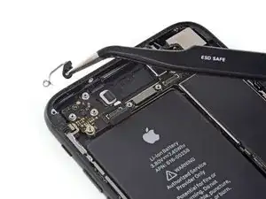
Use the tip of a spudger to slide the speaker assembly towards the logic board and off of the rear case.
-
-
-
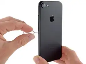
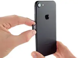
Insert a SIM card eject tool or a paperclip into the small hole in the SIM card tray.
-
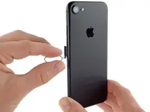
Press to eject the tray.
-
Remove the SIM card tray assembly from the iPhone.
-
-
-
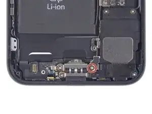
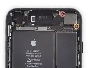
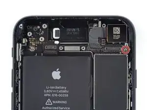
Remove the following Phillips screws securing the rear camera bracket to the rear case:
-
One 1.3 mm screw
-
One 2.5 mm screw
-
-
-
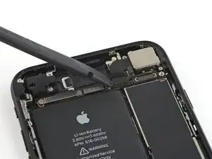
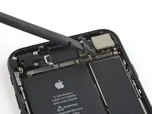
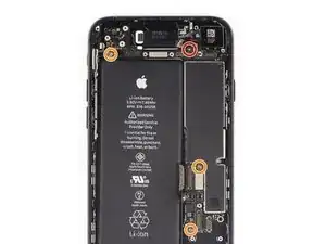
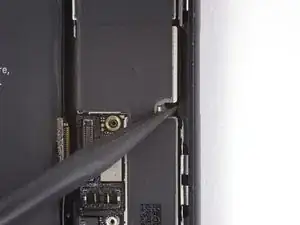
Use the pointed end of a spudger to pry up and disconnect the antenna bus connector, just left of the rear camera module.
-
-
-
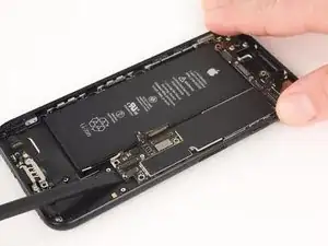
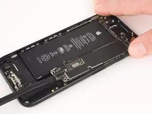
Remove the four Phillips screws securing the Wi-Fi antenna:
-
Three 1.2 mm screws
-
One 1.7 mm screw
-
-
-
Remove the following screws:
-
One 1.4 mm Phillips screw
-
Three 2.2 mm standoff screws
-
In a pinch, a small flathead screwdriver will do the job—but use extra caution to ensure it doesn't slip and damage surrounding components.
-
-
-
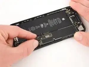
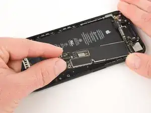
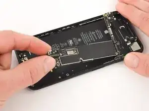
Use the flat end of a spudger to gently lift the battery connector end of the logic board up.
-
-
-
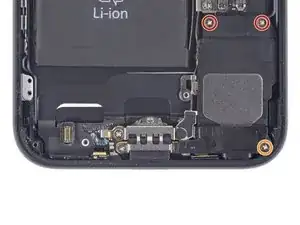
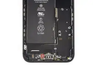
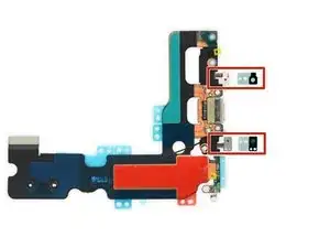
Remove the two stickers covering the screws that secure the lightning connector to the bottom of the rear case.
-
-
-
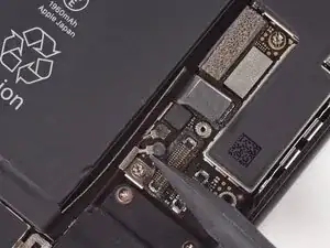
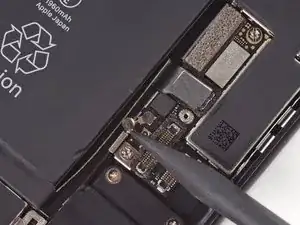
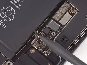
Use the pointed end of a spudger to separate the two microphones from the bottom of the rear case.
-
-
-
Use a hairdryer or reheat your iOpener to heat the lower edge of the phone.
-
Wait for about a minute, allowing the adhesive to warm up before proceeding to the next step.
-
-
-
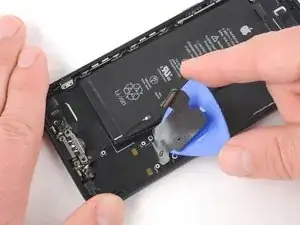
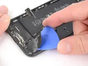
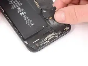
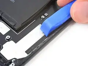
Starting from the middle of the phone, slide an opening pick underneath the lightning connector to separate it from the rear case.
-
-
-
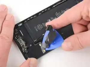
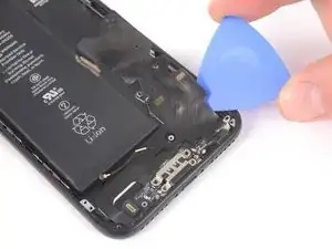
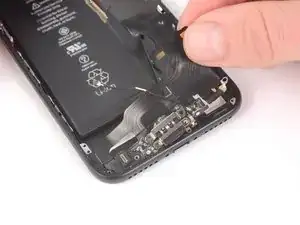
Continue to slide the pick towards the lightning connector to further separate the assembly from the rear case.
-
-
-
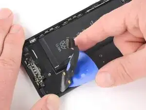
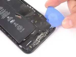
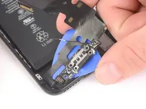
Continue to slide the pick underneath the lightning connecter assembly.
-
Stop sliding the pick once it passes the battery.
-
-
-
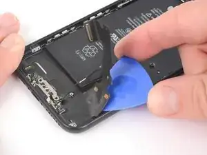
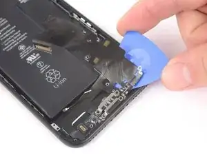
Starting at the corner of the phone, slide the pick underneath the assembly towards the lightning connector.
-
Stop sliding the pick when it reaches the lightning connector.
-
-
-
Slide a pick below the lightning connector to further separate the lightning connector assembly from the rear case.
-
Continue to slide the pick until the lightning connector assembly is no longer adhered to the rear case.
-
-
-
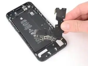
Remove the lightning connector assembly.
-
Use a plastic tool to scour any bits of adhesive residue from the rear case.
-
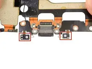
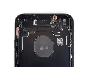
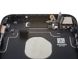
Make sure the Lightning connector assembly is correctly positioned so that the two white dots on the iPhone's rear case show through the two circular cutouts in the Lightning flex cable. If they don't, the flex cable will remain misaligned and you won't be able to reconnect it to its socket on the logic board.
-
-
-
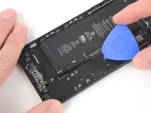
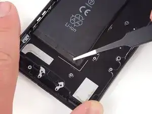
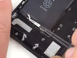
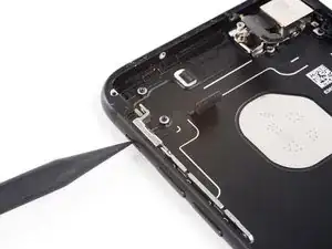
Use a pair of tweezers with blunt tips to peel back one of the adhesive strips on the lower edge of the battery.
-
-
-
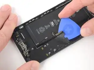
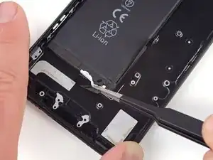
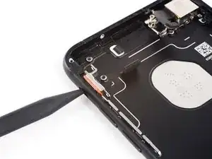
Use a pair of tweezers with blunt tips to peel back the other adhesive strip on the lower edge of the battery.
-
-
-
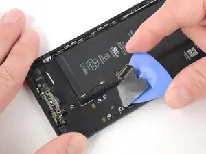
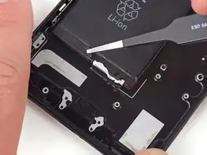
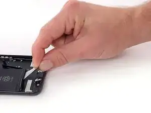
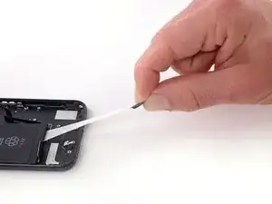
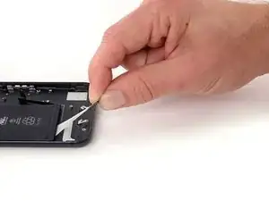
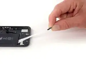
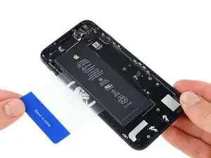
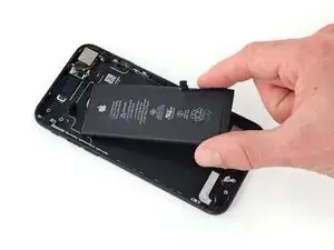
Slowly pull one battery adhesive tab away from the battery, toward the bottom of the iPhone.
-
Pull steadily, maintaining constant tension on the strip until it slips out from between the battery and the rear case. For best results, pull the strip at a 60º angle or less.
-
-
-
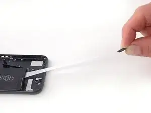
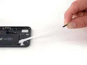
Repeat the previous step for the second strip.
-
If you removed both adhesive strips successfully, skip the next step.
-
Otherwise, if either of the adhesive strips broke off underneath the battery and could not be retrieved, continue with the next step below.
-
-
-
Prepare an iOpener and apply it to the back of the rear case, directly over the battery. Alternatively, you can apply heat using a heat gun or hair dryer.
-
After about a minute, remove the iOpener, flip the phone over and use a plastic card to break up any remaining adhesive behind the battery.
-
-
-
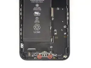
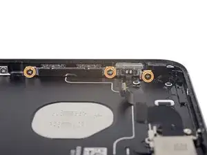
Remove the following Phillips screws:
-
Two 1.9 mm screws securing the power button.
-
Three 2.3 mm screws securing the volume buttons.
-
-
-
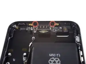
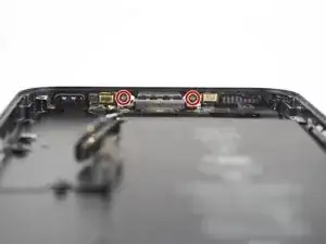
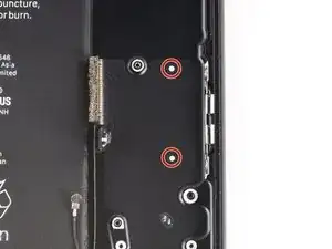
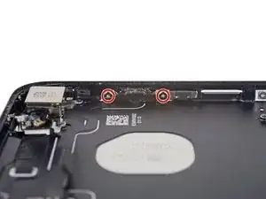
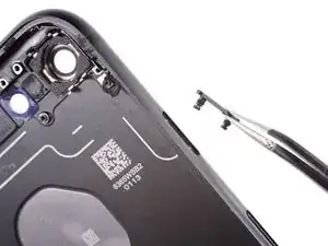
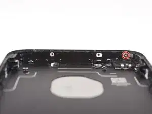
Remove the following 1.3 mm Phillips screws:
-
One screw beside the rear-facing camera
-
One screw on the rear case
-
-
-
From the outside of the phone, push the hold switch into the rear case with the point of a spudger.
-
This action will free the hold switch and gasket from the rear case.
-
-
-
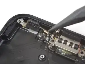
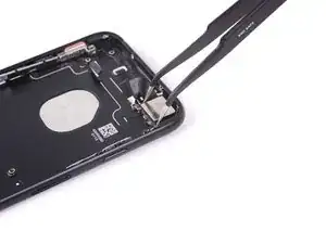
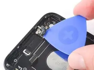
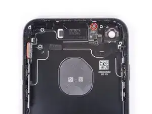
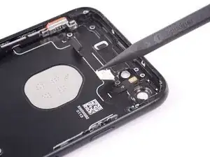
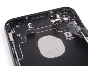
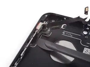
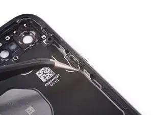
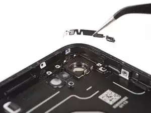
Moving from power button side of the phone, use an opening pick to separate the adhesive holding the antenna flex cable to the rear case.
-
-
-
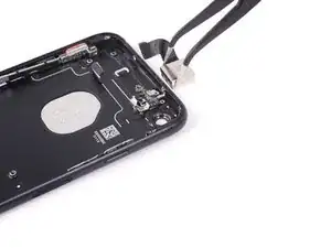
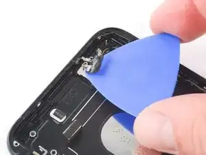
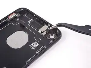
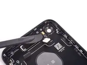
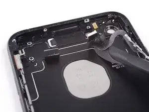
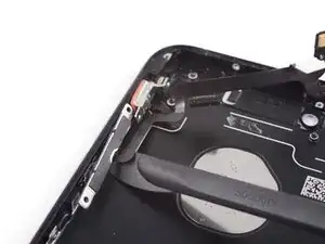
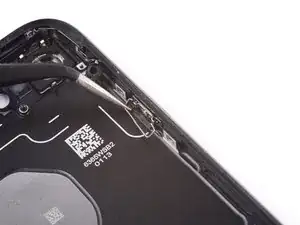
Slide the point of an opening pick underneath the antenna flex cable towards the top of the phone, separating the remaining adhesive.
-
-
-
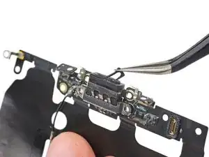
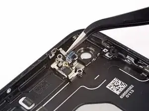
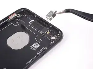
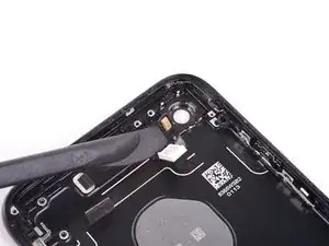
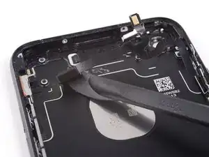
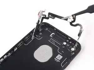
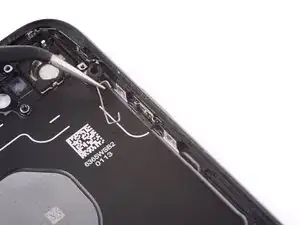
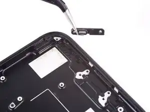
Use tweezers to move the antenna flex cable away from the edge of the phone, freeing the screw bracket from the rear case.
-
Remove the antenna flex cable.
-
-
-
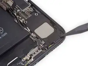
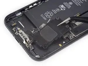
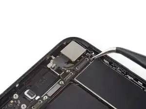
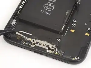
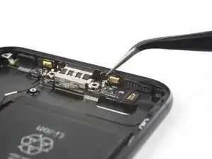
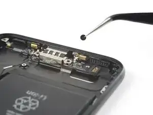
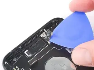
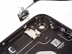
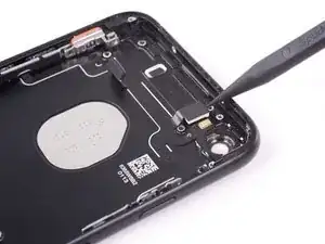
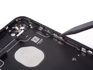
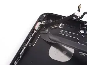
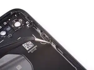
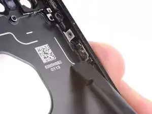
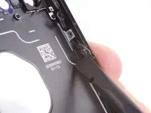
Use the blade of a Halberd spudger to separate the adhesive holding the microphone to the rear case.
-
-
-
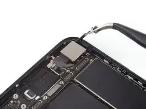
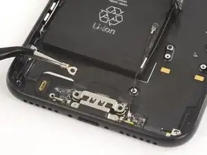
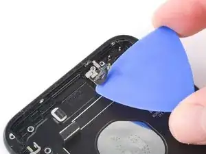
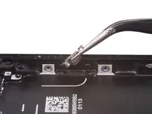
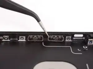
Slide the blade of a halberd spudger under the power button end of the button cable to separate it from the adhesive on the rear case.
-
Continue to separate the adhesive by moving the blade towards the top of the phone.
-
-
-
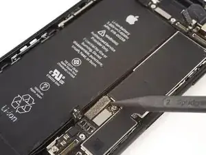
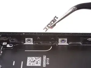
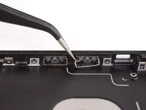
Continue to move the blade of the halberd spudger underneath the power and volume control cable.
-
-
-
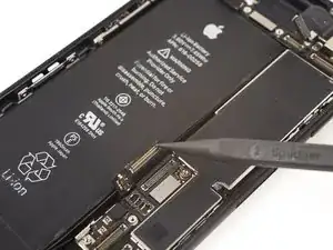
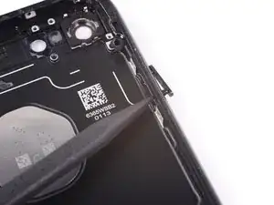
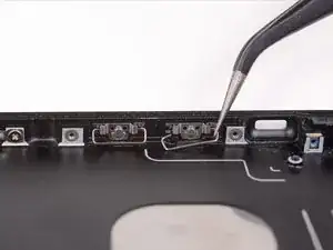
Slide the halberd spudger under the volume control portion of the button cable.
-
Gently slide the blade underneath the cable towards the bottom of the phone, separating the remaining adhesive.
-
-
-
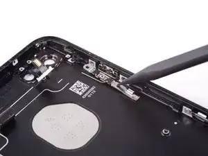
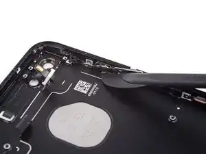
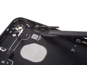
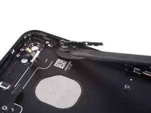
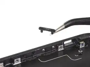
Use the pointed end of a spudger to push the power button cover out of the rear case.
-
Remove the power button cover.
-
-
-
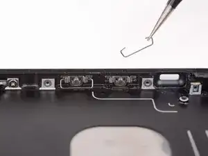
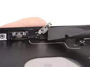
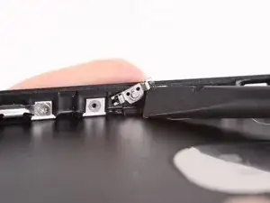
Pull the volume button clip towards the bottom of the phone to free it from the bracket.
-
Pull the clip towards the top of the phone to remove it.
-
-
-
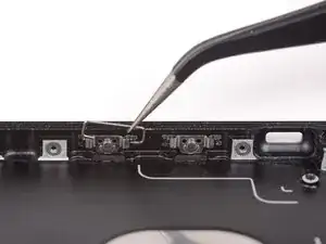
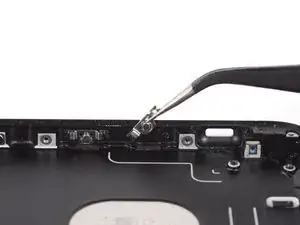
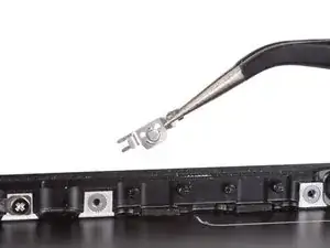
Slide the flat end of a spudger underneath the bottom edge of the volume button bracket.
-
Adjust the spudger so that it can move away from the rear case without contacting the protruding peg that is on the volume button.
-
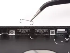
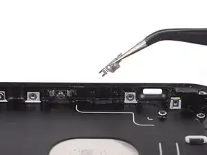
Rotate the spudger to pop the bracket off of the peg on the volume button.
-
-
-
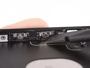
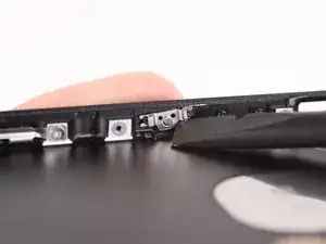
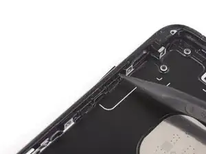
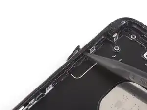
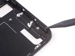
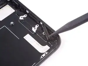
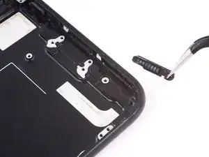
Use the pointed end of a spudger to push each of the volume button covers out of the rear case.
-
Remove the volume button covers.
-


To reassemble your device, follow these instructions in reverse order.

10 comments
Great manual. I was successful in this repair but bought a rear case with small parts. Safes up a lot of work and time :)
Dreetn -
Great Guide!
There are some components that may need to be transferred to your new case, which are not in this guide:
1 speaker screens
2 screen mounting catches
3 put the SIM card tray ejector pin back in BEFORE the logic board. I inserted it before mounting the logic board, otherwise the pin may fall out.
Mike -
Hello everyone!
Has anyone had problems with reception, especially the 4G network, after replacing the body with a non-original one?
thank you and sorry for my terrible english!
Can anyone confirm 7/7P's pentalobe screws have a ring of seal near the screw head?
Cooper Chase -
Confirmed, the screws have a black ring seal around the head.
rcheing -
Can’t get the display front
Bernadette Pfeifer -
From personal experience, I highly recommend before doing this procedure or any other, that you do a backup of your phone (preferably local) in case your procedure goes south.
ballina5ny -
I purchased the repair tools with the replacement battery from iFixit. The tools include a screw driver and three heads none were labeled 3.4 mm. I think the one that fit the pentalobe screws was labeled Y000. The guide should identify the screw driver head supplied by the kit not 3.4mm.
Mark Lieberman -
in the iphone 7 replacement battery kit from iFixit, the screwdriver that fits the 3.4 mm pentalobe screws is labeled P2 (and not Y000)
Jan-Tijn Oppermann -
3.4 mm is the height of the screw and is not related to the screw driver code.
Ahmad Vaziri -
the screwdriver PH000 does not work i wasted two screws and now they dont have the 4 cross mark they are now a circle, i buyed it all from Paraguay and it doesnt work, had to assembly back the parts because i got stuck like i mention with some screws, well im just going to send to a professional to install, thanks
Martin Frutos, Nuñez -
The bottom screws are Pentalobe, not Phillips.
Bram Driesen -
Before starting, I would recommend backing up your Iphone’s data just in case.
Jon Moylan -
If you managed to make it to this section, just send the phone into apple for 50 + 6 dollars shipping. The ribbon cables on the screen are designed to break. I can literally twist on the rest of the cable and it won’t fall apart but there is a diagonal section where it snaps. This is the fault of apple and the fault of ifixit for misrepresenting the fragility of the cables.
Ryan Huebert -
Had to reheat it a few times for a minute each with a hairdryer to get the seal to break after pulling and rocking the suction
Cynthia Lamb -
I’m technically challenged. Is there a premier national service who can professionally install a replacement battery got my 7 +?
Richard -
Do the screws come out in total?
YVES THEUGELS -
Is it the P2 you should use for the bottom??
YVES THEUGELS -
I heated the bottom of the phone with a hairdryer and then used a syringe to put a couple of drops of acetone directly into the bottom two screw holes. I GENTLY pulled on the screen with the suction cup and used the pry tool to GENTLY separate the screen. The sealant is applied around the entire display so be very careful pulling it off so you don’t break the fragile display cables.
Anthony Scaminaci -
At first it was very difficult to open, per instructions. I used a heat/ice pack and nuked it for 1 minute. The pry tool wasn’t working so I carefully used my pocket knife to wedge the cover open. The rest of the procedure went well until I cracked the glass while trying to get the top right corner to pop off. Other than that mistake, all went well. Tip: before setting the new battery, attach the battery connector first and leave enough room for the taptic engine, or better yet, place the taptic engine before adhering the replacement battery. This way you’ll have a small gap between the two, whereas mine barely fit. Good job on hosting the video, Gwendyl.
Klaus Preiss -
I love the fact that the screw bit and shaft are magnetic! I almost lost a screw and found it attached to the magnet.
I used a heat/ice pack and nuked it for 1 minute. At first the display cover was very difficult to open with the pry tool, per instructions. The pry tool wasn’t working so I carefully used the blade of my pocket knife to wedge the cover open. The rest of the procedure went well until I cracked the glass while trying to get the top right corner to pop off. Other than that mistake, all went well. Tip: before setting the new battery, attach the battery connector first and leave enough room for the taptic engine, or better yet, see the taptic engine in place before adhering the replacement battery. This way you’ll have a small gap between the two, whereas mine barely fit because I placed it almost too low.
Good job on hosting the video, Gwendyl.
Klaus Preiss -