
Introduction
Follow this guide to remove and replace the logic board for the iPhone SE 2020.
Note: Each iPhone's logic board and Touch ID fingerprint sensor are paired at the factory, so replacing the logic board will disable Touch ID unless you also install a replacement home button that has been properly paired to your new logic board.
-
-
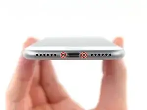
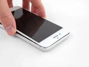
Heating the lower edge of the iPhone will help soften the adhesive securing the display, making it easier to open.
-
Use a hairdryer or prepare an iOpener and apply it to the lower edge of the phone for about 90 seconds in order to soften up the adhesive underneath.
-
-
-
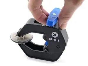
The next two steps demonstrate the Anti-Clamp, a tool we designed to make the opening procedure easier. If you aren't using the Anti-Clamp, skip down two steps for an alternate method.
-
Pull the blue handle towards the hinge to disengage opening mode.
-
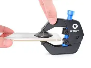
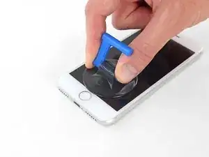
Position the suction cups near the bottom edge of the iPhone just above the home button—one on the front, and one on the back.
-
Push down on the cups to apply suction to the desired area.
-
-
-
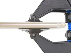
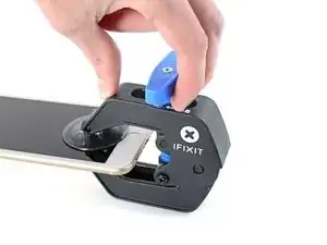
Push the blue handle away from the hinge to engage opening mode.
-
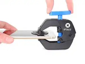
Turn the handle clockwise until you see the cups start to stretch.
-
Wait one minute to give the adhesive a chance to release and for the bottom of the screen to open.
-
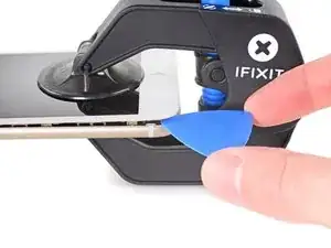
Insert an opening pick under the screen when the Anti-Clamp creates a large enough gap.
-
Skip the next two steps.
-
-
-
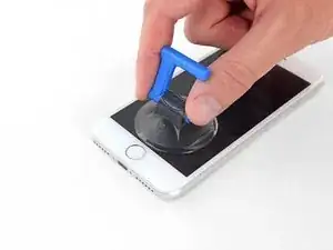
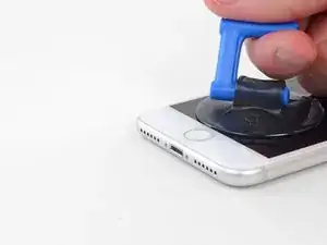
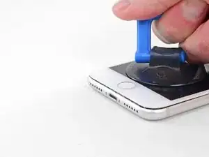
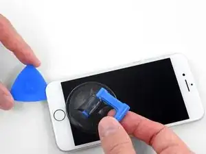
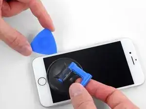
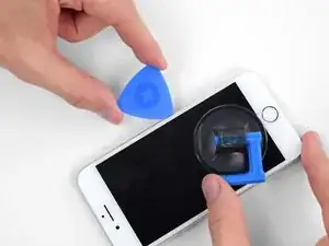
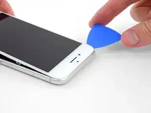
Pull up on the suction cup with firm, constant pressure to create a slight gap between the front panel and rear case.
-
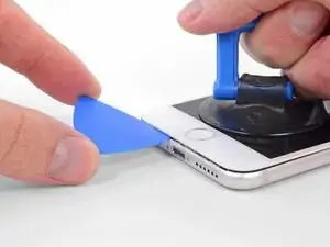
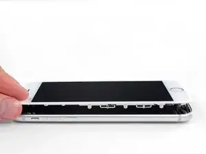
Insert an opening pick into the gap.
-
-
-
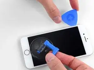
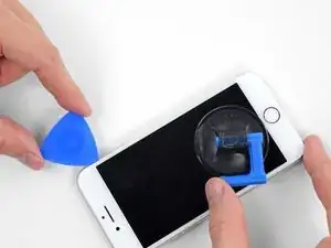
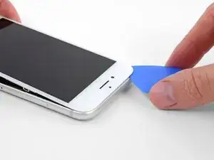
Slide the opening pick up the left edge of the phone starting at the lower edge and moving towards the volume control buttons and silent switch, breaking up the adhesive holding the display in place.
-
Stop near the top left corner of the display.
-
-
-
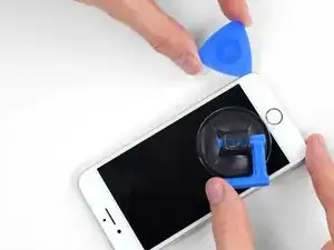
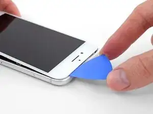
Re-insert your tool at the lower right corner of the iPhone, and slide it around the corner and up the right side of the phone to separate the adhesive.
-
-
-
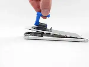
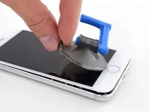
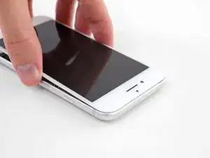
Gently pull up on the suction cup to lift up the bottom edge of the display.
-
Pull on the small nub on the suction cup to remove it from the front panel.
-
-
-
Slide an opening pick underneath the display around the top left corner and along the top edge of the phone to loosen the last of the adhesive.
-
-
-
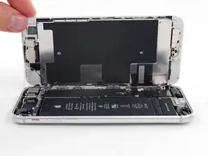
Slide the display assembly slightly down (away from the top edge of the phone) to disengage the clips holding it to the rear case.
-
-
-
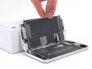
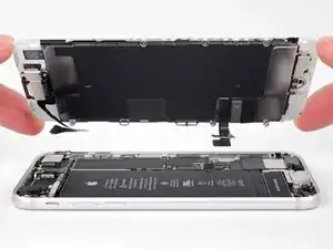
Open the iPhone by swinging the display up from the left side, like the back cover of a book.
-
Lean the display against something to keep it propped up while you're working on the phone.
-
-
-
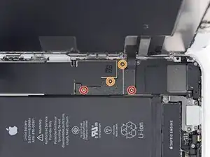
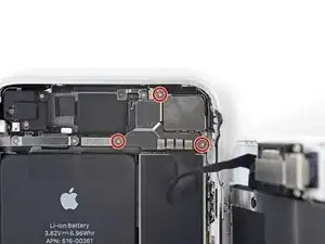
Remove four Phillips screws securing the lower display cable bracket to the logic board, of the following lengths:
-
Two 1.3 mm screws
-
Two 2.8 mm screws
-
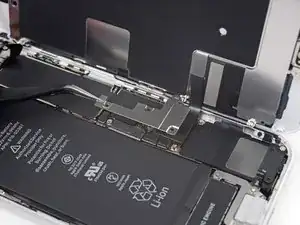
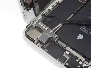
Remove the bracket.
-
-
-
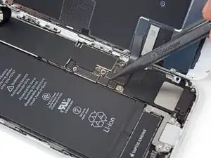
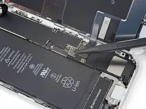
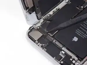
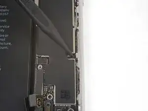
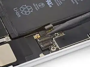
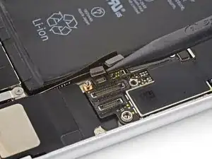
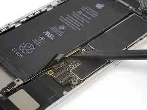
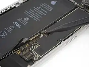
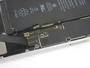
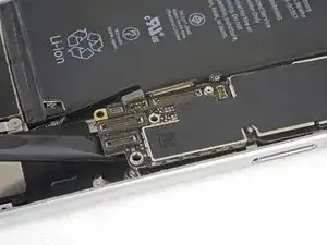
Use the point of a spudger to pry the battery connector out of its socket in the logic board.
-
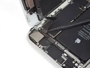
Bend the battery connector cable slightly away from the logic board to prevent it from accidentally making contact with the socket and providing power to the phone during your repair.
-
-
-
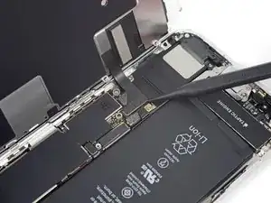
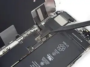
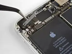
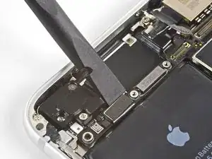
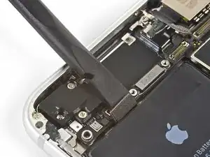
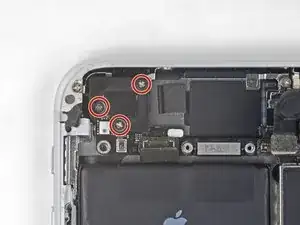
Remove the three 1.3 mm Phillips screws securing the bracket over the front panel sensor assembly connector.
-
Remove the bracket.
-
-
-
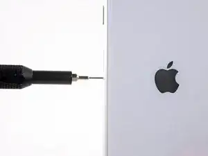
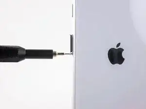
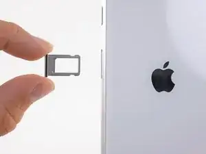
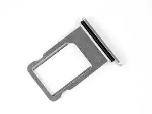
Insert a SIM card eject tool, bit, or a straightened paperclip into the small hole in the SIM card tray.
-
Press to eject the tray.
-
-
-
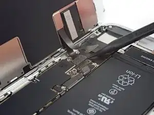
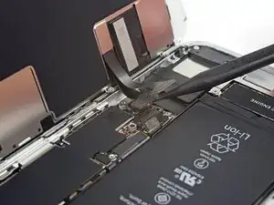
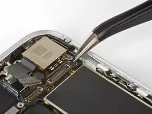
Use the flat end of a spudger to disconnect the camera cable connector by prying it straight up from its socket.
-
-
-
Remove the two screws securing the rear-facing camera bracket:
-
One 3.0 mm standoff screw
-
One 3.1 mm Phillips screw
-
-
-
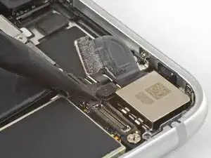
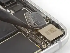
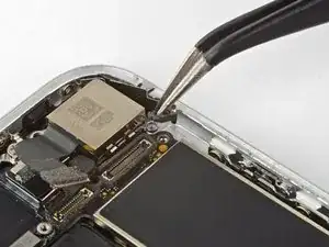
Use the point of a spudger to disconnect the flash connector from its socket by prying it straight up.
-
-
-
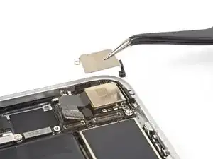
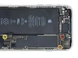
Remove the two screws securing the upper cable bracket:
-
One 2.9 mm Phillips screw
-
One 1.3 mm Phillips screw
-
-
-
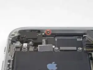
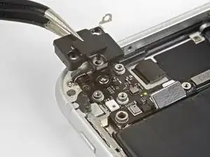
Remove the 1.4 mm Phillips screw securing the antenna component to the top of edge of the case.
-
-
-
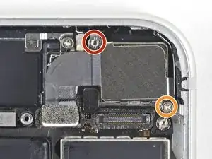
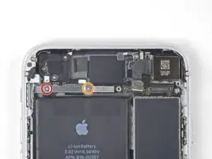
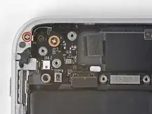
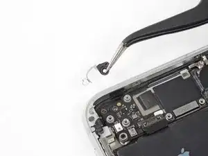
Remove the two Phillips screws securing the grounding clip at the top left edge of the logic board:
-
One 1.5 mm Phillips screw
-
One 2.6 mm Phillips screw
-
-
-
Remove the three screws securing the motherboard:
-
One 1.8 mm Phillips screw
-
One 2.5 mm standoff screw
-
One 2.2 mm standoff screw
-
-
-
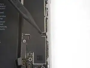
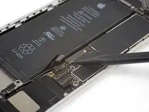
Use the flat end of a spudger to gently lift the battery connector end of the logic board up.
-

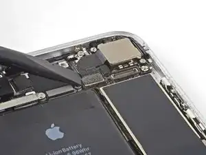
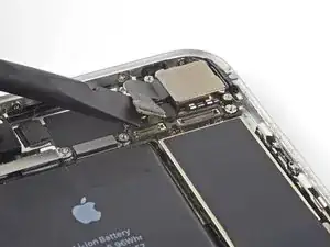
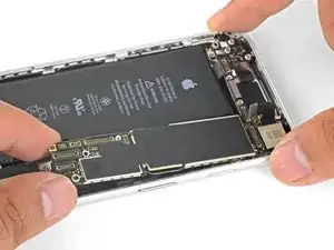
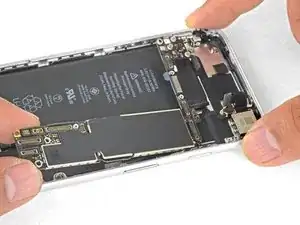
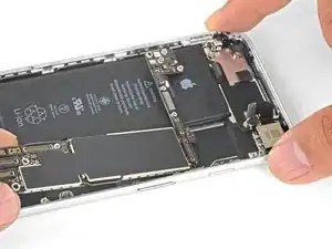
To reassemble your device, follow the above steps in reverse order.
Take your e-waste to an R2 or e-Stewards certified recycler.
Repair didn’t go as planned? Check out our Answers community for troubleshooting help.

2 comments
Where can you buy a logic board
perfect, thanks!
wii8 -
just how long are those screws- i turn and turn and turn and the lift off is soooo slight, seemingly insignificant…
An. Jahnke -
I would recommend, from the very beginning, dumping all tools out of the kit (if you got it) and using that white paper tool box as a tray to organize the screws and braces in. It’s nice to work over because it catches screws well and makes it easy to see them if you drop any.
Johnny Emrica -
That’s a great idea thank you
Mohamed Dekkiche -
Screw to the left of the charging port will not come out. Screw on the right came out no problem. Any ideas?
Bill Maher -