Einleitung
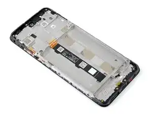
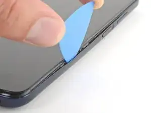
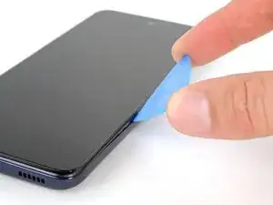
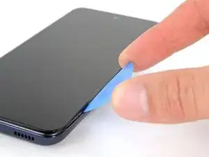
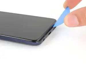
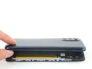
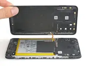
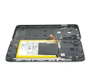
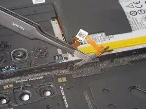
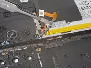
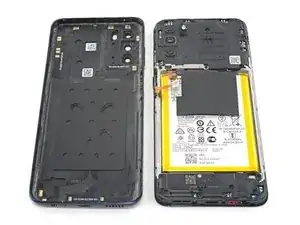
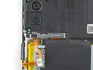
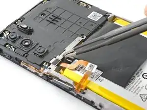
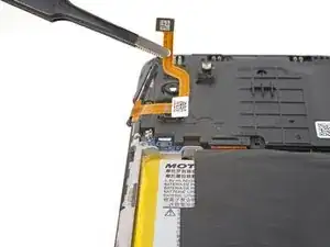
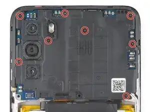
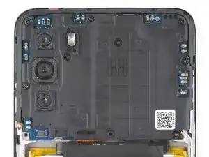
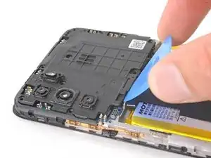
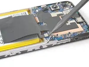
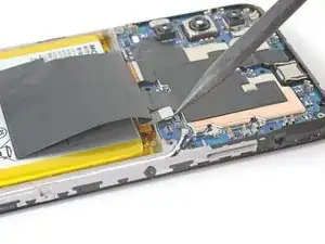
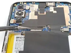
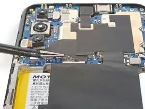
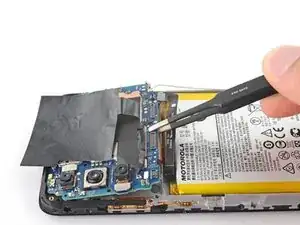
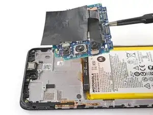
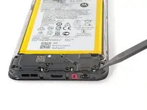
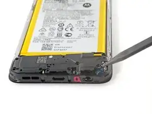
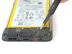
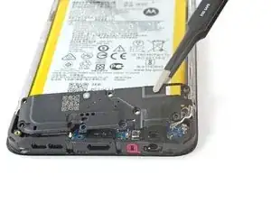
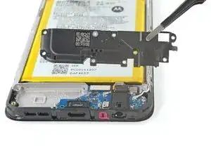
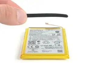
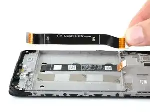
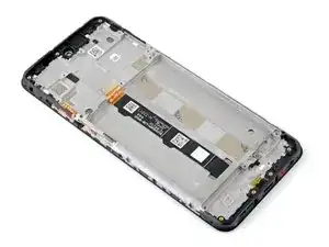
This guide demonstrates how to replace the screen in your 2022 Motorola Moto G with a genuine Motorola part.
Note: This procedure is for a screen that's pre-installed in a new frame (a.k.a. chassis). You'll need to transplant all of your phone's internals to the new screen. If you're replacing the display panel by itself, follow this guide instead.
Werkzeuge
Ersatzteile
-
-
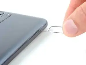
Insert a SIM card eject tool or a straightened paperclip into the hole adjacent to the SIM card tray.
-
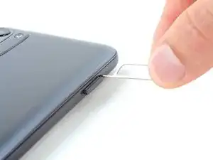
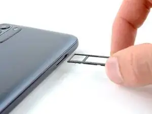
Press firmly to eject the tray.
-
-
-
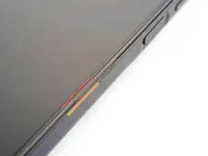
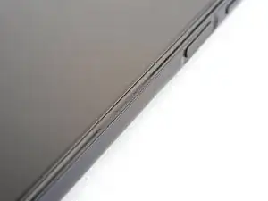
Take note of the following seams along the edge of the phone:
-
Screen seam: This seam separates the display panel from the frame. Don't pry at this seam.
-
Bezel seam: This is where the plastic back cover meets the rest of the phone. It's held in place by plastic clips. This is where you should pry.
-
-
-
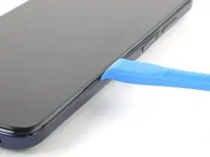
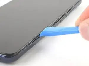
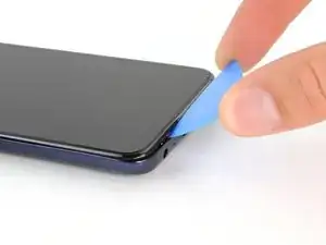
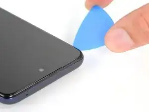
Insert an opening tool in the bezel seam halfway between the bottom-right corner of the phone and the power button.
-
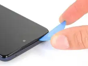
Insert an opening pick in the gap you just created.
-
-
-
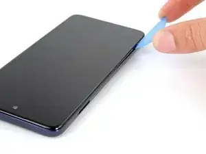
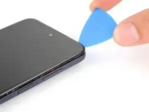
Slide your opening pick toward the bottom-right corner of the back cover and release the clips.
-
-
-
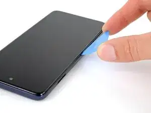
Continue sliding your opening pick towards the bottom left corner to unclip the bottom edge of the back cover.
-
-
-
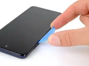
Slide your opening pick toward the top left corner to unclip the left side of the back cover.
-
-
-
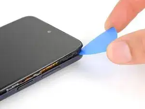
Slide your pick around the top right corner to release the last clips securing the back cover.
-
-
-
With SIM card slot facing you, swing the back cover open and away from you like you're opening a book.
-
Rest the cover parallel to the frame.
-
-
-
Use tweezers or your fingers to unhook the power button's rubber arm from its recess and remove it.
-
-
-
Use a PH00 screwdriver to remove the two 3.9 mm-long screws securing the power button cable bracket.
-
-
-
Use your fingers or a pair of blunt nose tweezers to grab and remove the bracket from the power button cable.
-
-
-
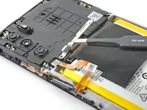
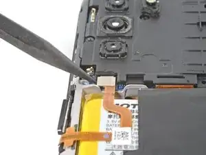
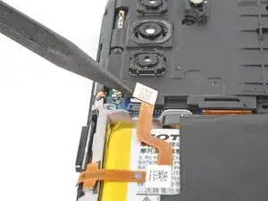
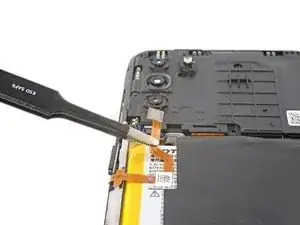
Use the pointed end of a spudger to pry up and disconnect the power button's press connector.
-
-
-
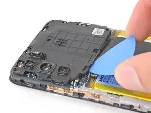
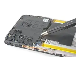
Use your Phillips screwdriver to remove the eight 3.9 mm-long screws securing the motherboard cover.
-
-
-
Insert an opening pick between the bottom-left corner of the cover and the motherboard.
-
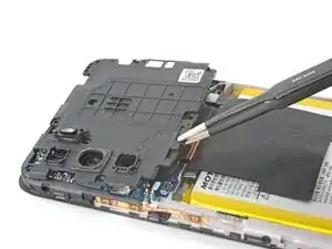
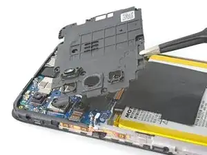
Pry up to release the cover's small clips securing it to the frame.
-
-
-
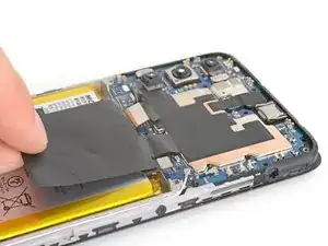
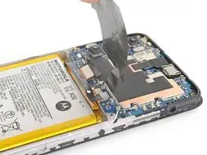
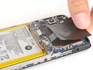
Fold the graphite heat film away from the battery to expose the lower section of the motherboard.
-
-
-
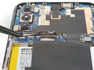
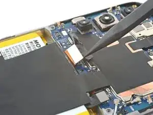
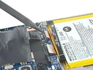
Use the pointed end of a spudger to pry and disconnect the board cable's press connector.
-
-
-
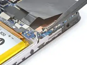
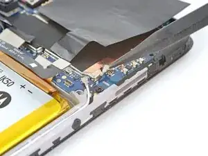
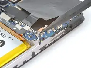
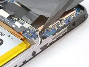
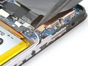
Use the pointed end of your spudger to pry and disconnect the head of the black antenna cable.
-
Free the cable from the clip below the head of the connector.
-
-
-
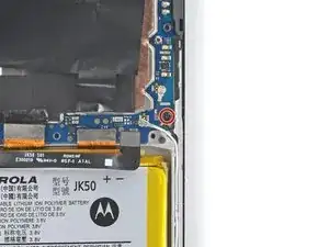
Use your Phillips screwdriver to remove the 2.9 mm-long screw from the bottom-right corner of the motherboard.
-
-
-
Insert the pointed end of a spudger between the lower left of the motherboard and the frame.
-
Lift upward on this bottom edge to free the motherboard from the frame.
-
-
-
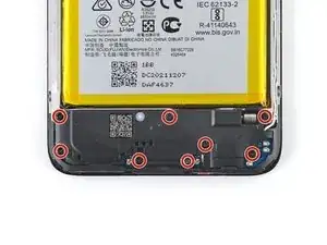
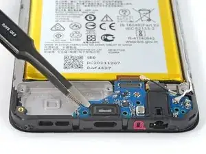
Use your Phillips screwdriver to remove the eight 4 mm-long screws from the loudspeaker plate.
-
-
-
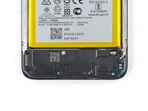
Insert the pointed end of a spudger under bottom right corner of the loudspeaker plate.
-
Pry upward on the plate until it frees from its recess.
-
-
-
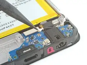
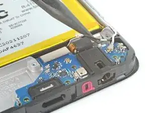
Use the pointed end of your spudger to pry and disconnect the head of the white antenna cable.
-
-
-
Pry and disconnect the head of the black antenna cable.
-
Free the cable from its grounding clip in the top-right of the daughterboard.
-
-
-
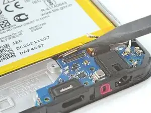
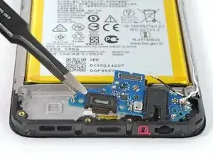
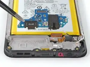
Use the pointed end of your spudger to pry and disconnect the board cable's press connector.
-
-
-
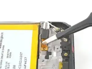
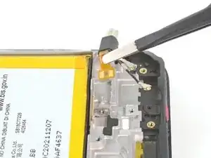
Use the pointed end of a spudger, or a pair of tweezers, to peel the vibration motor's cable from the frame.
-
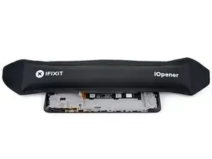
If the cable feels stuck, use a heated iOpener, hair dryer, or heat gun to soften the adhesive.
-
Remove the vibration motor from the frame.
-
-
-
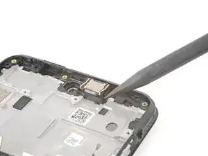
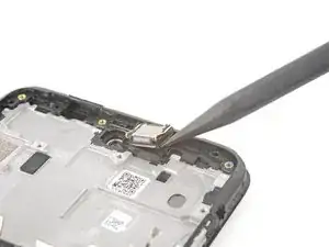
Insert the point of a spudger into the small gap on the lower right side of the earpiece speaker's recess.
-
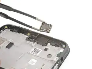
Pry up on the speaker and remove it.
-
-
-
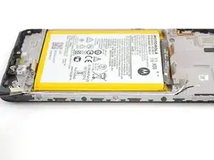
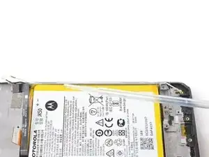
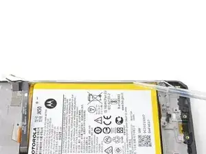
Apply the isopropyl alcohol into the gaps between the sides of the battery and the frame.
-
-
-
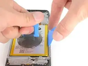
Apply a suction cup to the battery, as close to the center of the right edge as possible.
-
Insert an opening pick between the right edge of the battery and the frame.
-
Pull on the suction cup and pry the battery upward.
-
Remove the battery from the frame.
-
-
-
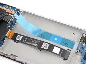
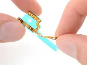
Place the sticky side of the adhesive on the frame and remove the blue liner.
-
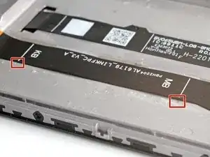
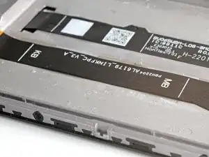
The frame has very small notches to assist positioning the board ribbon cable.
-
-
-
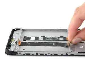
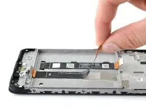
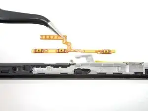
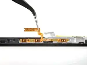
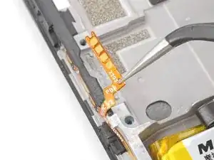
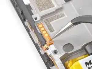
Place the long end of the side button cable onto the left edge of the frame.
-
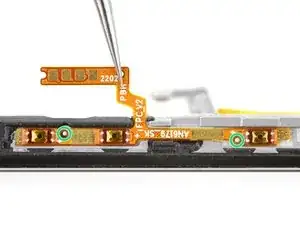
Use the alignment pegs to position the cable.
-
Press along the cable to adhere it to the frame.
-
-
-
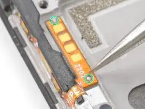
Fold the short end of the side button cable over the edge of the frame.
-
Use the alignment pegs to place the cable on the frame.
-
Press along the cable to adhere it to the frame.
-
Compare your new replacement part to the original part—you may need to transfer remaining components or remove adhesive backings from the new part before you install it.
To reassemble your device, follow these instructions in reverse order. Apply new adhesive where necessary after cleaning the relevant areas with isopropyl alcohol (>90%).
Take your e-waste to an R2 or e-Stewards certified recycler.
Repair didn’t go as planned? Try some basic troubleshooting, or ask our Answers community for help.
