Introduction
Follow this guide to replace the battery in your iPad Pro 12.9" 4th generation.
This guide is written with an A2229 (Wi-Fi only) model iPad Pro. If you have the cellular model, use this guide as a general reference, but you may need to perform extra disassembly not covered in this guide.
If your battery is swollen, take appropriate precautions.
Tools
-
-
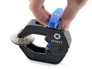
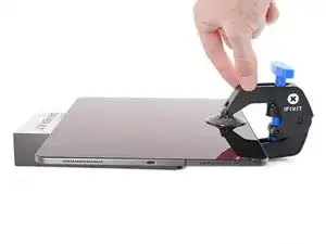
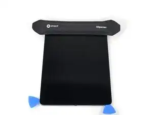
Elevate the iPad enough for the Anti-Clamp's arms to rest above and below the screen.
-
Pull the blue handle towards the hinge to disengage opening mode.
-
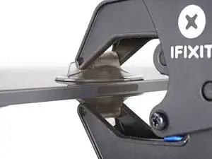
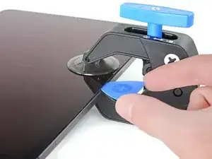
Position the suction cups near the right edge of the iPad—one on the front, and one on the back.
-
Push down on the cups to apply suction to the desired area.
-
-
-
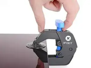
Push the blue handle away from the hinge to engage opening mode.
-
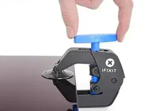
Turn the handle clockwise until you see the cups start to stretch.
-
Wait one minute to give the adhesive a chance to release and present an opening gap.
-
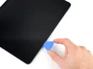
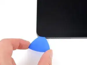
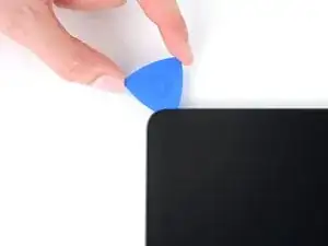
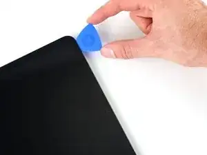
Insert an opening pick under the screen when the Anti-Clamp creates a large enough gap.
-
Skip the next step.
-
-
-
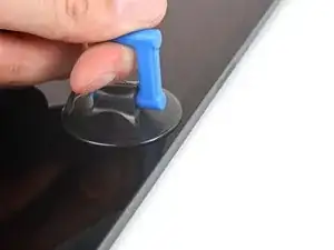
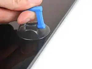
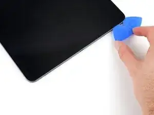
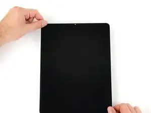
Apply a suction handle to the screen as close to the center of the right edge as possible.
-
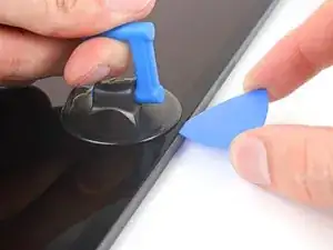
Pull up on the suction handle with a strong, steady force to create a small gap between the frame and screen.
-
Insert an opening pick into the gap.
-
-
-
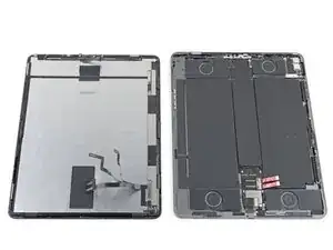
One magnet begins 2 cm from the top edge and is 2.5 cm long.
-
The second magnet begins 3 cm from the bottom edge and is 2.5 cm long.
-
-
-
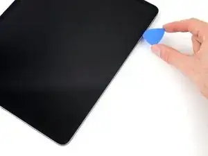
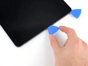
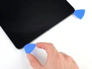
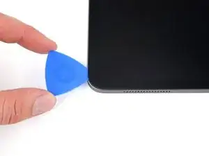
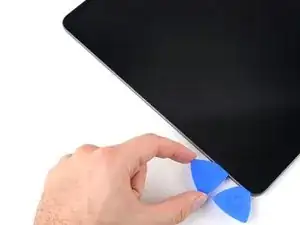
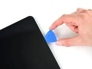
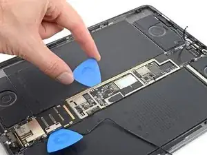
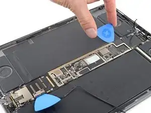
Slide your opening pick back and forth along the right edge of the screen to slice the adhesive.
-
-
-
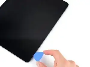
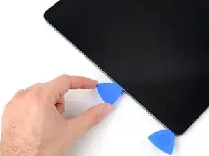
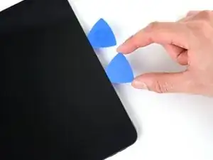
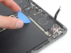
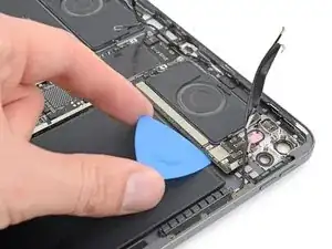
Rotate your opening pick around the bottom right corner of the screen.
-
Leave your pick in the bottom right corner to prevent the adhesive from resealing.
-
-
-
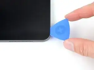
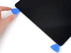
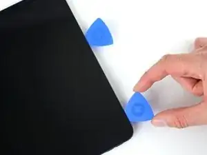
Insert a second opening pick in the bottom right corner of the screen.
-
Slide your pick to the bottom left corner to slice the bottom edge adhesive.
-
-
-
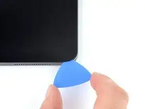
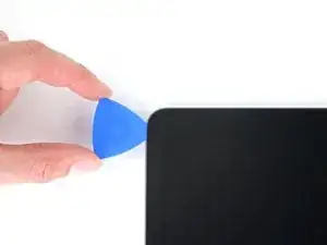
Rotate your opening pick around the bottom left corner of the screen.
-
Leave your pick in the bottom left corner to prevent the adhesive from resealing.
-
-
-
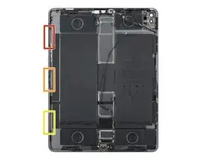
The upper cutout begins 4 cm from the top edge and is 2.5 cm long.
-
The middle cutout is exactly in the middle of the frame and is 2.5 cm long.
-
The lower cutout begins 4 cm from the bottom edge and is 2.5 cm long.
-
-
-
Insert a third opening pick in the bottom left corner of the screen.
-
Slide your pick to the top left corner to slice the left edge adhesive.
-
-
-
Rotate your opening pick around the top left corner of the screen.
-
Leave your pick in the top left corner to prevent the adhesive from resealing.
-
-
-
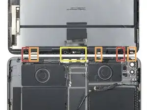
While the top edge adhesive softens, note the following:
-
There are two ambient light sensors near the corners. Only insert the very tip of your pick here to avoid damaging them.
-
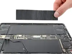
There are three strips of heat dispersion tape. Angle your pick upward as you slice here.
-
The front-facing camera assembly is in the center of the top edge. Don't insert your pick here to avoid damaging them.
-
-
-
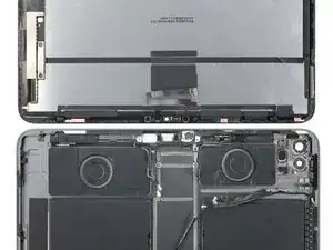
Slide your opening pick 9 cm toward the center of the top edge to slice the adhesive, paying attention to the spots mentioned in the previous step.
-
-
-
Insert a fourth opening pick to the right of the front camera assembly, 4 cm from the previous opening pick and 9 cm from the right edge of the screen.
-
Slide your pick to the top right corner to slice the remaining adhesive.
-
-
-
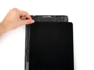
Grab two opposing corners of the screen and gently shift it around to separate it from the frame.
-
Shift the screen towards the bottom right corner of the frame until the ribbon cable near the top edge is uncovered.
-
-
-
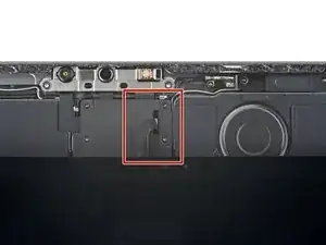
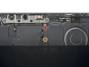
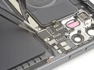
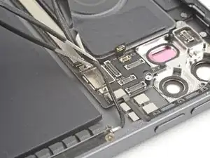
Use your Phillips screwdriver to remove the two screws securing the upper cable shield:
-
One 1.8 mm-long screw
-
One 2.0 mm-long screw
-
-
-
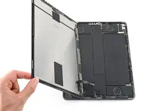
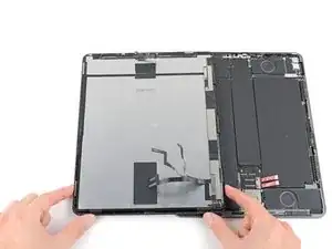
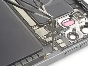
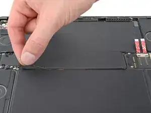
Grip the right edge of the screen and fold it open like a book.
-
Lay the screen down over the left edge of the iPad.
-
-
-
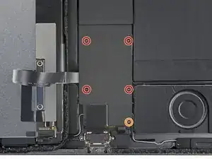
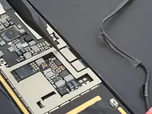
Use your Phillips screwdriver to remove the five screws securing the lower cable shield:
-
Four 1.1 mm screws
-
One 2.0 mm screw
-
-
-
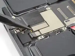
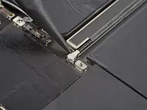
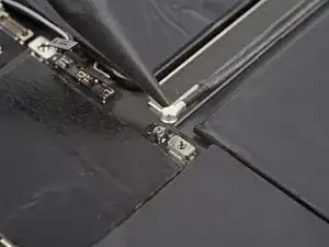
Use your Phillips screwdriver to remove the 1.7 mm screw securing the battery connector to the logic board.
-
-
-
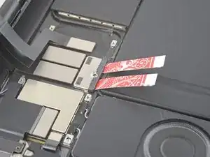
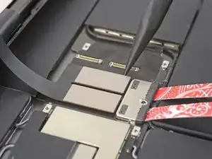
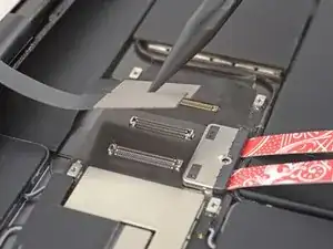
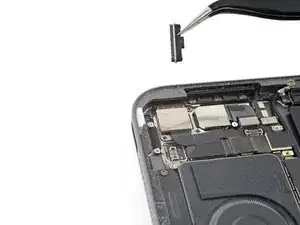
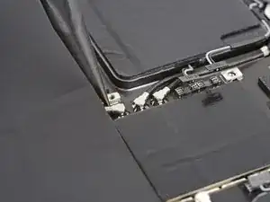
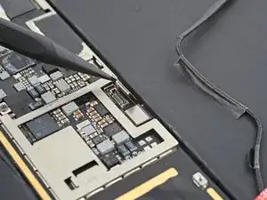
Use the point of your spudger to pry up and disconnect the upper two display press connectors from the logic board.
-
-
-
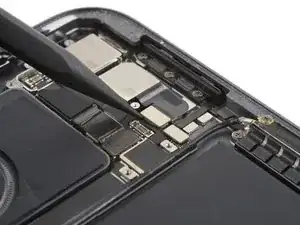
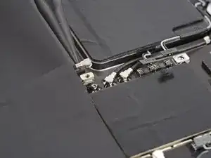
Use the point of your spudger to pry up and disconnect the lower two display press connectors from the logic board.
-
-
-
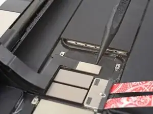
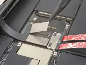
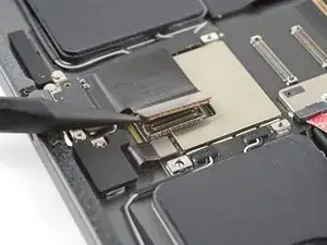
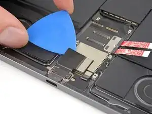
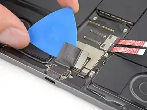
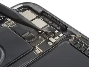
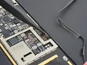
Use the point of your spudger to pry up and disconnect the USB-C port press connector from the logic board.
-
-
-
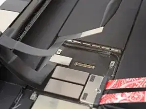
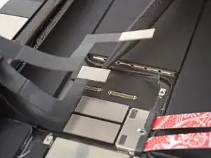
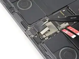
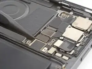
Grab and remove the USB-C port from its recess in the frame.
-
Use caution not to lose the grounding contacts on either side of the USB-C recess.
-
-
-
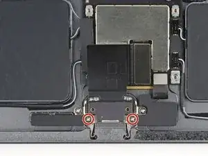
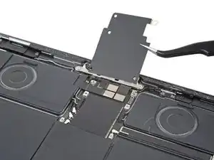
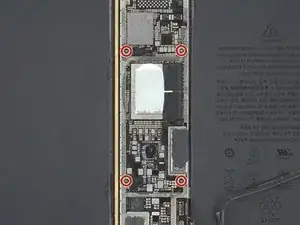
Use your Phillips screwdriver to remove the four screws securing the upper cable shield:
-
Three 1.1 mm screws
-
One 2.0 mm screw
-
-
-
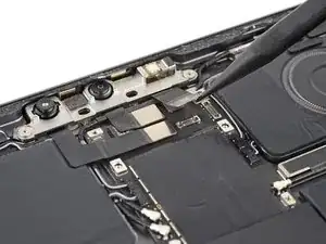
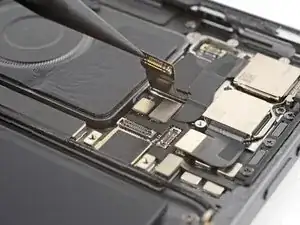
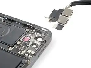
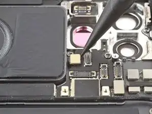
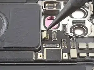
Use the point of your spudger to pry up and disconnect the three press connectors for the IR dot-projector, front camera, and Face ID camera.
-
-
-
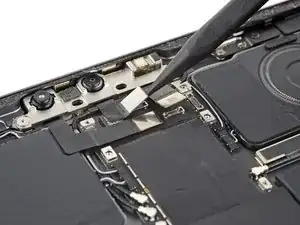
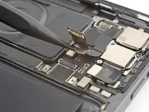
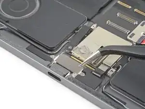
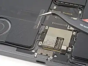
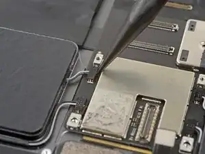
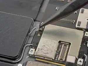
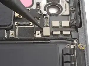
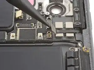
Use blunt nose tweezers to grab and peel the left and middle front camera assembly cables from the logic board.
-
-
-
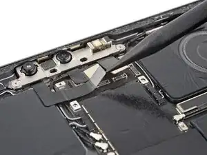
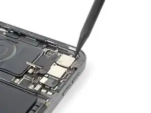
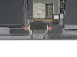
Use your T3 Torx screwdriver to remove the two 2.2 mm screws securing the front camera assembly bracket.
-
-
-
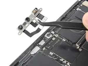
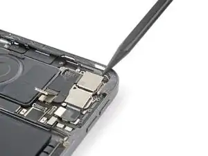
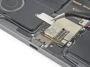
Use tweezers or your fingers to grab and remove the front camera assembly bracket from its recess.
-
-
-
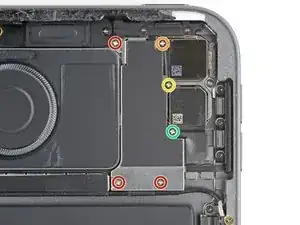
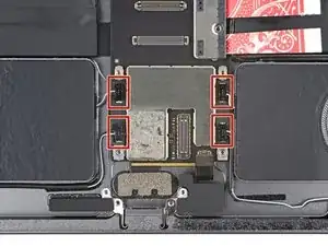
Use your Phillips screwdriver to remove the six screws securing the rear camera shield:
-
Three 1.2 mm screws
-
One 2.8 mm screw
-
One 2.6 mm screw
-
One 1.8 mm screw
-
-
-
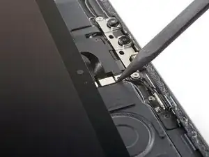
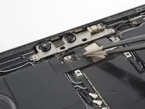
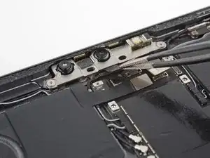
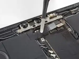
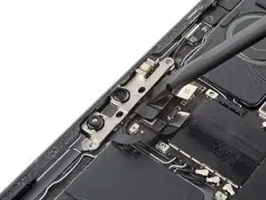
Use the point of your spudger to pry up and disconnect both of the power button's press connectors.
-
-
-
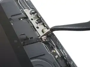
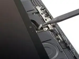
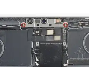
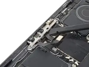
Use your Phillips screwdriver to remove the two 2.3 mm screws securing the power button assembly.
-
-
-
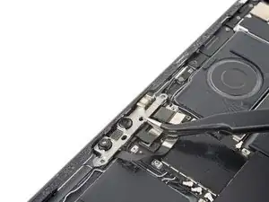
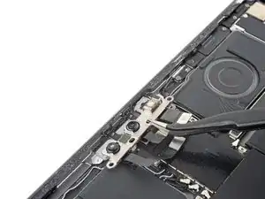
Insert the point of your spudger between the left edge of the power button assembly and the frame.
-
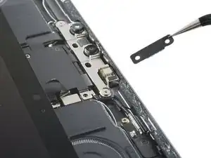
Pry the assembly up from its recess in the frame.
-
Grab and remove the power button assembly.
-
-
-
Push the power button through its recess from the outside of the frame.
-
Remove the power button.
-
-
-
Use the point of your spudger to pry up and disconnect the wide-angle camera from the logic board.
-
-
-
Use the point of your spudger to pry up and disconnect the LiDAR sensor and ultrawide camera from the logic board.
-
-
-
Insert the point of your spudger between the top right corner of the rear cameras and the frame.
-
Pry the cameras up until you can grab them with tweezers or your fingers.
-
Remove the rear cameras.
-
-
-
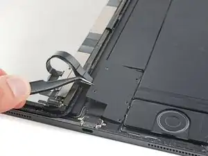
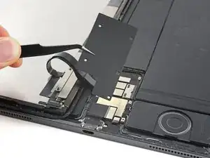
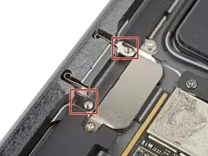
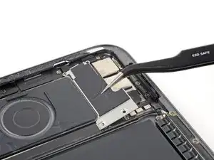
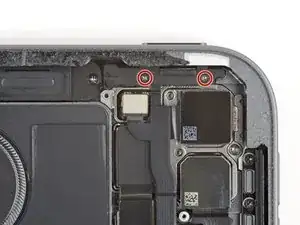
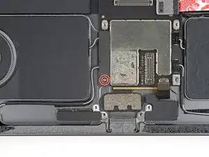
Use your Phillips screwdriver to remove the two 1.9 mm screws securing the Smart Connector cover.
-
-
-
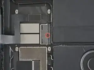
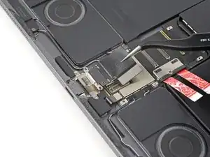
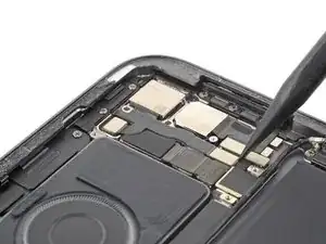
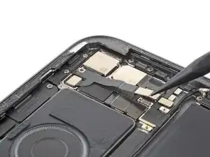
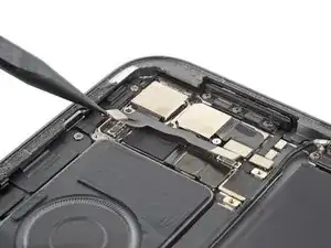
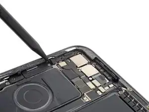
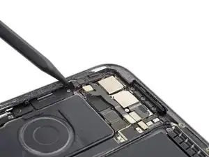
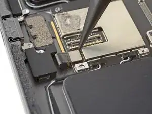
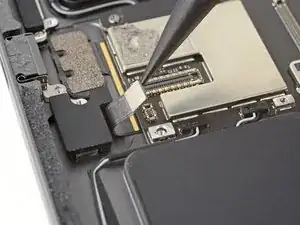
Use the point of your spudger to pry up and disconnect the Smart Connector from the bottom of the logic board.
-
-
-
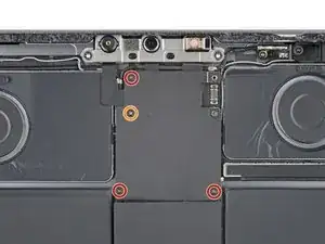
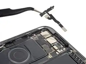
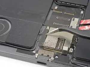
Use your Phillips screwdriver to remove the 2.0 mm screw securing the lower left speaker cable shield.
-
-
-
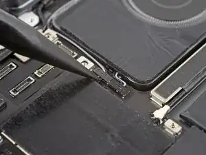
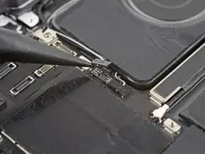
Use the point of your spudger to pry up and disconnect the lower speaker press connectors.
-
Disconnect all four connectors for the lower speakers.
-
-
-
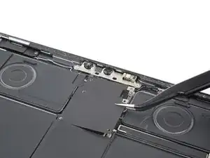
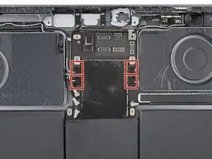
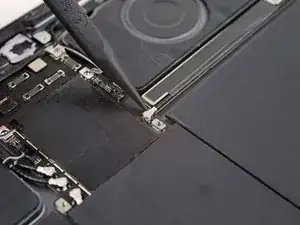
Use the point of your spudger to pry up and disconnect all four upper speaker press connectors.
-
-
-
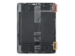
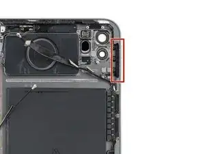
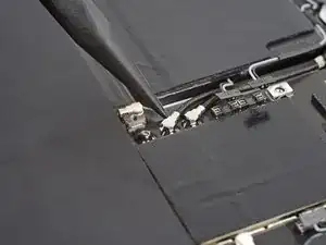
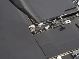
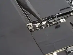
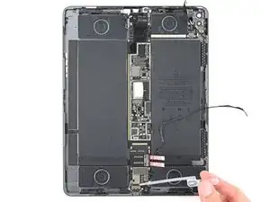
Use the point of your spudger to pry up and disconnect the upper antenna cable from the right edge of the logic board.
-
-
-
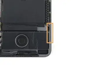
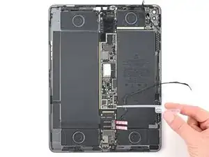
Use the point of your spudger to pry up and disconnect the lower antenna cable from the left edge of the logic board.
-
-
-
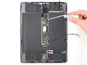
Use the point of your spudger to pry up and disconnect the remaining two antenna cables from the left edge of the logic board.
-
-
-
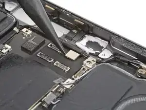
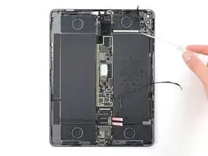
Use the point of your spudger to pry up and disconnect the upper sensor press connector from the logic board.
-
-
-
Use the point of your spudger to pry up and disconnect the rear sensor press connector from the right arm of the logic board.
-
-
-
Use the point of your spudger to pry up and disconnect the volume press connector from the right arm of the logic board.
-
-
-
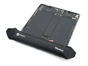
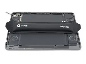
Apply a heated iOpener to the upper antenna cable and right arm of the logic board for two minutes.
-
-
-
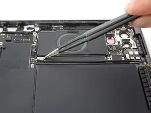
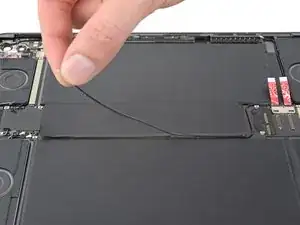
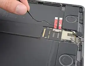
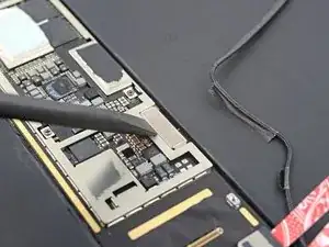
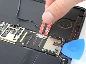
Use blunt nose tweezers or your fingernail to peel the tape securing the upper antenna cable to the right arm of the logic board.
-
-
-
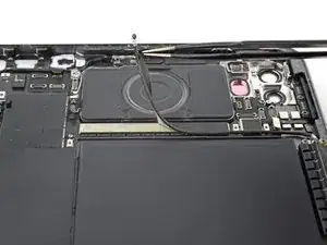
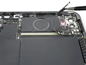
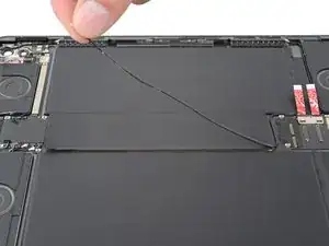
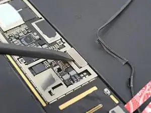
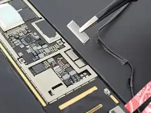
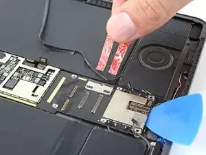
Peel the second strip of tape securing the upper antenna cable to the logic board near the rear camera cutouts.
-
Reposition the cable away from the logic board.
-
-
-
Apply a heated iOpener to the lower antenna cable, located along the left edge of the logic board, for two minutes.
-
-
-
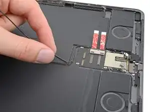
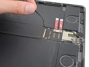
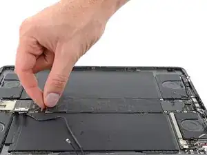
Grab the lower antenna cable, just below its metal connector head.
-
Peel the cable from the left edge of the logic board.
-
-
-
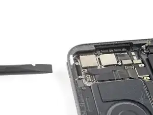
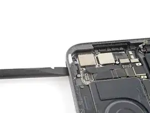
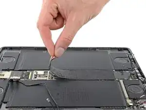
Use your fingers to grab a corner of the logic board cover.
-
Peel and remove the cover from the logic board.
-
-
-
Use the flat end of your spudger to slide the bottom right press connector bracket away from the logic board.
-
Use blunt nose tweezers or your fingers to remove the bracket.
-
-
-
Use the point of your spudger to pry up and disconnect the microphone and Apple Pencil charger press connectors.
-
-
-
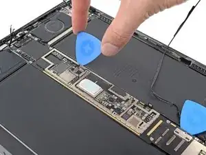
Apply several drops of highly-concentrated isopropyl alcohol (over 90%) to the bottom and right edges of the logic board.
-
Elevate the right edge of the iPad to allow the isopropyl alcohol to flow under the logic board.
-
Wait one minute for the isopropyl alcohol to penetrate.
-
-
-
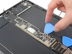
Apply isopropyl alcohol to the right arm and left edge of the logic board.
-
Elevate the left edge of the iPad to allow the isopropyl alcohol to flow under the logic board.
-
Wait one minute for the isopropyl alcohol to penetrate.
-
-
-
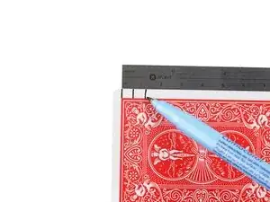
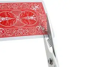
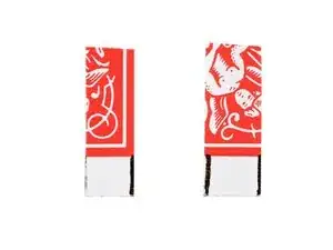
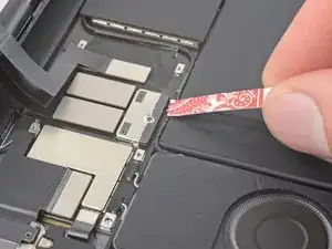
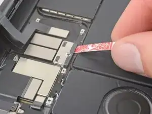
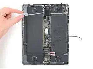
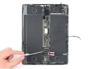
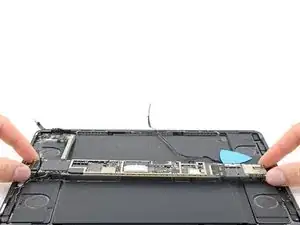
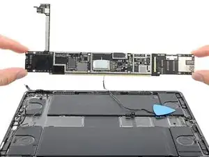
Remove the card strips blocking the battery connector.
-
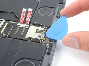
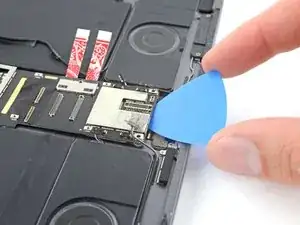
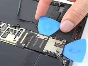
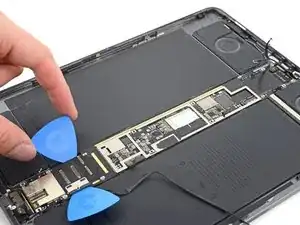
Gently insert the tip of an opening pick between the logic board and the battery connector.
-
Leave this pick inserted until the logic board is completely removed.
-
-
-
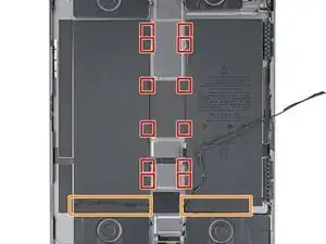
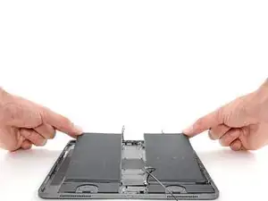
There are twelve stretch-release adhesive pull tabs securing the batteries to the frame.
-
The remaining adhesive secures the battery boards to the bottom of the frame, and has no stretch-release tabs.
-
-
-
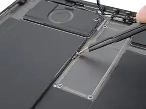
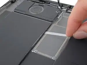
Use blunt nose tweezers or your fingers to peel each stretch-release pull tab away from the battery.
-
Slowly pull the strips straight away from the battery, keeping a low angle to the frame.
-
Give the strips plenty of time to stretch. If a strip breaks off, try to retrieve it and continue pulling.
-
If you removed all 12 stretch-release adhesive strips, skip down three steps.
-
If any strips broke off, follow the next two steps for an alternative method to remove the battery.
-
-
-
Apply several drops of highly-concentrated isopropyl alcohol (over 90%) to the inside edges of the batteries near any broken strips of stretch-release adhesive.
-
Elevate each edge of the iPad to allow the isopropyl alcohol to flow under the batteries.
-
Wait one minute for the isopropyl alcohol to penetrate.
-
-
-
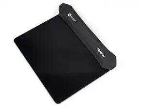
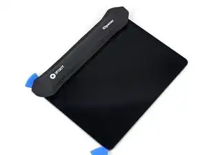
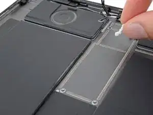
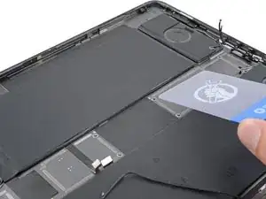
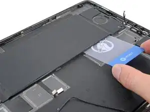
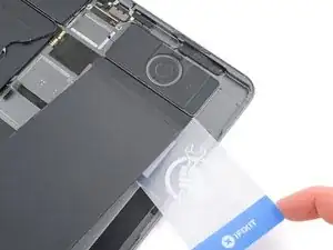
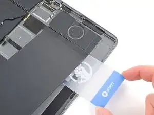
Slide a plastic card under the left battery near any broken strips of stretch-release adhesive.
-
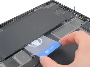
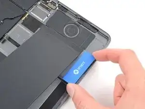
Slide the plastic card along the length of the battery to separate any remaining adhesive. Don't slide your card underneath the battery boards.
-
Repeat this step for the right battery.
-
-
-
Elevate the top edge of the iPad and raise the left battery to allow access underneath the battery board.
-
Apply a few drops of isopropyl alcohol to the battery board.
-
Repeat this step for the right battery.
-
-
-
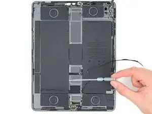
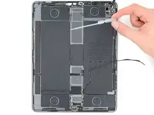
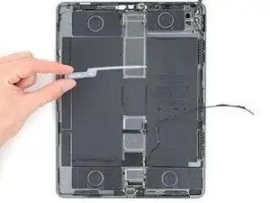
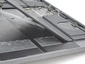
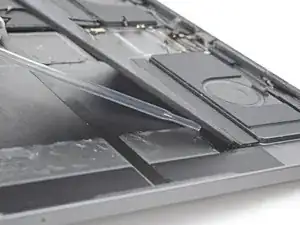
Lay your iPad flat and slide your plastic card at a slight angle under the outer edge of the left battery board.
-
Straighten the plastic card and fully insert it under the battery board to slice the adhesive.
-
Repeat this step for the right battery.
-
-
-
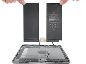
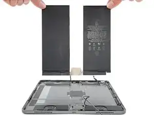
Grab both halves of the battery by the upper corners and remove them from the frame.
-
Clean any remaining adhesive with a few drops of isopropyl alcohol and a lint-free cloth.
-


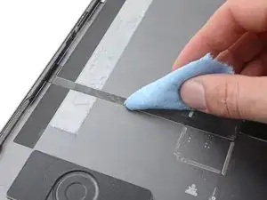
Compare your new replacement battery to the original one—you may need to transfer remaining components or remove adhesive backings from the new battery before installing.
To reassemble your device, follow these instructions in reverse order.
Take your e-waste to an R2 or e-Stewards certified recycler.
Repair didn’t go as planned? Try some basic troubleshooting, or ask our iPad Pro 12.9" 4th Gen Answers community for help.
