Einleitung
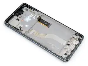
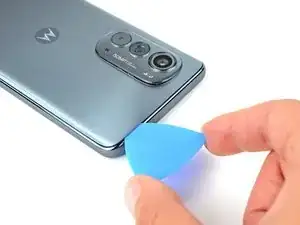
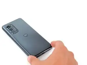
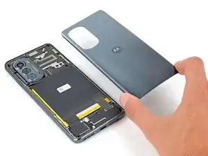
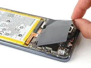
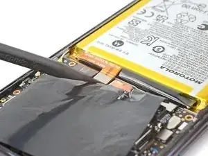
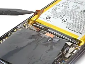
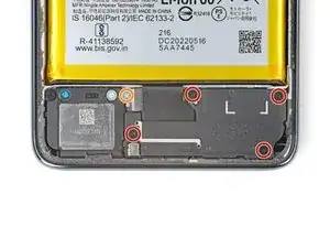
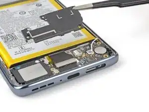
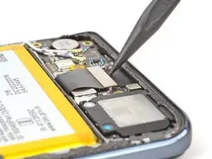
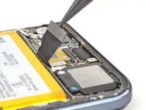
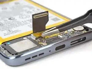
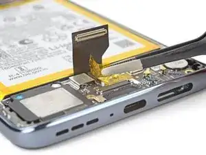
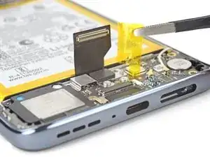
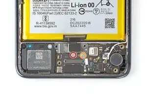
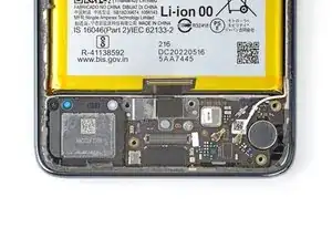
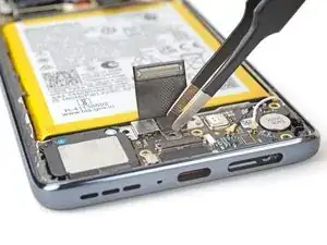
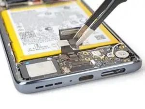
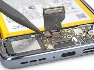
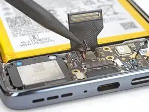
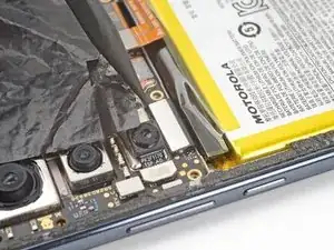
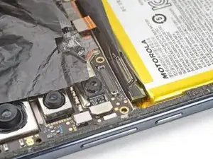
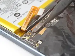
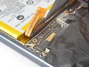
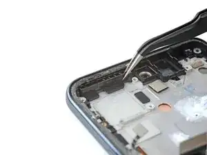
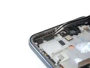
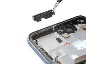
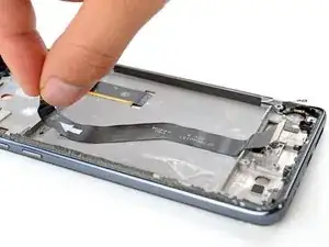
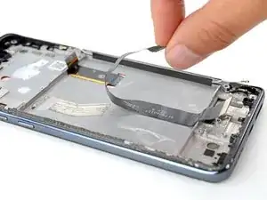
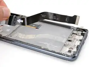
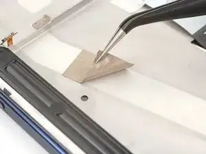
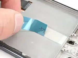
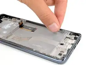
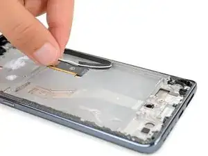
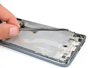
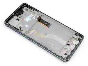
Use this guide to remove or replace the screen on your Motorola Edge (2022).
This guide is for the official Motorola replacement part.
Note: Follow this guide to replace a screen that's pre-installed in a new frame (a.k.a. chassis). You'll need to transplant all of your phone's internals to the new screen. If you are replacing the display panel only, follow this guide.
For your safety, discharge the battery below 25% before disassembling your phone. This reduces the risk of a dangerous thermal event if the battery is accidentally damaged during the repair. If your battery is swollen, take appropriate precautions.
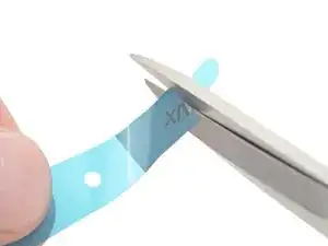
You'll need replacement adhesive to complete this repair. If you bought an iFixit Fix Kit it will include extra Antenna Bracket Adhesive that's not necessary for this specific model.
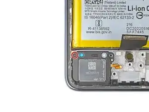
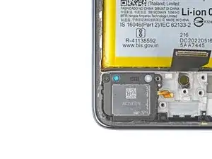
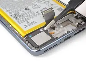
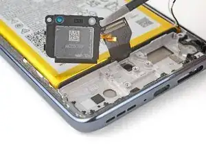
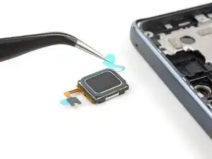
Note: Some photos in this guide show the earpiece speaker removed, leading to visual discrepancies. This will not affect the guide procedure.
Werkzeuge
Ersatzteile
-
-
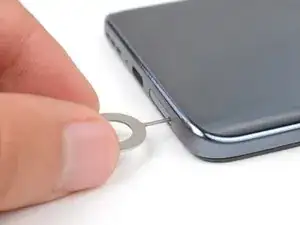
Insert a SIM eject tool, bit, or straightened paperclip into the SIM card tray hole on the bottom edge of the phone.
-
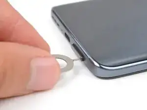
Press the SIM eject tool into the sim card tray hole to eject the SIM card tray.
-
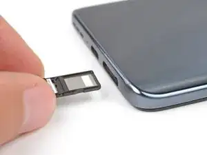
Use your fingers or tweezers to remove the SIM card tray.
-
-
-
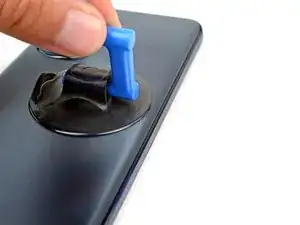
Apply a suction cup to the back of the phone, as close to the middle of the right edge as possible.
-
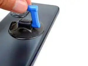
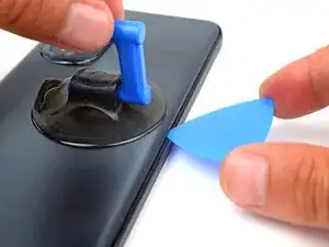
Pull up on the suction cup with a strong, steady force to create a gap between the back cover and the frame.
-
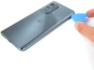
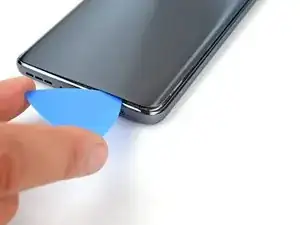
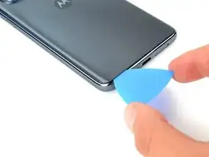
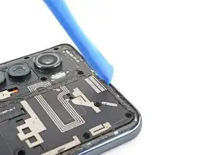
Insert an opening pick into the gap.
-
-
-
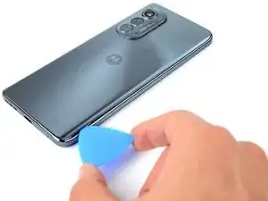
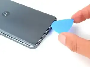
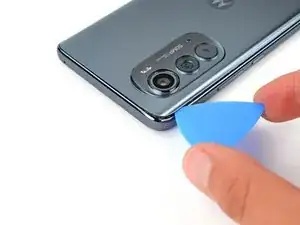
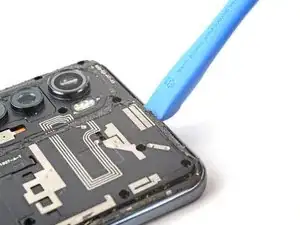
Slide the pick along the right edge to slice the adhesive.
-
Leave the pick in the bottom right edge to prevent the adhesive from resealing.
-
-
-
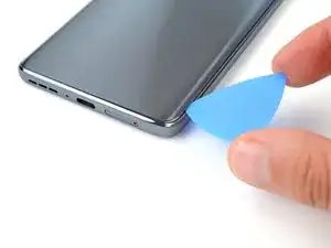
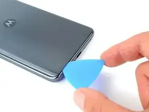
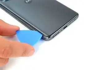
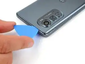
Slide the pick along the bottom edge to slice the adhesive.
-
Leave the pick in the bottom left edge to prevent the adhesive from resealing.
-
-
-
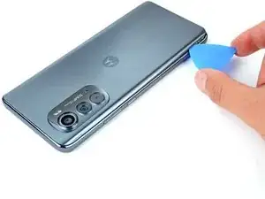
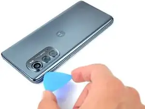
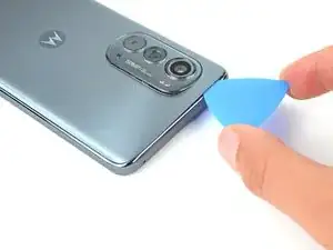
Slide the pick along the edge to slice the adhesive.
-
Leave the pick in the top left edge to prevent the adhesive from resealing.
-
-
-
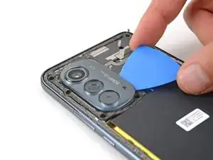
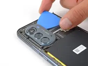
Insert an opening pick between the right edge of the camera bezel and the motherboard cover.
-
Slide the pick back and forth along the edge to slice the adhesive.
-
-
-
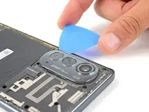
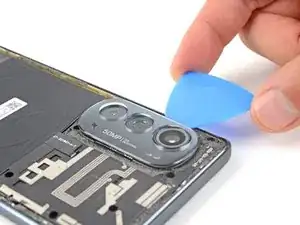
Insert an opening pick between the left edge of the camera bezel and the motherboard cover.
-
Slide the pick back and forth along the edge to slice the adhesive.
-
-
-
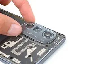
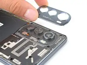
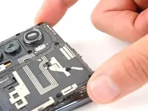
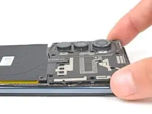
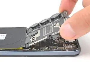
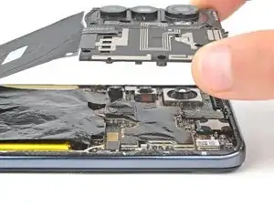
Lift the camera bezel from the phone and remove it.
-
This is a good point to test your phone's functionality before sealing it up. Use this guide to run a hardware test. Be sure to power your phone back down completely before you continue working.
-
If you are replacing the fingerprint sensor or screen assembly, use this guide to calibrate the fingerprint sensor.
-
Follow this guide to replace the back cover and camera bezel adhesive.
-
-
-
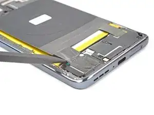
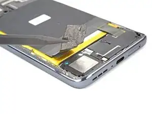
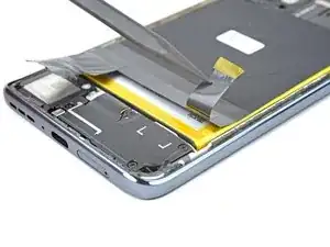
Insert the pointed end of a spudger underneath the tape that connects the wireless charging coil to the speaker on the bottom left of the phone.
-
Slowly lift the spudger up until the tape detaches from the speaker.
-
-
-
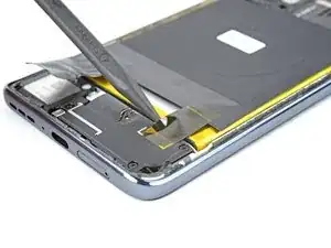
Insert a spudger underneath the tape that connects the wireless charging coil to the daughterboard cover on the bottom right of the phone.
-
Slowly lift the spudger up until the tape detaches.
-
-
-
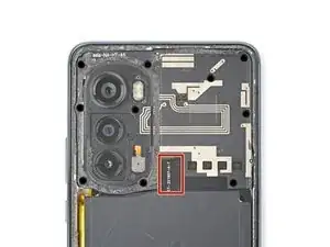
There's adhesive under the motherboard cover that secures the cover to the motherboard.
-
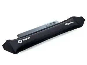
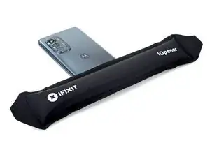
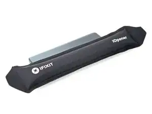
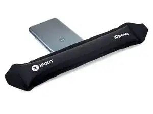
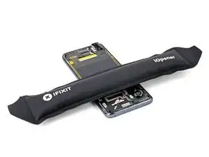
Apply a heated iOpener between the bottom of the motherboard cover and the top of the battery for two minutes.
-
-
-
Insert an opening tool between the motherboard cover and the midframe.
-
Pry up with the opening tool until you are able to grab the motherboard cover with your fingers.
-
-
-
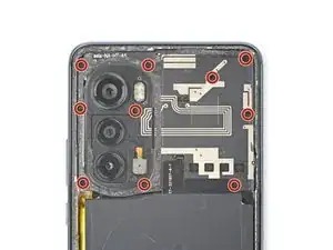
Use a Phillips screwdriver to remove the five screws securing the daughterboard cover:
-
Four 4.1 mm screws
-
One 3 mm screw
-
-
-
Insert a spudger under the daughterboard cover on the bottom right corner of the phone.
-
Pry up with the spudger to release the clips securing the cover.
-
-
-
Use the pointed end of a spudger to pry up and disconnect the interconnect cable's press connector from the daughterboard.
-
-
-
Use your fingers or tweezers to peel back and remove the tape on the fingerprint sensor cover.
-
Set the tape aside for reassembly.
-
-
-
Use a Phillips screwdriver to remove the two 3 mm screws:
-
One screw securing the fingerprint sensor cover.
-
One screw securing the daughterboard.
-
-
-
Use the pointed end of a spudger to pry up and disconnect the fingerprint sensor's press connector.
-
-
-
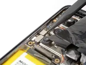
Use the pointed end of a spudger to pry up and disconnect the black antenna's coaxial connector.
-
Use the spudger to push the antenna up and away from the phone until the cable is freed from the clip securing it to the daughterboard.
-
-
-
Insert the pointed end of a spudger in the gap between the daughterboard and frame near the right edge of the phone.
-
Gently pry up to release the clips securing the daughterboard.
-
-
-
Use the flat side of a spudger to pry the fingerprint sensor from the frame.
-
Use your fingers or tweezers to remove the fingerprint sensor from the phone.
-
-
-
Apply a few drops of high-concentration (90% or higher) isopropyl alcohol under the vibration motor and its contact pad to loosen the adhesive securing them.
-
Wait one minute to allow the isopropyl alcohol to penetrate the adhesive.
-
-
-
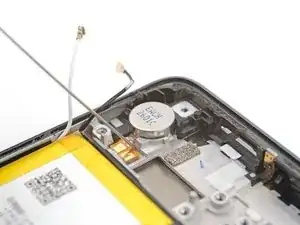
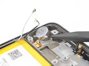
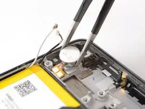
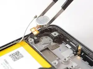
Insert the pointed end of a spudger in the gap between the vibration motor and frame.
-
Pry up with the spudger to separate the vibration motor from the frame.
-
-
-
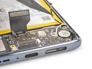
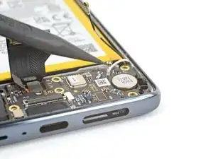
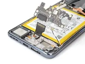
Use the pointed end of a spudger to pry up and disconnect the interconnect cable's press connector.
-
-
-
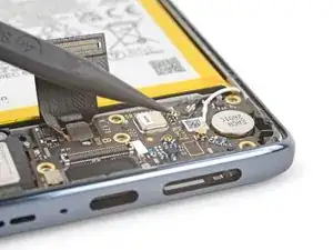
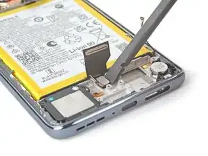
Use the pointed end of a spudger to pry up and disconnect the button assembly's press connector.
-
-
-
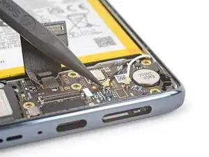
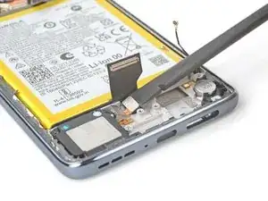
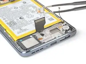
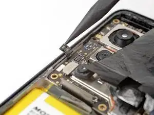
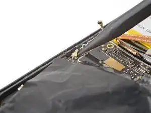
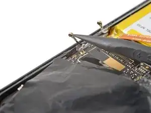
Use the pointed end of a spudger to pry up and disconnect the white antenna's coaxial connector.
-
-
-
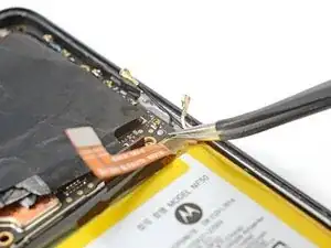
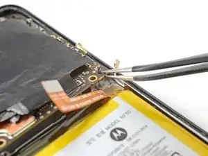
Use a pair of tweezers to grip the bottom right corner of the motherboard near the peg on the right edge of the phone.
-
Pull the motherboard up and over the peg with a slow, steady force. This should release a few clips securing the motherboard.
-
-
-
Insert the pointed end of a spudger under the middle of the motherboard's bottom edge.
-
Gently pry up on the motherboard to release the clips securing it.
-
-
-
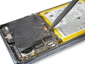
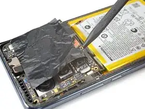
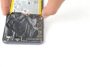
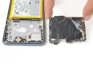
Remove the motherboard from the phone.
-
Clean off the old thermal paste from the midframe and motherboard using isopropyl alcohol and a microfiber cloth. Apply new thermal paste before reassembly.
-
Ensure that all of the cables that connect to the motherboard (interconnect, battery, antenna, display, and button assembly) are out of they way so they do not get stuck under the motherboard when it's reinserted.
-
-
-
Apply a few drops of high-concentration (90% or higher) isopropyl alcohol under the loudspeaker's contact pad to loosen the adhesive securing it.
-
-
-
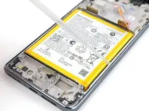
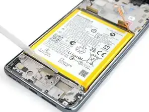
Apply a few drops of high-concentration (90% or higher) isopropyl alcohol to the gaps along the battery's edges.
-
Tilt the device as you apply alcohol to help it flow under the battery.
-
Wait one minute to allow the isopropyl alcohol to penetrate the adhesive.
-
-
-
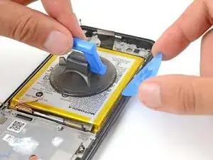
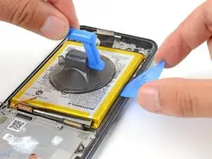
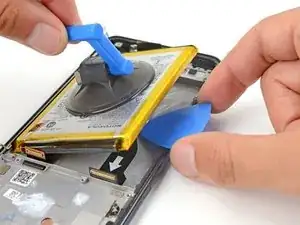
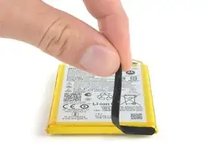
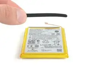
Apply a suction cup to the battery.
-
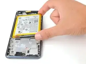
Pull up on the suction cup with strong, steady force to separate the battery from the frame.
-
Insert an opening pick into the gap.
-
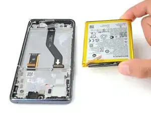
Continue to pull up on the suction cup with a strong, steady force while sliding the opening pick back and forth to slice the adhesive. Continue this process until the battery separates from the midframe.
-
-
-
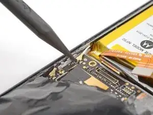
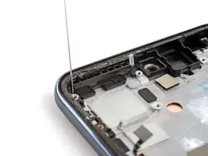
Apply a few drops of high-concentration (90% or higher) isopropyl alcohol on either side of the plastic buffer on the top left of the phone.
-
-
-
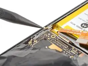
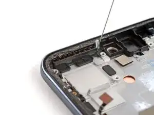
Use tweezers to grip the buffer.
-
Tilt the buffer towards the bottom of the phone to disconnect it from the lip in the midframe.
-
Pull up and remove the buffer.
-
-
-
If necessary, cut the adhesive blocks to fit into contours of the cable channel. The adhesive doesn't need fit the contours perfectly.
-
Peel the adhesive blocks from the adhesive sheet.
-
Place the adhesives in the board cable channel. Space them evenly through the channel.
-
Peel any remaining plastic liners to expose the adhesive.
-
-
-
Use tweezers to peel off the larger, rectangular liner.
-
Align the speaker in its proper orientation over its recess and push down to secure it.
-
Use tweezers to remove the liner on the speaker's flex cable.
-
Insert the flex cable in its groove on the frame and press down to secure it.
-
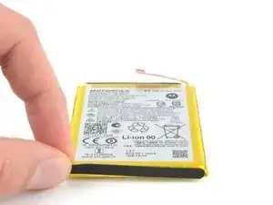
Compare your new replacement part to the original part—be sure to transfer remaining components and remove adhesive backings from the new part before installing.
To reassemble your device, follow the instructions in reverse order.
If you bought an iFixit Fix Kit it will include extra Antenna Bracket Adhesive that's not necessary for this specific model.
Take your e-waste to an R2 or e-Stewards certified recycler.
Repair didn’t go as planned? Try some basic troubleshooting, or ask our Answers community for help.
