Einleitung

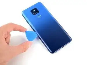
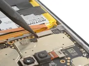
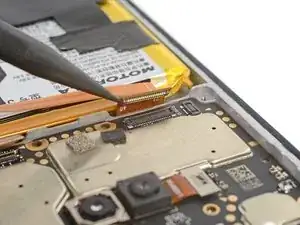
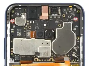
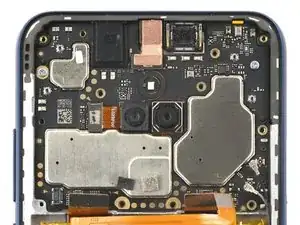
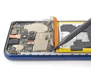
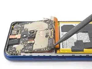
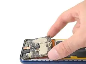
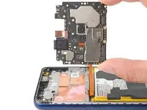
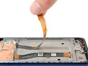
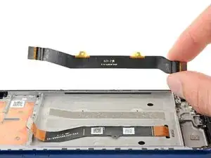
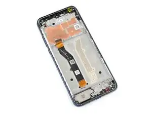
Follow this guide to replace the screen in your 2021 Motorola Moto G Play with a genuine Motorola part.

Note: This procedure is for a screen that's pre-installed in a new frame (a.k.a. chassis). You'll need to transplant all of your phone's internals to the new screen. If you're replacing the display panel by itself, follow this guide instead.

For your safety, discharge the battery below 25% before disassembling your device. This reduces the risk of fire if the battery is accidentally damaged during the repair. If your battery is swollen, take appropriate precautions.

  1. byDqSDo4rONRYCgL
    byDqSDo4rONRYCgL
    nPuuXgLfWLBemsnm
    opLMXDAeakxmAadD
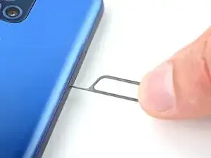
    • Insert a SIM card eject tool or a straightened paperclip into the hole adjacent to the SIM card tray.

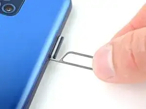
    • Press firmly to eject the tray.

    • The SIM card may fall out.

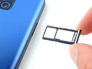
    • Grab and remove the SIM card tray from the phone.

    • Reinsert the SIM card tray with the SIM card recess facing the screen.

  2. qgQ1lHBRnuCrMf4A
    • Discharge your battery to 25% or lower and power off your phone before you begin.

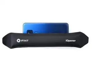
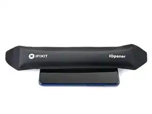
    • Heat an iOpener and apply it to the left edge of the cover for two minutes.

    • A hair dryer or heat gun may also be used, but be careful not to overheat the phone—the display and internal battery are both susceptible to heat damage.

  3. kBSAWhijB31MWsUt
    kBSAWhijB31MWsUt
    tfVQLJVGTNtuigH2
    133WPNrZdCOAOXYg
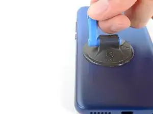
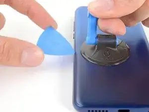
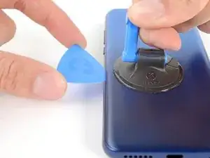
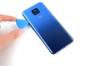
    • Apply a suction cup to the back cover, as close to the center of the left edge as possible.

    • Pull up on the suction cup with strong, steady force to create a gap between the cover and the frame.

    • Insert an opening pick into the gap.

  4. jTCbwSHbPbJjmxoi
    jTCbwSHbPbJjmxoi
    UKi1UMeCaXbJSvMg
    VbCijygl1nakCe41
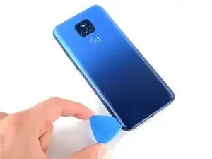
    • Slide your opening pick back and forth along the left edge to slice through the adhesive.

    • Leave the pick in at the bottom left corner to prevent the adhesive from resealing.

  5. n3vVVrshSlhKUOo5
    n3vVVrshSlhKUOo5
    ZjQGODHwtoSQJWQ6
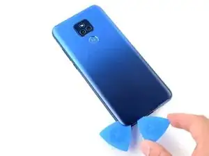
    • Insert and slide a second opening pick to the bottom right corner to slice through the adhesive.

    • Leave the pick inserted to prevent the bottom edge from resealing.

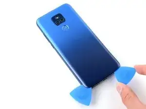
    • Repeat this process for the right and top edges of the cover.

  6. uqQuRoos4vFKrKGB
    uqQuRoos4vFKrKGB
    U6MYCaXqBWNMGBL1
    UXJHlk2FMdHpxxHA
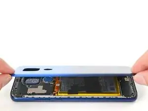
    • The fingerprint reader is connected to the motherboard by a fragile cable. You must free it before pulling the cover off.

    • Grab and lift the bottom edge of the cover.

    • As you lift the back cover, press and unstick the fingerprint reader from it.

  7. DyJLOQrMUIsErS3b
    DyJLOQrMUIsErS3b
    ebyguh2aDUOGFdkF
    laQRGQXtRLeTren4
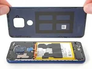
    • Grab and remove the back cover.

    • If your back cover is still sticking to the frame, slide the pick around the edges of the phone to slice through any remaining adhesive.

    • Reassembly notes:

    • This is a good point to test your phone before sealing it up. Follow this guide to perform a hardware test. Be sure to power your phone back down completely before you continue working.

    • To adhere the back cover with custom-cut adhesives, follow this guide.

    • To adhere the back cover with tape, follow this guide.

  8. Y6aCq5DFtLBKpJuw
    Y6aCq5DFtLBKpJuw
    hH3NfEPeHxcCKKMk
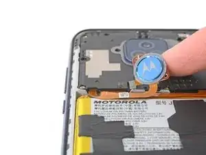
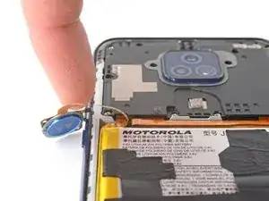
    • Flip the fingerprint reader to the left, away from the phone.

    • Don't fold or sharply bend the ribbon cable.

  9. vuhLCmIG1PmKIQMS
    vuhLCmIG1PmKIQMS
    dtBoOYajXXhpjCyY
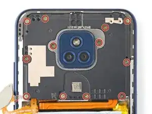
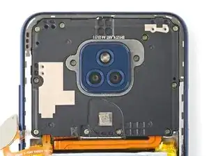
    • Use your Phillips screwdriver to remove the twelve 3.9 mm-long screws securing the motherboard cover.

  10. X4ow4ygsRaka22s1
    X4ow4ygsRaka22s1
    RKqLJXDNgPqqWOuO
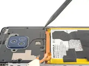
    • Insert the pointed end of a spudger between the bottom right corner of the motherboard cover and the frame.

    • Pry the cover upward until you can grab it with your fingers.

  11. rQ4c34OHNEGUOTtd
    rQ4c34OHNEGUOTtd
    MFcjhoSCZEHqgExO
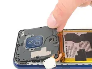
    • Grab the bottom edge of the motherboard cover and remove it from the frame.

  12. EFFHRxF5emOtURkC
    EFFHRxF5emOtURkC
    x4rrLgshsKlcJWcC
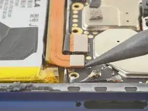
    • Use the pointed end of your spudger to pry and disconnect the battery's press connector.

    • To re-attach press connectors, carefully align and press down on one side until it clicks into place, then repeat on the other side. Don't press down on the middle. If the connector is misaligned, the pins can bend and cause permanent damage.

  13. AVteICXoiV1jS3ow
    AVteICXoiV1jS3ow
    NPjDMNxyRSRsxGVj
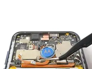
    • Use the pointed end of your spudger to pry and disconnect the fingerprint reader's press connector.

    • The gold arrow indicates the direction to pry from.

  14. P6ROhipdikMYXcWX
    P6ROhipdikMYXcWX
    Sx1cvawo1HBlCdPL
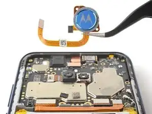
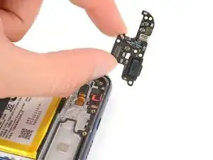
    • Use your fingers or tweezers to remove the fingerprint reader.

    • Be careful while handling the fragile ribbon cable.

  15. T34l15UFqfyGrSNI
    T34l15UFqfyGrSNI
    yBZN2R3NJVP3xX6V
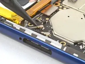
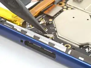
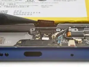
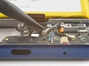
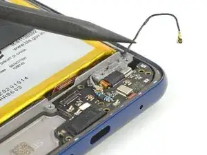
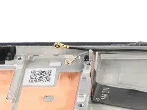
    • Use the pointed end of your spudger to pry and disconnect the gray antenna cable.

    • Pry on the metal head of the connector only. Avoid lifting the cable itself as much as possible.

    • During reassembly, these can be tricky to reconnect. Hold the connector in place over its socket and press down with the flat end of a spudger. The connector should snap into place.

  16. hS2xoxeCenfkoVtw
    hS2xoxeCenfkoVtw
    UfkRKpP1PPoRpIUV
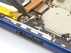
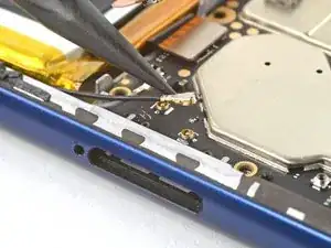
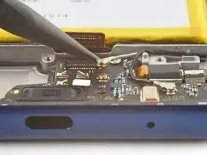
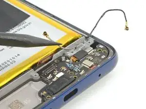
    • Repeat the previous step for the black antenna cable.

  17. ddM4gVJoJuPIF1FH
    ddM4gVJoJuPIF1FH
    nDNAHsjUg1OLaBNM
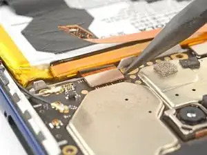
    • Use the pointed end of your spudger to pry and disconnect the board cable's press connector.

  18. UgrXYtkoOCiDaAqF
    UgrXYtkoOCiDaAqF
    KxwnpHxLIp6FxxiW
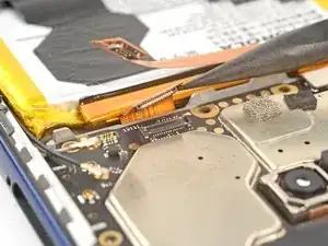
    • Use the pointed end of your spudger to pry and disconnect the display's press connector.

  19. 5ZwAbkibxiIPqajy
    5ZwAbkibxiIPqajy
    wpLa4bqqQJly5whJ
    • Use your Phillips screwdriver to remove the two 2.5 mm-long screws securing the motherboard.

  20. vnXUh4xVOGn2PrTU
    vnXUh4xVOGn2PrTU
    LDhfN1JT2pfKc63E
    • Insert the pointed end of your spudger between the bottom left edge of the motherboard and the frame.

    • Lift the motherboard from its recess.

    • Be sure the loose cables don't catch on the motherboard as it's removed.

  21. dGlX42baKMriLhSa
    dGlX42baKMriLhSa
    BIIBAhrFwHug4p2C
    • Grab the motherboard by its bottom corners and remove it.

    • During reassembly, make sure no cables or connectors become trapped underneath the motherboard.

  22. TctAsBVwVQNUHevd
    TctAsBVwVQNUHevd
    bF2WqoF3pHWoZbvA
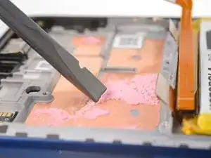
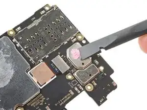
    • Follow this guide to remove excess thermal paste and prepare the frame and motherboard for reassembly.

  23. Xs2q1Dguy6AUTmGh
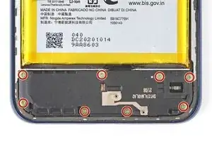
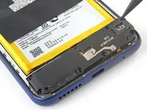
    • Use your Phillips screwdriver to remove the eight 3.8 mm-long screws securing the loudspeaker.

  24. VqaPLwvppsOfVSlV
    VqaPLwvppsOfVSlV
    AUBikEb6WqOdwCIV
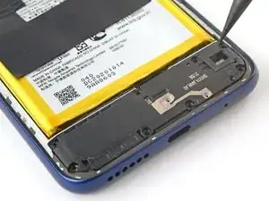
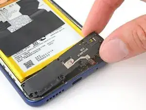
    • Insert your spudger between the top right corner of the loudspeaker and the frame.

    • Pry up to release the loudspeaker.

  25. iTloFTPCwJK5ub2n
    iTloFTPCwJK5ub2n
    1bDPyhejdGQGGYOg
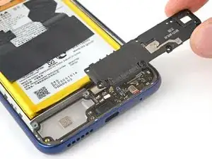
    • Grab the loudspeaker with your fingers and remove it.

  26. QUN6x1KupbGmYvXs
    QUN6x1KupbGmYvXs
    Cd2RK6sCBQPcJNWA
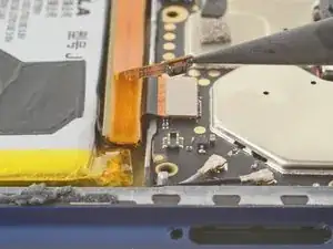
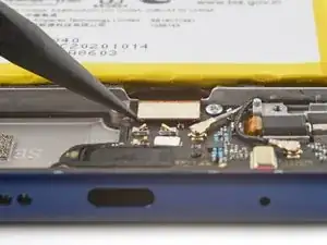
    • Use the pointed end of your spudger to pry and disconnect the board cable's press connector.

    • To re-attach press connectors, carefully align and press down on one side until it clicks into place, then repeat on the other side. Don't press down on the middle. If the connector is misaligned, the pins can bend and cause permanent damage.

  27. b5EBKCWjGQGMlR3m
    b5EBKCWjGQGMlR3m
    RwUNpJBjpeGD5sZd
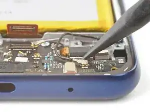
    • Use the pointed end of your spudger to pry and disconnect the gray antenna cable.

    • Pry on only the metal head of the connector. Avoid lifting the cable itself as much as possible.

    • Free the cable from the retaining clip.

    • During reassembly, these can be tricky to reconnect. Hold the connector in place over its socket and press down with the flat end of a spudger. The connector should snap into place.

    • During reassembly, be sure to secure the cable to the clip in the daughterboard.

  28. JnwACZ24uGoYQcXF
    JnwACZ24uGoYQcXF
    sBdlSleOeHhN5ELF
    bWJSj2qfmNTSiIFF
    • Repeat the previous step for the black antenna cable.

  29. WAeMOuOVLUqhvEtS
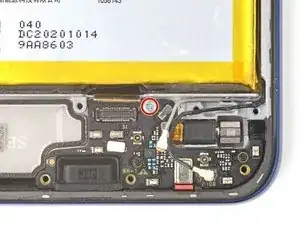
    • Use your Phillips screwdriver to remove the 2.5 mm-long screw securing the daughterboard.

  30. AgrgYZ1TKf1kdgts
    AgrgYZ1TKf1kdgts
    aUDPtnCODF3mHKqG
    RwrWyAYvPL2OMcEH
    • Move the black and gray antenna cables away from the daughterboard.

  31. L53vIcETVOgXm4hw
    L53vIcETVOgXm4hw
    BIIqgWuMoRwvQCKP
    hPCQauCsP5sGvBKc
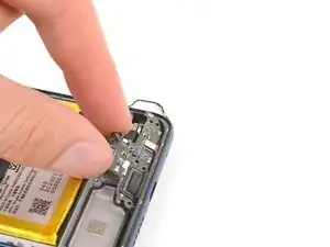
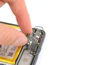
    • Grip the top edge of the daughterboard.

    • Lift and remove the daughterboard from its recess.

    • Be sure not to catch on any loose cables.

  32. llGDZV3rJtNNqLPJ
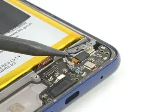
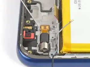
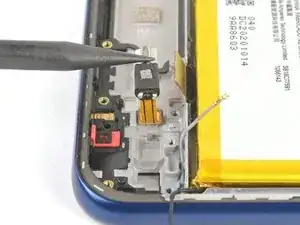
    • Apply highly-concentrated isopropyl alcohol (over 90%) to the vibration motor's flex cable.

    • Alternatively, use a heated iOpener, hair dryer, or heat gun to soften the adhesive.

    • Use caution to not overheat the battery or surrounding components.

  33. P13jyXJcUyevlCIv
    P13jyXJcUyevlCIv
    hoLEM1Ey1NXmWXQo
    X6rVUJKhBlOBUQaP
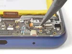
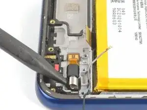
    • Insert the point of your spudger between the motor counterweight and the frame.

    • Pry the motor out of its recess and flip it over.

    • Don't fold the flex cable.

  34. XgXE1NHCyGhekIYQ
    XgXE1NHCyGhekIYQ
    Hgb4RMuroPMbhHBv
    4ybDrNfowJaLGDyZ
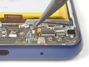
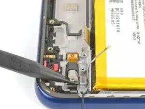
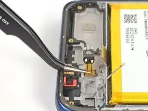
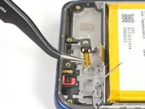
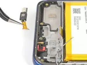
    • The vibration motor's flex cable is very fragile. Work slowly to prevent tearing the cable.

    • Use tweezers to grab and peel the base of the flex cable from the frame.

    • If the cable feels stuck or re-adheres, apply more isopropyl alcohol or heat.

    • Remove the vibration motor from the frame.

  35. tGgilysomuV6iAPJ
    tGgilysomuV6iAPJ
    XqUHQPQekMnTEVJW
    JffJIT2oVgM1ITl1
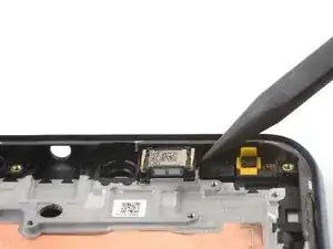
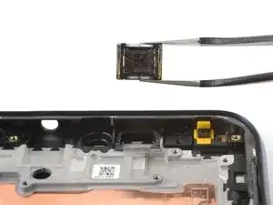
    • Insert the pointed end of your spudger between the right edge of the earpiece speaker and the motherboard.

    • Pry up on the speaker and remove it

    • During reassembly, ensure that the raised side of the connectors are toward the bottom of the device.

  36. p3PLJJZdI3Jd1Bru
    p3PLJJZdI3Jd1Bru
    SmGh4eKOZvYdIQLT
    efVZHgGQe1oXXfAi
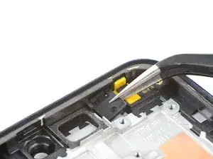
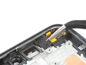
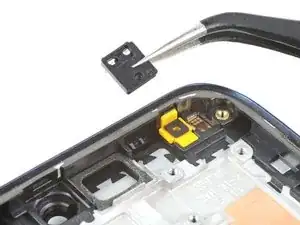
    • Use tweezers to grab and remove the proximity sensor bracket from its recess.

    • The rubber gasket is lightly adhered to the frame.

  37. xHUGjlWevVmdxV4m
    xHUGjlWevVmdxV4m
    3oGAtw63IcPjRIOe
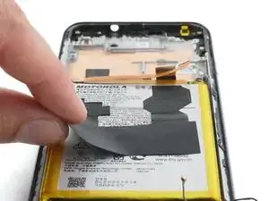
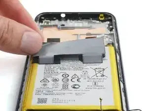
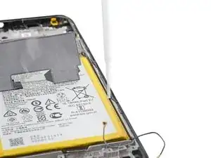
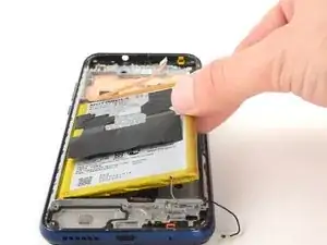
    • Fold the graphite heat dispersion film toward the top of the battery.

  38. iSOO6B5fyKiA4QeC
    • Heat an iOpener and apply it to the left edge of the screen for about two minutes.

    • A hair dryer, heat gun, or hot plate may also be used, but be careful not to overheat the phone—the display and internal battery are both susceptible to heat damage.

  39. Wlj5KWe3flKRY1xM
    • Additionally, you may use highly-concentrated isopropyl alcohol (over 90%) to further loosen the adhesive securing the battery.

    • Apply the isopropyl alcohol into the gaps between the sides of the battery and the frame.

  40. KC2EBgQcIPxNcIBB
    KC2EBgQcIPxNcIBB
    pObJxEdLDPcgkNH5
    1xuXId4bAtAZn6og
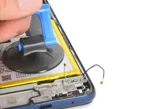
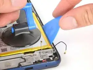
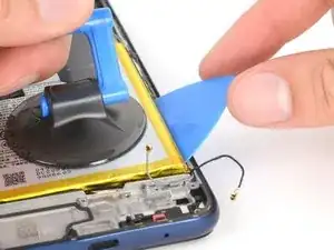
    • Place a suction handle on the center of the battery.

    • Insert an opening pick between the right edge of the battery and the frame.

    • Use a steady force to pull on the suction handle and simultaneously pry with the pick.

    • Don't use excessive force on the battery. Slow, consistent pressure is all that is required to free it from the frame.

    • Apply more heat or isopropyl alcohol if the battery readheres.

  41. ZnJYdNKT2BPskJ2o
    ZnJYdNKT2BPskJ2o
    pHwfViMH3y4ma3IF
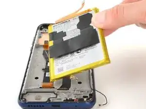
    • Remove the battery from its recess.

    • Don't reinstall a damaged or deformed battery, as doing so is a potential safety hazard.

    • Use this guide to install a battery with custom-cut adhesives, or use this guide to install a battery with an adhesive sheet.

  42. eWjkNBXNZsVtGJJs
    eWjkNBXNZsVtGJJs
    XIBFGSnZjXRwxJOF
    kPo6ybmkHELtRBTH
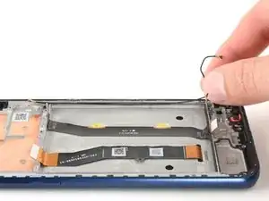
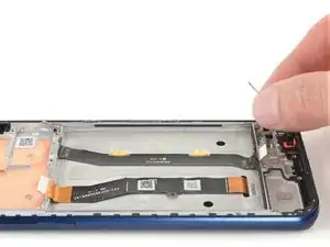
    • Grab and remove the black antenna cable from its recess in the frame.

    • During reassembly, leave 5 mm of slack on the upper ends of the antenna cables.

  43. 4aCiCU22dlXgHErT
    4aCiCU22dlXgHErT
    M4EVkXVAtD6XHSKt
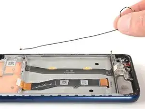
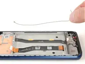
    • Grab and remove the gray antenna cable from its recess in the frame.

  44. FxGHErYBHLh1YAPp
    FxGHErYBHLh1YAPp
    16OW1xb6ykCqQ6l3
    pKjr36TZsESfpMmY
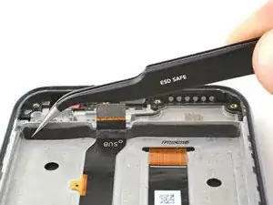
    • Use your tweezers to peel and remove the foam strip from the bottom of the battery recess.

  45. qNGOZsKtsOutWZmC
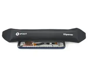
    • Heat an iOpener and apply it to the board cable for two minutes.

    • The iOpener may stick to the residue left over from the battery. Clean the surrounding surface with highly-concentrated isopropyl alcohol (over 90%) to prevent this.

    • A hair dryer, heat gun, or hot plate may also be used, but be careful not to overheat the phone—the display is susceptible to heat damage.

  46. QWYlxIpPCE1s6UcD
    QWYlxIpPCE1s6UcD
    J1cxmamVtym3cykT
    TR23r2lkdOWT4Hwl
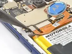
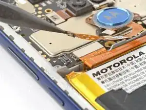
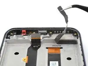
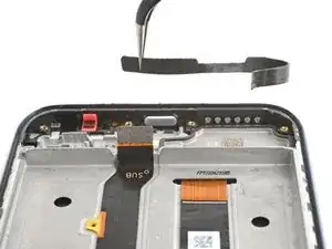
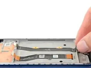
    • Grab the upper end of the board cable.

    • Peel and remove the cable from the frame.

  47. pDxyTUnmhgEur3UN
    • The screen is all that remains.

Abschluss

Compare your new replacement part to the original part—be sure to transfer remaining components and remove adhesive backings from the new part before installing.

To reassemble your device, follow these instructions in reverse order.

Take your e-waste to an R2 or e-Stewards certified recycler.

Repair didn’t go as planned? Try some basic troubleshooting, or ask our Answers community for help.

Clay Eickemeyer

Mitglied seit: 19/09/22

23447 Reputation

2 Kommentare

Excellent presentation. After looking at my broken phone for five months after it took a hundred mile trip stuck under the car hood being smashed over and over by the wiper arm, I decided to take the plunge.

Removing the battery was my biggest challenge, I was a bit concerned about getting the battery too hot, then got real concerned when I pried a little too hard because the glue wasn't softened enough, a little more heat gun and it cooperated.

Thanks for the concise instructions.

Larry Seppala -

please who can help in fix the motorola g 2021
Abdulsalam Hammed -