
Einleitung
Use this guide to replace the screen on your Nintendo Switch Lite. The screen consists of the LCD and digitizer. If you are only replacing the LCD, follow this guide. If you are only replacing the digitizer, follow this guide.
Note: Replacement adhesive is required to complete this guide.
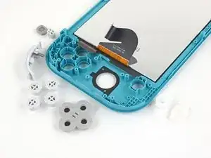
Note: Although removing the joysticks and buttons isn’t required, it makes this repair much easier.
-
-
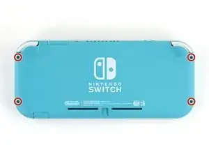
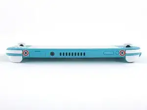
Use a JIS 000 driver or an official iFixit PH 000 driver to remove the following screws securing the back panel:
-
Two 3.6 mm-long screws on the top of the device
-
Two 3.6 mm-long screws on the bottom of the device
-
-
-
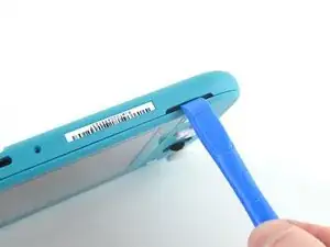
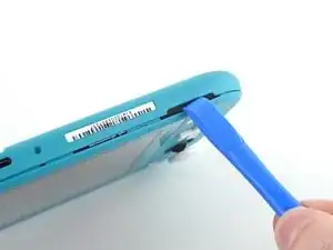
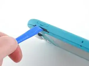
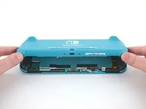
Insert an opening tool into the left speaker grille on the bottom of the device.
-
Twist the opening tool to release the clips securing the back panel.
-
-
-
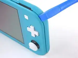
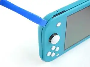
Slide the opening tool around the bottom-left corner to release the clips on the left side of the device.
-
-
-
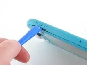
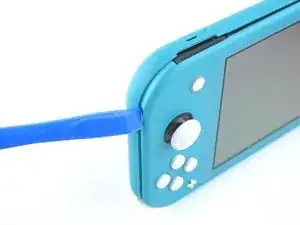
Insert an opening tool into the right speaker grille on the bottom of the device.
-
Twist the opening tool to release the clips.
-
-
-
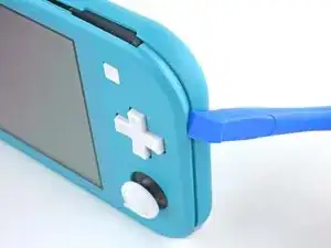
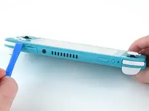
Slide and pry the opening tool around the bottom-right corner to release the clips on the right side of the device.
-
-
-
Continue sliding and prying the opening tool along the gap on the top of the device to release the clips.
-
-
-
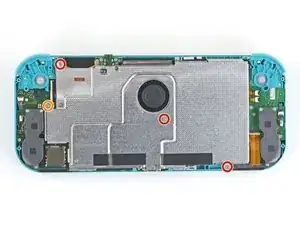
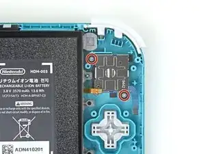
Use a JIS 000 driver or an official iFixit PH 000 driver to remove the following four screws:
-
Three 3.1 mm screws
-
One 4.5 mm screw
-
-
-
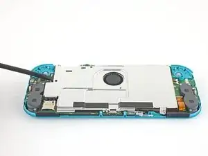
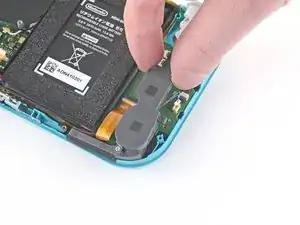
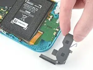
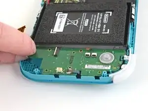
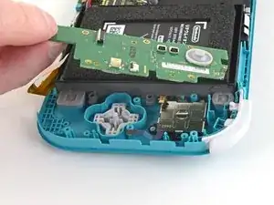
Use a spudger or your fingers to lift the shield plate up and out of the device.
-
Remove the shield plate.
-
-
-
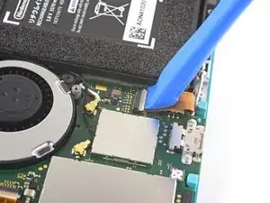
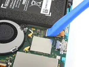
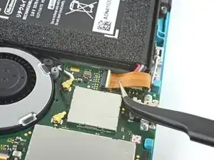
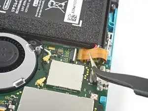
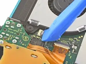
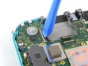
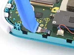
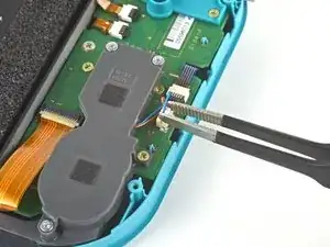
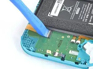
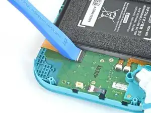
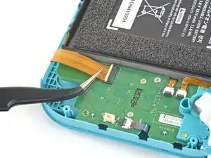
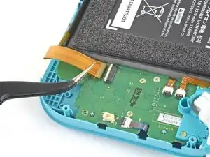
Use an opening tool or your fingernail to flip up the small, hinged locking flap on the motherboard interconnect cable's ZIF connector.
-
-
-
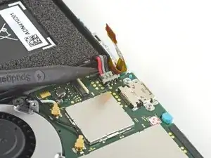
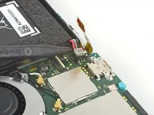
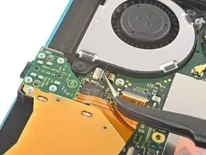
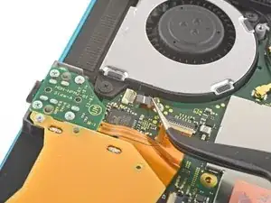
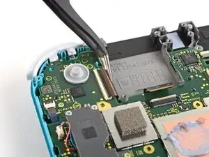
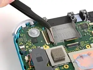
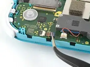
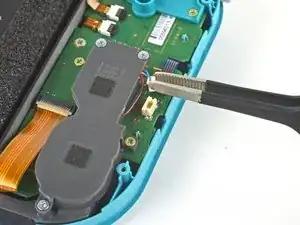
Use a pair of tweezers to slide the interconnect cable out of its connector on the motherboard.
-
-
-
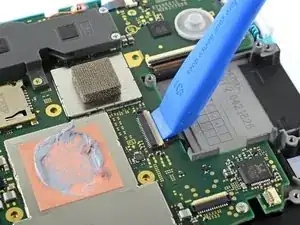
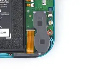
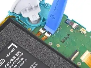
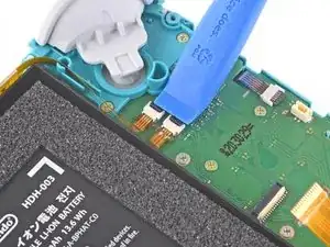
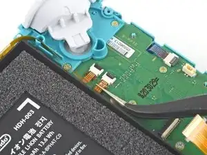
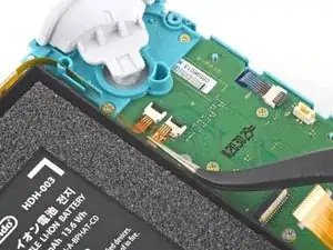
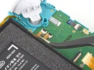
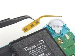
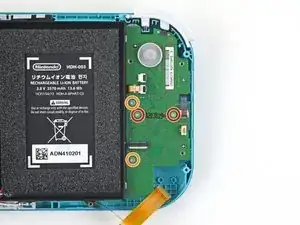
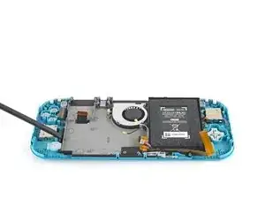
Use the point of a spudger to pry the battery connector straight up and out of its socket on the motherboard.
-
-
-
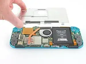
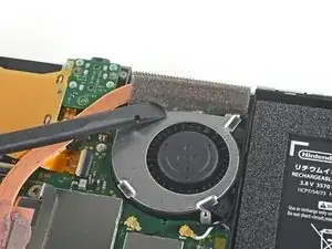
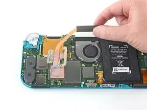
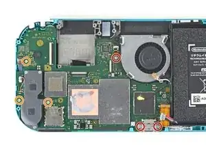
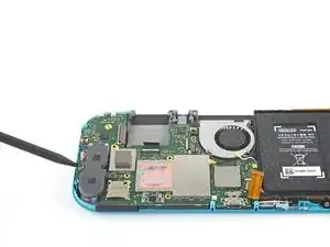
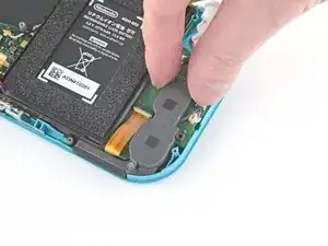
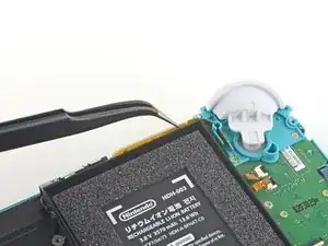
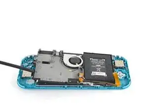
Use the flat end of a spudger or your fingers to carefully peel up the foam that's lightly adhered to the fan.
-
-
-
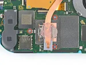
Use a JIS 000 driver or an official iFixit PH 000 driver to remove the three 3 mm screws securing the heat sink to the motherboard.
-
-
-
Use a spudger or your fingers to lift the heatsink up and off of the motherboard to remove it.
-
-
-
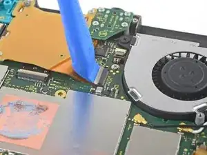
Use an opening tool or your fingernail to flip up the small, hinged locking flap on the game card reader cable's ZIF connector.
-
-
-
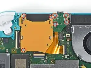
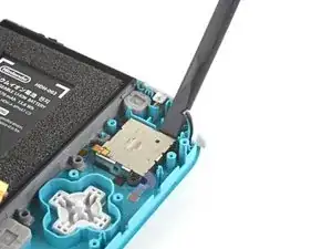
Use a JIS 000 driver or an official iFixit PH 000 driver to remove the seven 3.1 mm screws securing the game card reader and headphone jack.
-
-
-
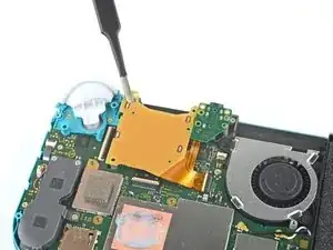
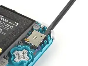
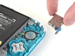
Use a pair of tweezers or your fingers to carefully lift the game card reader and maneuver it to the left to slide the cable out of its connector.
-
Remove the game card reader and headphone jack.
-
-
-
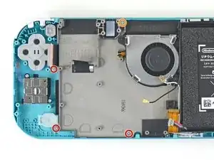
Use a JIS 000 driver or an official iFixit PH 000 driver to remove the two 4.5 mm screws securing the right trigger button assembly to the motherboard.
-
-
-
Use a pair of tweezers or your fingers to remove the right trigger button assembly's rubber pad if it didn't stay attached to the button assembly.
-
-
-
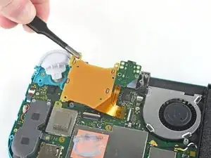
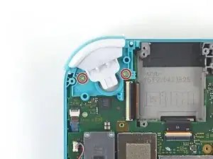
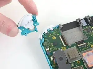
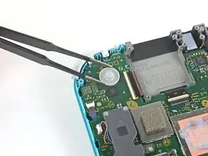
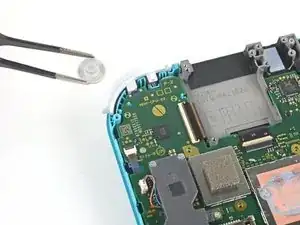
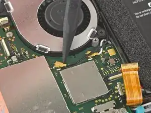
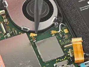
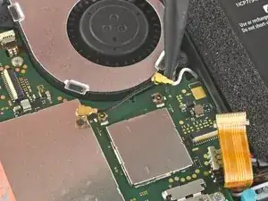
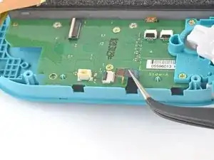
Use the point of a spudger to pry the black antenna cable straight up out of its socket on the motherboard.
-
Repeat the same process for the white antenna cable.
-
-
-
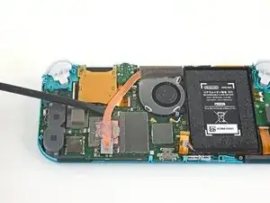
Use an opening tool or your fingernail to flip up the small, hinged locking flap on the fan cable's ZIF connector.
-
-
-
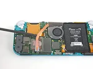
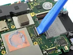
Use an opening tool or your fingernail to flip up the small, hinged locking flap on the screen cable's ZIF connector.
-
-
-
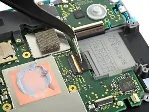
Use a pair of tweezers to slide the screen cable out of its connector on the motherboard.
-
-
-
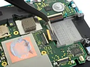
Use an opening tool or your fingernail to flip up the small, hinged locking flap on the digitizer cable's ZIF connector.
-
-
-
Use a pair of tweezers to slide the digitizer cable out of its connector on the motherboard.
-
-
-
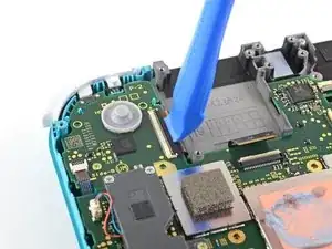
Use an opening tool or your fingernail to flip up the small, hinged locking flap on the right joystick cable's ZIF connector.
-
-
-
Use a pair of tweezers to slide the right joystick cable out of its connector on the motherboard.
-
-
-
Use a JIS 000 driver or an official iFixit PH 000 driver to remove the following six screws securing the motherboard:
-
Three 3.1 mm screws
-
Three 4.5 mm screws
-
-
-
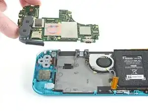
Insert a spudger in the gap between the frame and the motherboard and lift the motherboard up and out of its recess.
-
Remove the motherboard assembly.
-
-
-
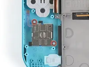
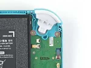
Use a JIS 000 driver or an official iFixit PH 000 driver to remove the two 3.5 mm screws securing the joystick.
-
-
-
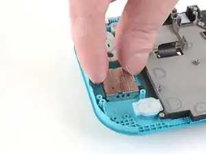
Use a pair of tweezers or your fingers to pull the left speaker cable straight up and out of its socket on the daughterboard.
-
-
-
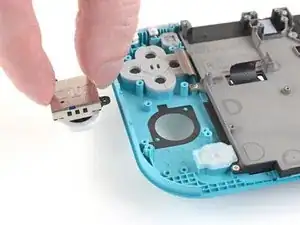
Use a JIS 000 driver or an official iFixit PH 000 driver to remove the 4.5 mm screw securing the left speaker module.
-
-
-
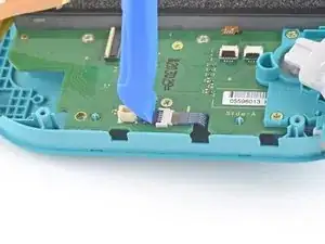
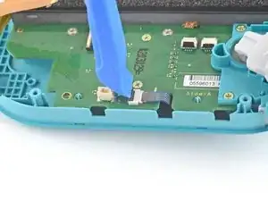
Use an opening tool or your fingernail to flip up the small, hinged locking flap on the motherboard interconnect cable's ZIF connector.
-
-
-
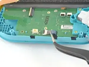
Use a pair of tweezers to slide the motherboard interconnect cable out of its connector on the daughterboard.
-
-
-
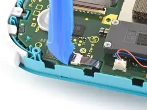
Use an opening tool or your fingernail to flip up the small, hinged locking flaps on the two ribbon cable ZIF connectors.
-
-
-
Use a pair of tweezers to slide the daughterboard screen cable out of its connector on the motherboard.
-
Repeat this procedure for the volume buttons cable.
-
-
-
Use an opening tool or your fingernail to flip up the small, hinged locking flap on the left joystick cable's ZIF connector.
-
-
-
Use a pair of tweezers to slide the left joystick cable out of its connector on the daughterboard.
-
-
-
Use a JIS 000 driver or an official iFixit PH 000 driver to remove the two 4.5 mm screws securing the left trigger button assembly.
-
-
-
Use a JIS 000 driver or an official iFixit PH 000 driver to remove the following four screws:
-
Two 4.5 mm screws
-
Two 6 mm screws
-
-
-
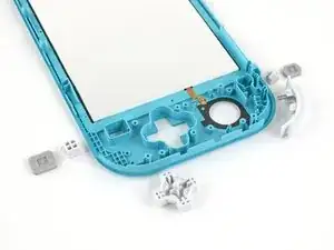
Use a JIS 000 driver or an official iFixit PH 000 driver to remove the two 3.5 mm screws securing the left joystick.
-
-
-
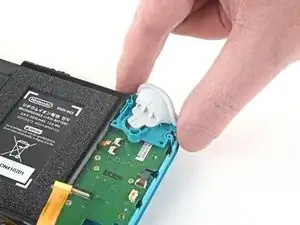
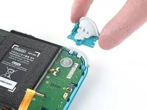
Use the flat end of a spudger to lift the joystick up and out of its recess.
-
Use your fingers to remove the joystick.
-
-
-
Use a JIS 000 driver or an official iFixit PH000 driver to remove the four screws securing the midframe assembly:
-
Three 2.5 mm screws
-
One 6 mm screw
-
-
-
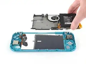
Use a spudger to pry the midframe assembly up until you can grip it with your fingers.
-
Grip the midframe assembly and pull up to remove it.
-
-
-
Flip the frame over so the screen is facing up.
-
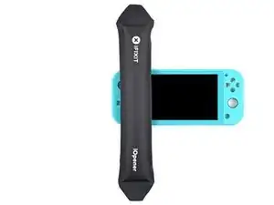
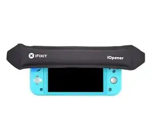
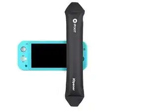
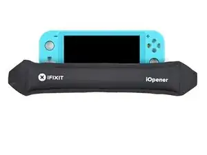
Heat an iOpener and apply it to the left edge of the screen for two minutes.
-
-
-
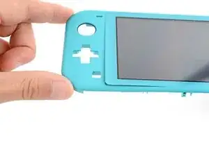
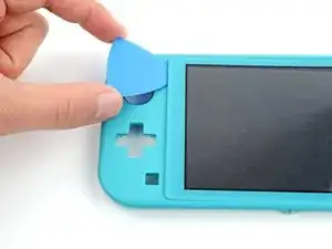
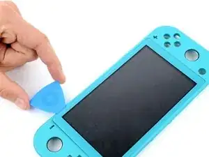
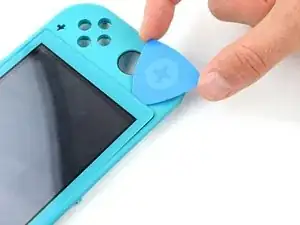
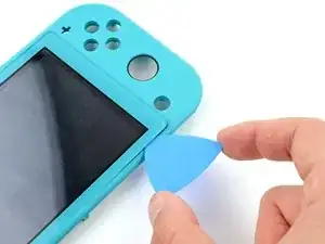
Lightly bend the left side of the frame away from the screen to create a gap in the bottom left corner.
-
Insert an opening pick in the gap.
-
-
-
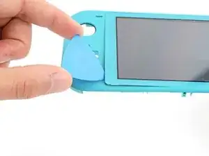
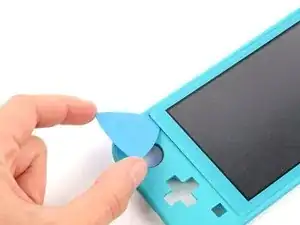
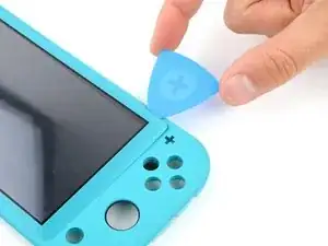
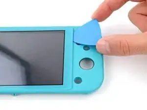
Slide the opening pick along the left edge.
-
Leave the pick inserted in the top left corner to prevent the adhesive from resealing.
-
-
-
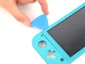
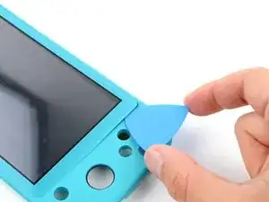
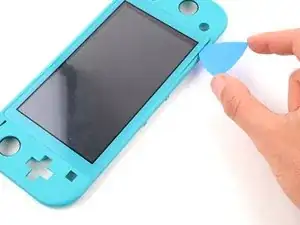
Slide the opening pick along the top edge.
-
Leave the opening pick inserted in the top right corner.
-
-
-
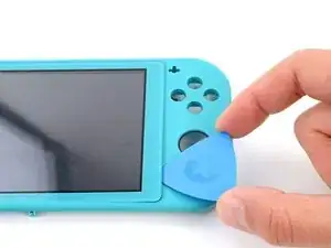
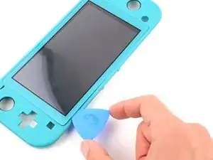
Slide the opening pick along the right edge.
-
Leave the opening pick inserted in the bottom right corner.
-
-
-
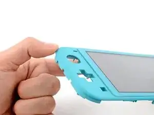
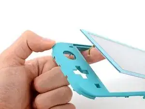
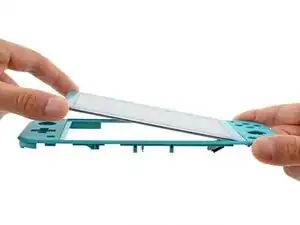
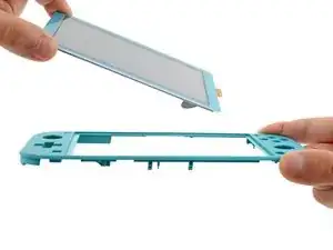
Grip the frame and push up on the underside of the screen's left edge to separate the adhesive securing it.
-


Compare your new replacement part to the original part—you may need to transfer remaining components or remove adhesive backings from the new part before you install it.
To reassemble your device, follow these instructions in reverse order.
Take your e-waste to an R2 or e-Stewards certified recycler.
Repair didn’t go as planned? Try some basic troubleshooting, or ask our Nintendo Switch Lite Answers community for help.

All my screws got stripped any ideas on how to remove?
Almost A Mammal -
A Y0 screwdriver seemed to work better for me.
Tommy Morrill -
What type of screw driver do I use to un screw the screws and which way
Luca Capito -